EP0327540B1 - Systeme de controle pour supports de donnees - Google Patents
Systeme de controle pour supports de donnees Download PDFInfo
- Publication number
- EP0327540B1 EP0327540B1 EP87906555A EP87906555A EP0327540B1 EP 0327540 B1 EP0327540 B1 EP 0327540B1 EP 87906555 A EP87906555 A EP 87906555A EP 87906555 A EP87906555 A EP 87906555A EP 0327540 B1 EP0327540 B1 EP 0327540B1
- Authority
- EP
- European Patent Office
- Prior art keywords
- data
- control
- control station
- transmitter
- data carrier
- Prior art date
- Legal status (The legal status is an assumption and is not a legal conclusion. Google has not performed a legal analysis and makes no representation as to the accuracy of the status listed.)
- Expired - Lifetime
Links
Images

Classifications
-
- G—PHYSICS
- G07—CHECKING-DEVICES
- G07F—COIN-FREED OR LIKE APPARATUS
- G07F7/00—Mechanisms actuated by objects other than coins to free or to actuate vending, hiring, coin or paper currency dispensing or refunding apparatus
- G07F7/08—Mechanisms actuated by objects other than coins to free or to actuate vending, hiring, coin or paper currency dispensing or refunding apparatus by coded identity card or credit card or other personal identification means
- G07F7/0866—Mechanisms actuated by objects other than coins to free or to actuate vending, hiring, coin or paper currency dispensing or refunding apparatus by coded identity card or credit card or other personal identification means by active credit-cards adapted therefor
-
- G—PHYSICS
- G06—COMPUTING; CALCULATING OR COUNTING
- G06K—GRAPHICAL DATA READING; PRESENTATION OF DATA; RECORD CARRIERS; HANDLING RECORD CARRIERS
- G06K19/00—Record carriers for use with machines and with at least a part designed to carry digital markings
- G06K19/06—Record carriers for use with machines and with at least a part designed to carry digital markings characterised by the kind of the digital marking, e.g. shape, nature, code
- G06K19/067—Record carriers with conductive marks, printed circuits or semiconductor circuit elements, e.g. credit or identity cards also with resonating or responding marks without active components
- G06K19/07—Record carriers with conductive marks, printed circuits or semiconductor circuit elements, e.g. credit or identity cards also with resonating or responding marks without active components with integrated circuit chips
- G06K19/077—Constructional details, e.g. mounting of circuits in the carrier
- G06K19/07701—Constructional details, e.g. mounting of circuits in the carrier the record carrier comprising an interface suitable for human interaction
- G06K19/07703—Constructional details, e.g. mounting of circuits in the carrier the record carrier comprising an interface suitable for human interaction the interface being visual
-
- G—PHYSICS
- G06—COMPUTING; CALCULATING OR COUNTING
- G06K—GRAPHICAL DATA READING; PRESENTATION OF DATA; RECORD CARRIERS; HANDLING RECORD CARRIERS
- G06K19/00—Record carriers for use with machines and with at least a part designed to carry digital markings
- G06K19/06—Record carriers for use with machines and with at least a part designed to carry digital markings characterised by the kind of the digital marking, e.g. shape, nature, code
- G06K19/067—Record carriers with conductive marks, printed circuits or semiconductor circuit elements, e.g. credit or identity cards also with resonating or responding marks without active components
- G06K19/07—Record carriers with conductive marks, printed circuits or semiconductor circuit elements, e.g. credit or identity cards also with resonating or responding marks without active components with integrated circuit chips
- G06K19/077—Constructional details, e.g. mounting of circuits in the carrier
- G06K19/07749—Constructional details, e.g. mounting of circuits in the carrier the record carrier being capable of non-contact communication, e.g. constructional details of the antenna of a non-contact smart card
- G06K19/07758—Constructional details, e.g. mounting of circuits in the carrier the record carrier being capable of non-contact communication, e.g. constructional details of the antenna of a non-contact smart card arrangements for adhering the record carrier to further objects or living beings, functioning as an identification tag
- G06K19/07762—Constructional details, e.g. mounting of circuits in the carrier the record carrier being capable of non-contact communication, e.g. constructional details of the antenna of a non-contact smart card arrangements for adhering the record carrier to further objects or living beings, functioning as an identification tag the adhering arrangement making the record carrier wearable, e.g. having the form of a ring, watch, glove or bracelet
-
- G—PHYSICS
- G06—COMPUTING; CALCULATING OR COUNTING
- G06K—GRAPHICAL DATA READING; PRESENTATION OF DATA; RECORD CARRIERS; HANDLING RECORD CARRIERS
- G06K7/00—Methods or arrangements for sensing record carriers, e.g. for reading patterns
- G06K7/0008—General problems related to the reading of electronic memory record carriers, independent of its reading method, e.g. power transfer
-
- G—PHYSICS
- G06—COMPUTING; CALCULATING OR COUNTING
- G06K—GRAPHICAL DATA READING; PRESENTATION OF DATA; RECORD CARRIERS; HANDLING RECORD CARRIERS
- G06K7/00—Methods or arrangements for sensing record carriers, e.g. for reading patterns
- G06K7/08—Methods or arrangements for sensing record carriers, e.g. for reading patterns by means detecting the change of an electrostatic or magnetic field, e.g. by detecting change of capacitance between electrodes
- G06K7/082—Methods or arrangements for sensing record carriers, e.g. for reading patterns by means detecting the change of an electrostatic or magnetic field, e.g. by detecting change of capacitance between electrodes using inductive or magnetic sensors
- G06K7/083—Methods or arrangements for sensing record carriers, e.g. for reading patterns by means detecting the change of an electrostatic or magnetic field, e.g. by detecting change of capacitance between electrodes using inductive or magnetic sensors inductive
- G06K7/084—Methods or arrangements for sensing record carriers, e.g. for reading patterns by means detecting the change of an electrostatic or magnetic field, e.g. by detecting change of capacitance between electrodes using inductive or magnetic sensors inductive sensing magnetic material by relative movement detecting flux changes without altering its magnetised state
-
- G—PHYSICS
- G06—COMPUTING; CALCULATING OR COUNTING
- G06K—GRAPHICAL DATA READING; PRESENTATION OF DATA; RECORD CARRIERS; HANDLING RECORD CARRIERS
- G06K7/00—Methods or arrangements for sensing record carriers, e.g. for reading patterns
- G06K7/10—Methods or arrangements for sensing record carriers, e.g. for reading patterns by electromagnetic radiation, e.g. optical sensing; by corpuscular radiation
- G06K7/10544—Methods or arrangements for sensing record carriers, e.g. for reading patterns by electromagnetic radiation, e.g. optical sensing; by corpuscular radiation by scanning of the records by radiation in the optical part of the electromagnetic spectrum
- G06K7/10821—Methods or arrangements for sensing record carriers, e.g. for reading patterns by electromagnetic radiation, e.g. optical sensing; by corpuscular radiation by scanning of the records by radiation in the optical part of the electromagnetic spectrum further details of bar or optical code scanning devices
- G06K7/1097—Optical sensing of electronic memory record carriers, such as interrogation of RFIDs with an additional optical interface
-
- G—PHYSICS
- G06—COMPUTING; CALCULATING OR COUNTING
- G06Q—INFORMATION AND COMMUNICATION TECHNOLOGY [ICT] SPECIALLY ADAPTED FOR ADMINISTRATIVE, COMMERCIAL, FINANCIAL, MANAGERIAL OR SUPERVISORY PURPOSES; SYSTEMS OR METHODS SPECIALLY ADAPTED FOR ADMINISTRATIVE, COMMERCIAL, FINANCIAL, MANAGERIAL OR SUPERVISORY PURPOSES, NOT OTHERWISE PROVIDED FOR
- G06Q20/00—Payment architectures, schemes or protocols
- G06Q20/30—Payment architectures, schemes or protocols characterised by the use of specific devices or networks
- G06Q20/36—Payment architectures, schemes or protocols characterised by the use of specific devices or networks using electronic wallets or electronic money safes
- G06Q20/363—Payment architectures, schemes or protocols characterised by the use of specific devices or networks using electronic wallets or electronic money safes with the personal data of a user
-
- G—PHYSICS
- G07—CHECKING-DEVICES
- G07B—TICKET-ISSUING APPARATUS; FARE-REGISTERING APPARATUS; FRANKING APPARATUS
- G07B15/00—Arrangements or apparatus for collecting fares, tolls or entrance fees at one or more control points
- G07B15/02—Arrangements or apparatus for collecting fares, tolls or entrance fees at one or more control points taking into account a variable factor such as distance or time, e.g. for passenger transport, parking systems or car rental systems
- G07B15/04—Arrangements or apparatus for collecting fares, tolls or entrance fees at one or more control points taking into account a variable factor such as distance or time, e.g. for passenger transport, parking systems or car rental systems comprising devices to free a barrier, turnstile, or the like
-
- G—PHYSICS
- G07—CHECKING-DEVICES
- G07C—TIME OR ATTENDANCE REGISTERS; REGISTERING OR INDICATING THE WORKING OF MACHINES; GENERATING RANDOM NUMBERS; VOTING OR LOTTERY APPARATUS; ARRANGEMENTS, SYSTEMS OR APPARATUS FOR CHECKING NOT PROVIDED FOR ELSEWHERE
- G07C9/00—Individual registration on entry or exit
- G07C9/10—Movable barriers with registering means
-
- G—PHYSICS
- G07—CHECKING-DEVICES
- G07C—TIME OR ATTENDANCE REGISTERS; REGISTERING OR INDICATING THE WORKING OF MACHINES; GENERATING RANDOM NUMBERS; VOTING OR LOTTERY APPARATUS; ARRANGEMENTS, SYSTEMS OR APPARATUS FOR CHECKING NOT PROVIDED FOR ELSEWHERE
- G07C9/00—Individual registration on entry or exit
- G07C9/20—Individual registration on entry or exit involving the use of a pass
- G07C9/28—Individual registration on entry or exit involving the use of a pass the pass enabling tracking or indicating presence
Definitions
- the invention relates to a control station for checking data in data carriers, in particular when checking an access authorization or the like, with a control device for reading passive data carriers to be inserted, on which the data are stored in magnetic or optical form, for example, the control result being at least a peripheral device, in particular forwarded to an access block.
- control stations are used for various purposes, for example on ski lifts, for checking or validating tickets, in parking garages to enable entry or exit etc.
- the insertion of passive data carriers, mainly magnetic cards, bar code cards, also punch cards etc., into the slot of a reader the control station requires a relatively large amount of time and causes user inconvenience in handling.
- Such a control station can be found, for example, in CA-A-1184658. It is used to check conventional admission cards with a tear-off control section, on which two different, machine-readable data codes are provided, one of which is visible and the other is attached invisibly or concealed to make counterfeiting more difficult.
- the admission tickets are inserted through a slot into the control station, which contains two data reading devices. The data read is compared, and if the visible and invisible data match, the admission ticket is considered valid, the control section is torn down, and the admission ticket is returned to the user.
- the valid admission ticket then turns a traffic light to green and opens a turnstile. Is due to mismatch if a forgery is detected, the red light of the traffic light flashes, an alarm sounds and the counterfeit card is ejected again.
- Active data carriers are also known, in particular for personal identification, the data carrier itself containing electronic components such as computers, displays, etc. Examples of this are shown in EP-B-19280 (identification card with electrical contact surfaces), EP-A-142013 (data carrier with inductive data transmission) and destruction of the data in the event of mechanical intervention), EP-A-168836 (data card for automated teller machines with optical data transmission) , EP-A-196028 (prepaid card with electrical contact surfaces) and WO-A-86/04705 (prepaid telephone card with inductive data transmission).
- US-A-4325146 shows a control system operating in a similar manner.
- a control station and approaching vehicles or the data carriers present in the vehicles made, for example at the entrance to the parking area.
- Authorized vehicles can thus pass a barrier that opens in time without stopping. The control is accelerated considerably.
- the active data carriers which are much more expensive than magnetic or punched cards, cannot easily be used in mass applications for low-value access, primarily because of the high costs involved. For example, for single tickets on ski lifts they are not accepted by the public. Existing control devices are inevitable there, although a check of active data carriers would significantly increase the performance of the control station.
- control devices for active data carriers provided on the vehicle are combined with conventional collection facilities in accordance with US-A-4338587 .
- Separate peripheral devices are provided for each type of control. While a positive control result of the active data carriers does not control peripheral devices, holding and warning devices are actuated in the event of a negative control result. With normal debt collection, however, a barrier is opened after the cash payment.
- the invention has now set itself the task of a control station of the type mentioned, in which a positive control result releases the blocked access or passage, for the control of passive and active data carriers, so that the waiting time is reduced and the comfort is increased for all users .
- control station has a second control device, which comprises a transceiver unit for distant communication with approximate active data carriers, in which a transceiver unit is also included, and that the two control devices have parallel outputs, the Output signals generated by means of the optionally used data carrier control the peripheral devices via a changeover switch.
- the user can select the type of data carrier and the data to be checked are stored in the respective data carriers in an initialization station.
- Active data carriers can be used repeatedly by deleting and entering new data. They can therefore be used, for example, as annual cards, permanent ID cards for repetitive events, etc., only the validity date having to be checked in the associated, second control facility of the control station, which is then re-stored when it is reused after expiry. If in the second control facility a continuous devaluation is carried out until a "supply" corresponding to the purchase price has been used up, the data carriers can also be used as multi-trip tickets, as entry tickets for events with consumption options (hospitality, entertainment and leisure facilities) etc.
- a residual value display can advantageously be made visible on a display, this residual value depending on the respective intended use, for example display of the expiry date, display after the penultimate trip of a multi-trip card or the like, in order to enable timely re-evaluation in an initialization station enable.
- a data carrier could also be issued with a deposit, or after its use be bought back again, and is also economical for mass use, since the production costs are only an acceptable percentage of the embodied value.
- the data carrier which can be read at a distance, only has to be brought into the control area of the transceiver unit of the second control device, where the authorization and / or the validity of the authorization is checked in a very short period of time, preferably under 1 second .
- the passive data carriers are still used, which are inserted into the associated first control device, read and if positive Control result to be thrown away.
- the common peripheral devices connected via the changeover switch for example a traffic light, a barrier, a turnstile, or a central computer for billing, etc., respond to any positive control result.
- both control devices are also arranged in a common housing.
- a particularly space-saving, externally encapsulated construction can also be realized in that one of the peripheral devices comprises a multi-colored traffic light arranged in the housing for displaying the control result, the transceiver unit of the second control device and the lamps of the traffic light from a common cover frosted glass are covered.
- the transceiver unit of the second control device is designed for radio transmission with a preferred carrier frequency range up to 250 kHz, so that only low transmission energy is required. This is particularly important for the energy supply of the active data carriers.
- a preferred embodiment provides that the carrier frequencies for the data transmission from the control station to the data carrier and from the data carrier to the control station are different, the transceiver unit of the control station being one Transmitting oscillator and the transceiver unit of the data carrier contains a frequency divider.
- the communication space of the second control device becomes significantly smaller than the object to be detected, so that data can only be transmitted within a limited environment of the second control device.
- the accidental presence of an active data carrier that cannot be addressed can be ruled out with certainty and a willful disturbance can at least be made considerably more difficult.
- conscious and intentional handling of the active data carrier is necessary, which is comparable in terms of the activity of the user to inserting a passive data carrier into a slot.
- the largest extent of the communication space perpendicular to the lane is provided, for example, with 10 cm to 30 cm, preferably 20 cm, and for a vehicle lane, this can be between 50 cm and 200 cm, preferably 100 cm.
- data transmission by means of light waves is provided, the infrared region in particular being selected here; however, laser light could also be used.
- the limited transmission range can also be shielded against external influences without any special effort when data is transmitted by means of light waves. This can be done by means of a delimitation diaphragm for the detection area which is provided at a distance from the transmitter and receiver.
- control device for reading the passive data carriers contains a read / write head and a print head following the insertion slot.
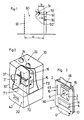
- a control station 70 (Fig. 1) is used for optional communication with active data carriers 50 and passive data carriers 50 'within a physical or even imaginary boundary 61 having detection space 60, the dimensions of which are provided with the data carrier 50, 50' object 51 (person or object) is coordinated.
- the detection space 60 can form a person passage lane with the size a, by which the boundary 61 is distanced from the control station 70.
- the control station 70 thus comprises two control devices 31, 32 which are accommodated in a common housing 30.
- the first control device 32 reads passive data carriers 50 ', in particular magnetic cards, punch cards, cards with bar codes etc., which are intended for one-time access, such as single trips or the like. They are inserted into the first control device 32 of the control station 70 in a conventional manner.
- passive data carrier 50 ' is only indicated by dashed lines in Fig. 1.
- the read data are fed to evaluation electronics 46.
- a print head 44 is also provided so that the control can be made visually visible. If data are also to be changed in a passive data carrier 50, a read / write head 43 (FIG. 7) is provided, with changes being made visible by the print head 44.
- the second control device 31 is provided for communication with active data carriers 50 which contain a microcomputer (FIGS. 5, 10), the data being transmitted to the second control device 31 by radio according to the first embodiment shown in FIGS. 2 to 5 .
- the transmit-receive frequencies are preferably in a range of 100 kHz and below.
- magnetic antennas can also be used for transmitter 15 and receiver 16, so that no undesired shielding effects occur.
- the low transmission energy limits the communication space to an environment 80 of the control station 70.
- the data carrier 50 Since the environment 80 has a maximum extension b, which is significantly smaller than the size a of the detection area, the data carrier 50 must be brought into the environment 80 of the control station 70 for the data transmission between the active data carrier 50 and the second control device. This means that the object 51 approaches the control station 70 to such an extent that a communication fault is accidentally or deliberately present in the detection area 60 other media is practically excluded. If the dimension a is 50 to 70 cm, for example, a suitable maximum extension b of the surrounding area 80 will be approximately 10 to 30 cm.
- the transmitting antennas 71, 48 and the receiving antenna 72, 49 are offset from one another by 90 ° both in the second control device 31 of the control station 70 (FIG. 2) and in the data carrier 50 (FIG. 3) , so that they do not influence each other magnetically. Due to the small extent b of the communication space, the formation of directionally independent antennas is generally unnecessary. However, it would be entirely conceivable to provide two receiving coils 72, 49 offset from one another in the control station 70 and / or in the data carrier 50. On the back, the housing 30 is provided with a shield 73.
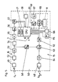
- the control station 70 sends out an identification number with a carrier frequency fo (eg 100 kHz).
- a carrier frequency fo eg 100 kHz
- the central unit 75 (CPU) of the control station transfers corresponding data into a shift register 76 (SR), from which these are read out serially in an encoder 77.
- the encoder 77 is connected to an oscillator 74 for the carrier frequency fo.
- the transmission antenna 71 is operated via corresponding amplifiers 78.
- the signals emitted by the control station 70 are received (FIG. 5) in the data carrier 50 by the receiving antenna 49 tuned to the carrier frequency fo.
- the signals are transmitted via a limiter 52 and an amplifier 53 a low-pass filter 54, which in turn is connected to a decoder 56.
- a timer 55 (t) is arranged between the low-pass filter 54 and the decoder 56, which prevents signals which are received accidentally from “waking up” the processor 20 (CPU) in the data carrier 50.
- the decoder 56 transfers the decoded data to a shift register 57 (SR), which wakes up the processor 20 via an interrupt, so that it can take over the read recognition received.
- SR shift register 57
- the processor 20 converts the read recognition using a defined algorithm and now in turn sends an additional data carrier number to the control station 70.
- the data carrier 50 requires the carrier frequency fo for the transmission traffic. This is via a frequency divider 58 (fo / fo 2nd ) fed to an encoder 63, which receives the corresponding data via a shift register 62 (SR) in front of processor 20.
- the transmission frequency is now fo / 2.
- This circuit has the advantage that no separate, constant oscillator is required in the data carrier 50, which oscillator must be matched to the control station 70.
- the signals pass through an amplifier 64 and transmitting antenna 48 of the data carrier 50 to the receiving antenna 72 of the second control device of the control station 70. From there they are fed to a decoder 83 via an amplifier 81 and a low-pass filter 82.
- the data arrive in the shift register 84 from the decoder to the central unit 75.
- the central unit 75 converts the received data using the same algorithm as the data carriers 50 and can thus identify any attempts at manipulation, with the transmission oscillator 74 being assigned a frequency divider 79.
- the same transmission frequency fo / 2 coming from the data carrier 50 can thus be compared directly.
- the respective real partner can interrupt the data transmission for a certain time or for a long time after a certain number of transmission attempts.
- control station 70 and the data carrier 50 are mutually recognized, the authenticity of both partners having been checked at the same time, so that the actual data traffic can take place, which is dependent on the specific application.
- control station 70 activates itself for the next application and calls again with its identifier until the next response is received from a subsequent data carrier 50.
- the processor 20 of the data carrier is normally in sleep mode, that is to say an inactive operating mode with minimal power consumption. It only takes action when valid data is received.
- a keyboard 66 for example for computing functions, for entering a personal identification number (PIN), etc. This enables certain actions to be made dependent on the input of the identification number.
- PIN personal identification number
- the data carrier 50 has its own switchover in order to enable minimal power consumption in inactive operation.
- This circuit consists of a clock oscillator 67, (fx), a programmable divider 68 (fn / fx) and a multiplexer 69 (MUX) for the LCD display 8. Program inaccuracies can be compensated for.
- the memory of processor 20 advantageously has a relatively small ROM area and a relatively large RAM area (e.g. 1 kb and 4 kb).
- the modules of the data carrier 50 described are advantageously integrated in a single chip, with the exception of the crystals, the LCD display 8 and the transmitter / receiver antennas 48, 49 and some peripheral components.
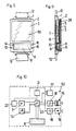
- FIG. 7 shows a second embodiment of a control station 70, the second control device 31 of which is provided for infrared data transmission. It contains a transmitting diode 27 and a receiving diode 47, an infrared filter 45, a control 35 and evaluation electronics 38, as well as the two-colored traffic light 33 with a red and a green lamp 34.
- the transmitting and receiving diodes 27, 47, the colored lamps 34 and a front optics 36 are accommodated in a receiving space 29, which is covered on the outside by a frosted glass pane 37.
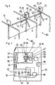
- 50 'of Similar signals emitted to the evaluation electronics 38, 46 are passed on to the traffic lights 33 and other connected peripheral devices such as a computer, a barrier, a turnstile 41, etc., via a changeover switch 39. 6 shows the latter in the example of a two-lane slide control station.
- 8 to 10 show an embodiment of an active data carrier for optical data transmission, in particular medium infrared waves.
- the electronics contained in the data carrier 50 can be seen in the block diagram from FIG. 10.
- the central microprocessor 20 (.mu.c) is connected to infrared transmission diodes as transmitter 15 with associated transmission logic 18, with an infrared reception diode as receiver 16 with associated reception logic 19 to which standby logic 17 is assigned, and to a current source 7, the current source 7, in particular if it is formed by a battery, is provided with a control logic 22.
- the data to be entered into the data carrier 50 are stored in a read-write memory 21, in particular an EEPROM or RAM, and can be made visible on a liquid crystal display 8 by pressing a button 13.
- the current source 7 can also be a rechargeable battery or a solar cell.
- Each active data carrier 50 has a housing which consists of a lower part 1 and an upper part 2 (FIGS. 3, 8, 9).
- the housing is in particular made of plastic, wherein the two parts 1, 2 are preferably welded together.
- the lower part 1 of the housing can be in various embodiments. As shown, receptacles for a bracelet 12 are provided on the lower part 1, so that an active data carrier 50, similar to a watch, can be worn on the forearm or wrist (object 51, FIG. 1).
- the lower part 1 can also be provided with a clip be and carry an additional labeling field.
- the housing can also be designed as a key fob, a cord attached to a key ring being wound on a spring roller in the lower part.
- the lower part 1 can also be provided with a self-adhesive layer. The latter two versions are primarily intended for vehicles (parking garages, toll stations, etc.).
- the upper part 2 has a socket 28 for a photo 5 or the like, which is closed by a cover 3.
- the cover 3 carries on the inside an adhesive coating 4 to which the photo 5 is glued.
- the type of adhesive is chosen so that when the photo 5 is detached, it is destroyed, and thus the exchange for another photo becomes visible.
- Under the cover 3, a cover 11 is inserted into the upper part 2, under which the liquid crystal display 8 is arranged.
- the transmitter 15 and the receiver 16 are provided for receiving and delivering the data.
- the key 13 serves to visualize the data contained in the data carrier 50 on the display 8.
- On the display 8 there is also a number field 14 with a visually readable, individual number, which can be stamped or printed, for example.
- the same "serial number" can also be provided on cover 3 or on photo 5.
- the display 8 is fed in the usual way at the push of a button via contacts 10 by a chip 9 which is arranged on a substrate.
- the power supply comes from a power source 7, for example a battery, a solar cell, etc.
- the data carrier forms a multi-trip card or point card, not only is the validity checked in the control station 70, but a partial validation is carried out.
- the additional storage of its individual number is of particular advantage, since the second control device of the control station can also be used to keep records of the continuous cancellation, if this is connected to a computer, and the respective data to a number journal be transmitted. Since the active data carrier 50 contains a microcomputer, information and functions can be freely divided between the data carrier 50 and the control station 70, which complement one another or possibly also overlap.
Landscapes
- Physics & Mathematics (AREA)
- Engineering & Computer Science (AREA)
- General Physics & Mathematics (AREA)
- Theoretical Computer Science (AREA)
- Business, Economics & Management (AREA)
- Artificial Intelligence (AREA)
- Computer Vision & Pattern Recognition (AREA)
- Accounting & Taxation (AREA)
- Computer Hardware Design (AREA)
- Microelectronics & Electronic Packaging (AREA)
- Electromagnetism (AREA)
- Finance (AREA)
- Computer Networks & Wireless Communication (AREA)
- Strategic Management (AREA)
- General Business, Economics & Management (AREA)
- General Health & Medical Sciences (AREA)
- Health & Medical Sciences (AREA)
- Toxicology (AREA)
- Devices For Checking Fares Or Tickets At Control Points (AREA)
- Selective Calling Equipment (AREA)
- Mobile Radio Communication Systems (AREA)
- Optical Communication System (AREA)
- Cash Registers Or Receiving Machines (AREA)
- Communication Control (AREA)
- Exchange Systems With Centralized Control (AREA)
- Near-Field Transmission Systems (AREA)
- Error Detection And Correction (AREA)
Claims (7)
Applications Claiming Priority (6)
| Application Number | Priority Date | Filing Date | Title |
|---|---|---|---|
| AT2820/86 | 1986-10-23 | ||
| AT0282086A AT391375B (de) | 1986-10-23 | 1986-10-23 | Datentraeger zum datenverkehr mit mindestens einer kontrollstation |
| AT0281986A AT391374B (de) | 1986-10-23 | 1986-10-23 | Kontrollstation zur ueberpruefung von daten in datentraegern |
| AT0281886A AT391373B (de) | 1986-10-23 | 1986-10-23 | Initialisierungsstation zur erstmaligen eingabe von personen zuordnenden daten in datentraeger |
| AT2818/86 | 1986-10-23 | ||
| AT2819/86 | 1986-10-23 |
Publications (2)
| Publication Number | Publication Date |
|---|---|
| EP0327540A1 EP0327540A1 (fr) | 1989-08-16 |
| EP0327540B1 true EP0327540B1 (fr) | 1991-09-25 |
Family
ID=27148942
Family Applications (2)
| Application Number | Title | Priority Date | Filing Date |
|---|---|---|---|
| EP87906555A Expired - Lifetime EP0327540B1 (fr) | 1986-10-23 | 1987-10-16 | Systeme de controle pour supports de donnees |
| EP87906556A Expired - Lifetime EP0327541B1 (fr) | 1986-10-23 | 1987-10-16 | Systeme de communication automatisee pour la transmission de donnees |
Family Applications After (1)
| Application Number | Title | Priority Date | Filing Date |
|---|---|---|---|
| EP87906556A Expired - Lifetime EP0327541B1 (fr) | 1986-10-23 | 1987-10-16 | Systeme de communication automatisee pour la transmission de donnees |
Country Status (6)
| Country | Link |
|---|---|
| US (1) | US5124535A (fr) |
| EP (2) | EP0327540B1 (fr) |
| JP (2) | JPH02500469A (fr) |
| AT (2) | ATE67874T1 (fr) |
| DE (2) | DE3773392D1 (fr) |
| WO (2) | WO1988003296A1 (fr) |
Cited By (1)
| Publication number | Priority date | Publication date | Assignee | Title |
|---|---|---|---|---|
| DE19541634B4 (de) * | 1994-11-15 | 2004-10-28 | Mitsubishi Denki K.K. | Zugangskontrollvorrichtung zum Verarbeiten einer den Zugang passierenden berührungslosen Chipkarte |
Families Citing this family (51)
| Publication number | Priority date | Publication date | Assignee | Title |
|---|---|---|---|---|
| ATE67874T1 (de) * | 1986-10-23 | 1991-10-15 | Skidata Gmbh | Kontrolleinrichtung fuer datentraeger. |
| IT1211771B (it) * | 1987-09-11 | 1989-11-03 | Rinaldi Massimo | Sistema di controllo di traffico per mezzi mobili e/o persone utilizzante una stazione fissa ed un elemento programmabile portato da detti mezzi mobili e/o persone |
| FR2627610B1 (fr) * | 1988-02-22 | 1991-04-05 | Cga Hbs | Systeme de peage pour utilisateurs de moyens de transport |
| FR2636154B1 (fr) * | 1988-09-08 | 1991-04-19 | Regie Autonome Transports | Procede de peage a infrarouge sans contact par carte a memoire, notamment pour moyen de transport, et dispositif de peage utilisant un tel procede |
| FR2642870A2 (fr) * | 1988-12-16 | 1990-08-10 | Daibilian Stephan | Dispositif enregistreur et indicateur de messages |
| FR2640782A1 (fr) * | 1988-12-16 | 1990-06-22 | Daibilian Stephan | Dispositif enregistreur et indicateur de messages |
| FR2642202B1 (fr) * | 1989-01-25 | 1994-02-18 | Urba 2000 | Systeme de paiement electronique de transports et de services publics par cartes a microcircuit |
| US5237164A (en) * | 1989-05-12 | 1993-08-17 | Sony Corporation | Card having retroreflective bar codes and a magnetic stripe |
| NL8902818A (nl) * | 1989-11-15 | 1991-06-03 | Nedap Nv | Geautomatiseerd afrekensysteem. |
| JP2617012B2 (ja) * | 1990-03-02 | 1997-06-04 | ダイコク電機株式会社 | レジャー施設の管理システム |
| JP3003043B2 (ja) * | 1990-04-18 | 2000-01-24 | 横河電機株式会社 | 携帯可能記憶媒体装置 |
| EP0496344B1 (fr) * | 1991-01-22 | 1998-04-01 | SkiData AG | Dispositif pour l'autorisation de l'utilisation d'un appareil avec une unité d'actionnement |
| JPH05122137A (ja) * | 1991-10-30 | 1993-05-18 | Aiphone Co Ltd | 位置情報送出機能付移動無線システム |
| JP3599336B2 (ja) * | 1992-02-18 | 2004-12-08 | シチズン時計株式会社 | データキャリヤシステム、及び固定施設におけるアンテナ |
| ATE147177T1 (de) * | 1992-10-22 | 1997-01-15 | Skidata Gmbh | Datenträger |
| JP2744741B2 (ja) * | 1992-10-27 | 1998-04-28 | 三菱電機株式会社 | データ処理装置およびそのカード挿入部 |
| WO1994015316A2 (fr) * | 1992-12-18 | 1994-07-07 | Skidata Computer Gesellschaft M.B.H. | Support de donnees |
| DE9302481U1 (fr) * | 1993-02-20 | 1993-04-08 | Parkautomatik Hans Farmont Gmbh, 4000 Duesseldorf, De | |
| FR2702065B1 (fr) * | 1993-02-24 | 1996-10-25 | Angewandte Digital Elektronik | Appareil à cartes réalisant une télétransmission décelable. |
| DE4308193C2 (de) * | 1993-03-15 | 1998-05-14 | Siemens Ag | Benutzungskontrollanlage für Lifte und Seilbahnen |
| AT400775B (de) * | 1993-05-03 | 1996-03-25 | Skidata Gmbh | Vereinzelungseinrichtung an einem durchgang |
| DE4326029C2 (de) * | 1993-08-03 | 1995-05-24 | Amphenol Tuchel Elect | Leser für Informationskarten |
| SE9304087D0 (sv) * | 1993-12-08 | 1993-12-08 | Kalix Eliktronik Ab | Biljett |
| GB9608173D0 (en) * | 1996-04-19 | 1996-06-26 | Hunter Geoffrey S R | Electrically controlled access/monitoring system |
| FR2754084B1 (fr) * | 1996-09-30 | 1998-12-18 | Fontaine Sa | Lecteur electronique de cartes pour la commande d'une serrure |
| DE29823424U1 (de) * | 1997-11-17 | 1999-06-24 | Allweiler Ag | Kreiselpumpe mit Gleitringdichtung |
| IT1306105B1 (it) * | 1998-01-21 | 2001-05-29 | P & S S R L | Metodo ed apparecchiatura per la convalida di documenti di viaggio |
| US6617960B1 (en) | 1998-02-18 | 2003-09-09 | Teamaxess Ticketing Gmbh | Arrangement for controlling access of persons, and access terminal |
| EP1135751A1 (fr) * | 1998-11-30 | 2001-09-26 | Joachim Albrecht | Procede de decompte du prix d'un billet lors de l'utilisation des transports publics |
| US6145742A (en) * | 1999-09-03 | 2000-11-14 | Drexler Technology Corporation | Method and system for laser writing microscopic data spots on cards and labels readable with a CCD array |
| US9697650B2 (en) * | 2000-06-09 | 2017-07-04 | Flash Seats, Llc | Method and system for access verification within a venue |
| US20060095344A1 (en) * | 2000-06-09 | 2006-05-04 | Nakfoor Brett A | System and method for fan lifecycle management |
| US8346580B2 (en) * | 2000-06-09 | 2013-01-01 | Flash Seats, Llc | System and method for managing transfer of ownership rights to access to a venue and allowing access to the venue to patron with the ownership right |
| US6496809B1 (en) * | 2000-06-09 | 2002-12-17 | Brett Nakfoor | Electronic ticketing system and method |
| US6629019B2 (en) * | 2000-09-18 | 2003-09-30 | Amusement Soft, Llc | Activity management system |
| DE10046335A1 (de) * | 2000-09-19 | 2002-04-18 | Skidata Ag | Zugangskontrolleinrichtung |
| US9740988B1 (en) | 2002-12-09 | 2017-08-22 | Live Nation Entertainment, Inc. | System and method for using unique device indentifiers to enhance security |
| US9477820B2 (en) | 2003-12-09 | 2016-10-25 | Live Nation Entertainment, Inc. | Systems and methods for using unique device identifiers to enhance security |
| US10366373B1 (en) | 2002-12-09 | 2019-07-30 | Live Nation Entertainment, Incorporated | Apparatus for access control and processing |
| JP3951298B2 (ja) | 2002-12-17 | 2007-08-01 | ソニー株式会社 | 通信装置および通信方法 |
| US8078483B1 (en) | 2003-12-16 | 2011-12-13 | Ticketmaster | Systems and methods for queuing access to network resources |
| US9608929B2 (en) | 2005-03-22 | 2017-03-28 | Live Nation Entertainment, Inc. | System and method for dynamic queue management using queue protocols |
| EP1987441B1 (fr) | 2006-02-07 | 2017-10-04 | Ticketmaster | Procédés et systèmes utilisés pour réduire une utilisation par rafales d'un système informatique en réseau |
| US8763902B2 (en) | 2006-12-07 | 2014-07-01 | Smart Systems Innovations, Llc | Mass transit fare processing system |
| US8281990B2 (en) | 2006-12-07 | 2012-10-09 | Smart Systems Innovations, Llc | Public transit system fare processor for transfers |
| US9807096B2 (en) | 2014-12-18 | 2017-10-31 | Live Nation Entertainment, Inc. | Controlled token distribution to protect against malicious data and resource access |
| SK288641B6 (sk) | 2008-10-15 | 2019-02-04 | Smk Corporation | Spôsob komunikácie s POS terminálom, frekvenčný konventor k POS terminálu |
| FR2950450B1 (fr) * | 2009-09-18 | 2013-10-11 | Oberthur Technologies | Procede de verification de la validite d'un ticket electronique de stationnement. |
| US9781170B2 (en) | 2010-06-15 | 2017-10-03 | Live Nation Entertainment, Inc. | Establishing communication links using routing protocols |
| US10096161B2 (en) | 2010-06-15 | 2018-10-09 | Live Nation Entertainment, Inc. | Generating augmented reality images using sensor and location data |
| AU2011268420B2 (en) | 2010-06-15 | 2014-05-01 | Ticketmaster, Llc | Methods and systems for computer aided event and venue setup and modeling and interactive maps |
Family Cites Families (16)
| Publication number | Priority date | Publication date | Assignee | Title |
|---|---|---|---|---|
| CA1004362A (en) * | 1972-04-11 | 1977-01-25 | Gretag Aktiengesellschaft | System for the individual identification of a plurality of individuals |
| US3866874A (en) * | 1973-03-26 | 1975-02-18 | Scott & Fetzer Co | Bracket for mounting awnings and the like |
| US4338587A (en) * | 1979-02-23 | 1982-07-06 | Chiappetti Arthur B | Toll collection system |
| US4325146A (en) * | 1979-12-20 | 1982-04-13 | Lennington John W | Non-synchronous object identification system |
| SU1068051A3 (ru) * | 1980-05-19 | 1984-01-15 | Таг Радионикс Лимитед (Фирма) | Устройство дл передачи и приема сигналов |
| US4476468A (en) * | 1981-06-22 | 1984-10-09 | Light Signatures, Inc. | Secure transaction card and verification system |
| GB2092353B (en) * | 1981-01-30 | 1984-05-31 | Halpern John Wolfgang | Token |
| FR2501396B1 (fr) * | 1981-03-05 | 1985-10-11 | Dassault Electronique | Systeme de controle d'acces, notamment pour le passage de points de peage |
| GB8332995D0 (en) * | 1983-12-09 | 1984-01-18 | Hickie C J | Identity device |
| CA1184658A (fr) * | 1984-01-06 | 1985-03-26 | Mercury Graphics Corporation | Billet anti-contrefacon et systeme connexe |
| JPS6125288A (ja) * | 1984-07-13 | 1986-02-04 | 神鋼電機株式会社 | 自動集改札装置 |
| GB2164825B (en) * | 1984-09-19 | 1988-05-11 | Satellite Video Systems Ltd | Coded transponder for indentification system |
| JPS61174256A (ja) * | 1985-01-30 | 1986-08-05 | Nippon Shokubai Kagaku Kogyo Co Ltd | 紫外線硬化型樹脂組成物 |
| GB8509135D0 (en) * | 1985-04-10 | 1985-05-15 | Gen Electric Co Plc | Transaction system |
| GB2193021B (en) * | 1986-07-24 | 1990-07-25 | Stanley Electric Co Ltd | Optical identification card system |
| ATE67874T1 (de) * | 1986-10-23 | 1991-10-15 | Skidata Gmbh | Kontrolleinrichtung fuer datentraeger. |
-
1987
- 1987-10-16 AT AT87906555T patent/ATE67874T1/de active
- 1987-10-16 EP EP87906555A patent/EP0327540B1/fr not_active Expired - Lifetime
- 1987-10-16 WO PCT/AT1987/000060 patent/WO1988003296A1/fr active IP Right Grant
- 1987-10-16 DE DE8787906556T patent/DE3773392D1/de not_active Expired - Lifetime
- 1987-10-16 DE DE8787906555T patent/DE3773391D1/de not_active Expired - Lifetime
- 1987-10-16 EP EP87906556A patent/EP0327541B1/fr not_active Expired - Lifetime
- 1987-10-16 JP JP62505994A patent/JPH02500469A/ja active Pending
- 1987-10-16 JP JP62505995A patent/JPH02500470A/ja active Pending
- 1987-10-16 US US07/358,376 patent/US5124535A/en not_active Expired - Lifetime
- 1987-10-16 AT AT87906556T patent/ATE67875T1/de not_active IP Right Cessation
- 1987-10-16 WO PCT/AT1987/000059 patent/WO1988003295A1/fr active IP Right Grant
Cited By (1)
| Publication number | Priority date | Publication date | Assignee | Title |
|---|---|---|---|---|
| DE19541634B4 (de) * | 1994-11-15 | 2004-10-28 | Mitsubishi Denki K.K. | Zugangskontrollvorrichtung zum Verarbeiten einer den Zugang passierenden berührungslosen Chipkarte |
Also Published As
| Publication number | Publication date |
|---|---|
| EP0327541B1 (fr) | 1991-09-25 |
| WO1988003296A1 (fr) | 1988-05-05 |
| JPH02500470A (ja) | 1990-02-15 |
| DE3773391D1 (de) | 1991-10-31 |
| ATE67875T1 (de) | 1991-10-15 |
| ATE67874T1 (de) | 1991-10-15 |
| JPH02500469A (ja) | 1990-02-15 |
| EP0327541A1 (fr) | 1989-08-16 |
| EP0327540A1 (fr) | 1989-08-16 |
| DE3773392D1 (de) | 1991-10-31 |
| US5124535A (en) | 1992-06-23 |
| WO1988003295A1 (fr) | 1988-05-05 |
Similar Documents
| Publication | Publication Date | Title |
|---|---|---|
| EP0327540B1 (fr) | Systeme de controle pour supports de donnees | |
| DE4292340B4 (de) | Ein elektronischer Pass | |
| DE2852941C2 (de) | In der Hand tragbare Datenstation | |
| DE69334088T2 (de) | System zum Identifizieren beweglicher Objekte | |
| DE60033235T2 (de) | Informations-ein-/ausgabe-einheit | |
| EP0340222A1 (fr) | Dispositif manuel portatif de traitement automatique de donnees enregistrees sur des supports de donnees. | |
| DE3412663A1 (de) | Chipkartensystem | |
| AT501366B1 (de) | Uhr, insbesondere armbanduhr | |
| DE3830643A1 (de) | Verkehrssteuersystem fuer sich bewegende einrichtungen und/oder menschen | |
| EP0617818B1 (fr) | Support de donnees | |
| US5202550A (en) | Device for machine communication in data transmission | |
| EP0035692A1 (fr) | Dispositif pour produire le signal de réponse d'une installation destinée à l'identification automatique d'objets et/ou d'êtres vivants | |
| EP1514248A1 (fr) | Systeme et procede d'analyse de presence d'objets | |
| DE3929879A1 (de) | Parkkarte fuer notrufgesicherte parkhaeuser oder parkgelaende | |
| WO1993023826A1 (fr) | Support d'information se presentant sous forme de carte et son utilisation | |
| DE19929925A1 (de) | Tragbare Uhr | |
| DE3222349A1 (de) | Elektronische uhr | |
| AT391375B (de) | Datentraeger zum datenverkehr mit mindestens einer kontrollstation | |
| DE4311385C2 (de) | Identifikationskarte | |
| EP0813171B1 (fr) | Interface utilisateur mobile | |
| AT391374B (de) | Kontrollstation zur ueberpruefung von daten in datentraegern | |
| DE69737390T2 (de) | Tragbares Objekt, insbesondere Uhr mit mehreren auswählbaren elektronischen Modulen | |
| AT391373B (de) | Initialisierungsstation zur erstmaligen eingabe von personen zuordnenden daten in datentraeger | |
| AT401584B (de) | Datenträger | |
| EP1157362A1 (fr) | Procede d'enregistrement d'une autorisation d'acces |
Legal Events
| Date | Code | Title | Description |
|---|---|---|---|
| PUAI | Public reference made under article 153(3) epc to a published international application that has entered the european phase |
Free format text: ORIGINAL CODE: 0009012 |
|
| 17P | Request for examination filed |
Effective date: 19890303 |
|
| AK | Designated contracting states |
Kind code of ref document: A1 Designated state(s): AT BE CH DE FR GB IT LI LU NL SE |
|
| RAP1 | Party data changed (applicant data changed or rights of an application transferred) |
Owner name: SKIDATA COMPUTER GESELLSCHAFT M.B.H. |
|
| 17Q | First examination report despatched |
Effective date: 19910228 |
|
| GRAA | (expected) grant |
Free format text: ORIGINAL CODE: 0009210 |
|
| AK | Designated contracting states |
Kind code of ref document: B1 Designated state(s): AT BE CH DE FR GB IT LI LU NL SE |
|
| PG25 | Lapsed in a contracting state [announced via postgrant information from national office to epo] |
Ref country code: BE Effective date: 19910925 |
|
| REF | Corresponds to: |
Ref document number: 67874 Country of ref document: AT Date of ref document: 19911015 Kind code of ref document: T |
|
| ITF | It: translation for a ep patent filed |
Owner name: JACOBACCI & PERANI S.P.A. |
|
| PG25 | Lapsed in a contracting state [announced via postgrant information from national office to epo] |
Ref country code: LU Free format text: LAPSE BECAUSE OF NON-PAYMENT OF DUE FEES Effective date: 19911031 |
|
| REF | Corresponds to: |
Ref document number: 3773391 Country of ref document: DE Date of ref document: 19911031 |
|
| GBT | Gb: translation of ep patent filed (gb section 77(6)(a)/1977) | ||
| ET | Fr: translation filed | ||
| PLBE | No opposition filed within time limit |
Free format text: ORIGINAL CODE: 0009261 |
|
| STAA | Information on the status of an ep patent application or granted ep patent |
Free format text: STATUS: NO OPPOSITION FILED WITHIN TIME LIMIT |
|
| 26N | No opposition filed | ||
| PGFP | Annual fee paid to national office [announced via postgrant information from national office to epo] |
Ref country code: NL Payment date: 19941031 Year of fee payment: 8 |
|
| EAL | Se: european patent in force in sweden |
Ref document number: 87906555.5 |
|
| PG25 | Lapsed in a contracting state [announced via postgrant information from national office to epo] |
Ref country code: NL Effective date: 19950727 |
|
| PGFP | Annual fee paid to national office [announced via postgrant information from national office to epo] |
Ref country code: GB Payment date: 19951013 Year of fee payment: 9 |
|
| PGFP | Annual fee paid to national office [announced via postgrant information from national office to epo] |
Ref country code: AT Payment date: 19961014 Year of fee payment: 10 |
|
| PG25 | Lapsed in a contracting state [announced via postgrant information from national office to epo] |
Ref country code: GB Effective date: 19961016 |
|
| GBPC | Gb: european patent ceased through non-payment of renewal fee |
Effective date: 19961016 |
|
| PG25 | Lapsed in a contracting state [announced via postgrant information from national office to epo] |
Ref country code: AT Free format text: LAPSE BECAUSE OF NON-PAYMENT OF DUE FEES Effective date: 19971016 |
|
| PGFP | Annual fee paid to national office [announced via postgrant information from national office to epo] |
Ref country code: CH Payment date: 20030917 Year of fee payment: 17 |
|
| PGFP | Annual fee paid to national office [announced via postgrant information from national office to epo] |
Ref country code: SE Payment date: 20031017 Year of fee payment: 17 |
|
| PGFP | Annual fee paid to national office [announced via postgrant information from national office to epo] |
Ref country code: FR Payment date: 20031027 Year of fee payment: 17 |
|
| PGFP | Annual fee paid to national office [announced via postgrant information from national office to epo] |
Ref country code: DE Payment date: 20031223 Year of fee payment: 17 |
|
| PG25 | Lapsed in a contracting state [announced via postgrant information from national office to epo] |
Ref country code: SE Free format text: LAPSE BECAUSE OF NON-PAYMENT OF DUE FEES Effective date: 20041017 |
|
| PG25 | Lapsed in a contracting state [announced via postgrant information from national office to epo] |
Ref country code: LI Free format text: LAPSE BECAUSE OF NON-PAYMENT OF DUE FEES Effective date: 20041031 Ref country code: CH Free format text: LAPSE BECAUSE OF NON-PAYMENT OF DUE FEES Effective date: 20041031 |
|
| PG25 | Lapsed in a contracting state [announced via postgrant information from national office to epo] |
Ref country code: DE Free format text: LAPSE BECAUSE OF NON-PAYMENT OF DUE FEES Effective date: 20050503 |
|
| EUG | Se: european patent has lapsed | ||
| REG | Reference to a national code |
Ref country code: CH Ref legal event code: PL |
|
| PG25 | Lapsed in a contracting state [announced via postgrant information from national office to epo] |
Ref country code: FR Free format text: LAPSE BECAUSE OF NON-PAYMENT OF DUE FEES Effective date: 20050630 |
|
| REG | Reference to a national code |
Ref country code: FR Ref legal event code: ST |
|
| PG25 | Lapsed in a contracting state [announced via postgrant information from national office to epo] |
Ref country code: IT Free format text: LAPSE BECAUSE OF NON-PAYMENT OF DUE FEES Effective date: 20051016 |