EP0327540B1 - Control system for data carriers - Google Patents
Control system for data carriers Download PDFInfo
- Publication number
- EP0327540B1 EP0327540B1 EP87906555A EP87906555A EP0327540B1 EP 0327540 B1 EP0327540 B1 EP 0327540B1 EP 87906555 A EP87906555 A EP 87906555A EP 87906555 A EP87906555 A EP 87906555A EP 0327540 B1 EP0327540 B1 EP 0327540B1
- Authority
- EP
- European Patent Office
- Prior art keywords
- data
- control
- control station
- transmitter
- data carrier
- Prior art date
- Legal status (The legal status is an assumption and is not a legal conclusion. Google has not performed a legal analysis and makes no representation as to the accuracy of the status listed.)
- Expired - Lifetime
Links
- 239000000969 carrier Substances 0.000 title claims abstract description 37
- 230000002093 peripheral effect Effects 0.000 claims abstract description 14
- 230000003287 optical effect Effects 0.000 claims abstract description 7
- 230000005540 biological transmission Effects 0.000 claims description 25
- 238000004891 communication Methods 0.000 claims description 14
- 230000004888 barrier function Effects 0.000 claims description 5
- 239000005338 frosted glass Substances 0.000 claims description 3
- 238000006243 chemical reaction Methods 0.000 claims 1
- 238000013475 authorization Methods 0.000 abstract description 6
- 238000001514 detection method Methods 0.000 description 6
- 230000008901 benefit Effects 0.000 description 4
- 238000010586 diagram Methods 0.000 description 4
- 239000013641 positive control Substances 0.000 description 4
- 238000011156 evaluation Methods 0.000 description 3
- 230000009471 action Effects 0.000 description 2
- 239000000853 adhesive Substances 0.000 description 2
- 230000001070 adhesive effect Effects 0.000 description 2
- 230000001419 dependent effect Effects 0.000 description 2
- 230000000694 effects Effects 0.000 description 2
- 230000006870 function Effects 0.000 description 2
- 230000001939 inductive effect Effects 0.000 description 2
- 238000003780 insertion Methods 0.000 description 2
- 230000037431 insertion Effects 0.000 description 2
- 239000004973 liquid crystal related substance Substances 0.000 description 2
- 238000004519 manufacturing process Methods 0.000 description 2
- 239000012790 adhesive layer Substances 0.000 description 1
- 238000013459 approach Methods 0.000 description 1
- 230000015572 biosynthetic process Effects 0.000 description 1
- 239000011248 coating agent Substances 0.000 description 1
- 238000000576 coating method Methods 0.000 description 1
- 230000000295 complement effect Effects 0.000 description 1
- 238000010276 construction Methods 0.000 description 1
- 239000013078 crystal Substances 0.000 description 1
- 230000006378 damage Effects 0.000 description 1
- 210000000245 forearm Anatomy 0.000 description 1
- 238000002372 labelling Methods 0.000 description 1
- 239000013642 negative control Substances 0.000 description 1
- 238000011867 re-evaluation Methods 0.000 description 1
- 230000003252 repetitive effect Effects 0.000 description 1
- 230000004044 response Effects 0.000 description 1
- 239000000758 substrate Substances 0.000 description 1
- 238000002604 ultrasonography Methods 0.000 description 1
- 238000010200 validation analysis Methods 0.000 description 1
- 230000002618 waking effect Effects 0.000 description 1
- 210000000707 wrist Anatomy 0.000 description 1
Images

Classifications
-
- G—PHYSICS
- G07—CHECKING-DEVICES
- G07F—COIN-FREED OR LIKE APPARATUS
- G07F7/00—Mechanisms actuated by objects other than coins to free or to actuate vending, hiring, coin or paper currency dispensing or refunding apparatus
- G07F7/08—Mechanisms actuated by objects other than coins to free or to actuate vending, hiring, coin or paper currency dispensing or refunding apparatus by coded identity card or credit card or other personal identification means
- G07F7/0866—Mechanisms actuated by objects other than coins to free or to actuate vending, hiring, coin or paper currency dispensing or refunding apparatus by coded identity card or credit card or other personal identification means by active credit-cards adapted therefor
-
- G—PHYSICS
- G06—COMPUTING; CALCULATING OR COUNTING
- G06K—GRAPHICAL DATA READING; PRESENTATION OF DATA; RECORD CARRIERS; HANDLING RECORD CARRIERS
- G06K19/00—Record carriers for use with machines and with at least a part designed to carry digital markings
- G06K19/06—Record carriers for use with machines and with at least a part designed to carry digital markings characterised by the kind of the digital marking, e.g. shape, nature, code
- G06K19/067—Record carriers with conductive marks, printed circuits or semiconductor circuit elements, e.g. credit or identity cards also with resonating or responding marks without active components
- G06K19/07—Record carriers with conductive marks, printed circuits or semiconductor circuit elements, e.g. credit or identity cards also with resonating or responding marks without active components with integrated circuit chips
- G06K19/077—Constructional details, e.g. mounting of circuits in the carrier
- G06K19/07701—Constructional details, e.g. mounting of circuits in the carrier the record carrier comprising an interface suitable for human interaction
- G06K19/07703—Constructional details, e.g. mounting of circuits in the carrier the record carrier comprising an interface suitable for human interaction the interface being visual
-
- G—PHYSICS
- G06—COMPUTING; CALCULATING OR COUNTING
- G06K—GRAPHICAL DATA READING; PRESENTATION OF DATA; RECORD CARRIERS; HANDLING RECORD CARRIERS
- G06K19/00—Record carriers for use with machines and with at least a part designed to carry digital markings
- G06K19/06—Record carriers for use with machines and with at least a part designed to carry digital markings characterised by the kind of the digital marking, e.g. shape, nature, code
- G06K19/067—Record carriers with conductive marks, printed circuits or semiconductor circuit elements, e.g. credit or identity cards also with resonating or responding marks without active components
- G06K19/07—Record carriers with conductive marks, printed circuits or semiconductor circuit elements, e.g. credit or identity cards also with resonating or responding marks without active components with integrated circuit chips
- G06K19/077—Constructional details, e.g. mounting of circuits in the carrier
- G06K19/07749—Constructional details, e.g. mounting of circuits in the carrier the record carrier being capable of non-contact communication, e.g. constructional details of the antenna of a non-contact smart card
- G06K19/07758—Constructional details, e.g. mounting of circuits in the carrier the record carrier being capable of non-contact communication, e.g. constructional details of the antenna of a non-contact smart card arrangements for adhering the record carrier to further objects or living beings, functioning as an identification tag
- G06K19/07762—Constructional details, e.g. mounting of circuits in the carrier the record carrier being capable of non-contact communication, e.g. constructional details of the antenna of a non-contact smart card arrangements for adhering the record carrier to further objects or living beings, functioning as an identification tag the adhering arrangement making the record carrier wearable, e.g. having the form of a ring, watch, glove or bracelet
-
- G—PHYSICS
- G06—COMPUTING; CALCULATING OR COUNTING
- G06K—GRAPHICAL DATA READING; PRESENTATION OF DATA; RECORD CARRIERS; HANDLING RECORD CARRIERS
- G06K7/00—Methods or arrangements for sensing record carriers, e.g. for reading patterns
- G06K7/0008—General problems related to the reading of electronic memory record carriers, independent of its reading method, e.g. power transfer
-
- G—PHYSICS
- G06—COMPUTING; CALCULATING OR COUNTING
- G06K—GRAPHICAL DATA READING; PRESENTATION OF DATA; RECORD CARRIERS; HANDLING RECORD CARRIERS
- G06K7/00—Methods or arrangements for sensing record carriers, e.g. for reading patterns
- G06K7/08—Methods or arrangements for sensing record carriers, e.g. for reading patterns by means detecting the change of an electrostatic or magnetic field, e.g. by detecting change of capacitance between electrodes
- G06K7/082—Methods or arrangements for sensing record carriers, e.g. for reading patterns by means detecting the change of an electrostatic or magnetic field, e.g. by detecting change of capacitance between electrodes using inductive or magnetic sensors
- G06K7/083—Methods or arrangements for sensing record carriers, e.g. for reading patterns by means detecting the change of an electrostatic or magnetic field, e.g. by detecting change of capacitance between electrodes using inductive or magnetic sensors inductive
- G06K7/084—Methods or arrangements for sensing record carriers, e.g. for reading patterns by means detecting the change of an electrostatic or magnetic field, e.g. by detecting change of capacitance between electrodes using inductive or magnetic sensors inductive sensing magnetic material by relative movement detecting flux changes without altering its magnetised state
-
- G—PHYSICS
- G06—COMPUTING; CALCULATING OR COUNTING
- G06K—GRAPHICAL DATA READING; PRESENTATION OF DATA; RECORD CARRIERS; HANDLING RECORD CARRIERS
- G06K7/00—Methods or arrangements for sensing record carriers, e.g. for reading patterns
- G06K7/10—Methods or arrangements for sensing record carriers, e.g. for reading patterns by electromagnetic radiation, e.g. optical sensing; by corpuscular radiation
- G06K7/10544—Methods or arrangements for sensing record carriers, e.g. for reading patterns by electromagnetic radiation, e.g. optical sensing; by corpuscular radiation by scanning of the records by radiation in the optical part of the electromagnetic spectrum
- G06K7/10821—Methods or arrangements for sensing record carriers, e.g. for reading patterns by electromagnetic radiation, e.g. optical sensing; by corpuscular radiation by scanning of the records by radiation in the optical part of the electromagnetic spectrum further details of bar or optical code scanning devices
- G06K7/1097—Optical sensing of electronic memory record carriers, such as interrogation of RFIDs with an additional optical interface
-
- G—PHYSICS
- G06—COMPUTING; CALCULATING OR COUNTING
- G06Q—INFORMATION AND COMMUNICATION TECHNOLOGY [ICT] SPECIALLY ADAPTED FOR ADMINISTRATIVE, COMMERCIAL, FINANCIAL, MANAGERIAL OR SUPERVISORY PURPOSES; SYSTEMS OR METHODS SPECIALLY ADAPTED FOR ADMINISTRATIVE, COMMERCIAL, FINANCIAL, MANAGERIAL OR SUPERVISORY PURPOSES, NOT OTHERWISE PROVIDED FOR
- G06Q20/00—Payment architectures, schemes or protocols
- G06Q20/30—Payment architectures, schemes or protocols characterised by the use of specific devices or networks
- G06Q20/36—Payment architectures, schemes or protocols characterised by the use of specific devices or networks using electronic wallets or electronic money safes
- G06Q20/363—Payment architectures, schemes or protocols characterised by the use of specific devices or networks using electronic wallets or electronic money safes with the personal data of a user
-
- G—PHYSICS
- G07—CHECKING-DEVICES
- G07B—TICKET-ISSUING APPARATUS; FARE-REGISTERING APPARATUS; FRANKING APPARATUS
- G07B15/00—Arrangements or apparatus for collecting fares, tolls or entrance fees at one or more control points
- G07B15/02—Arrangements or apparatus for collecting fares, tolls or entrance fees at one or more control points taking into account a variable factor such as distance or time, e.g. for passenger transport, parking systems or car rental systems
- G07B15/04—Arrangements or apparatus for collecting fares, tolls or entrance fees at one or more control points taking into account a variable factor such as distance or time, e.g. for passenger transport, parking systems or car rental systems comprising devices to free a barrier, turnstile, or the like
-
- G—PHYSICS
- G07—CHECKING-DEVICES
- G07C—TIME OR ATTENDANCE REGISTERS; REGISTERING OR INDICATING THE WORKING OF MACHINES; GENERATING RANDOM NUMBERS; VOTING OR LOTTERY APPARATUS; ARRANGEMENTS, SYSTEMS OR APPARATUS FOR CHECKING NOT PROVIDED FOR ELSEWHERE
- G07C9/00—Individual registration on entry or exit
- G07C9/10—Movable barriers with registering means
-
- G—PHYSICS
- G07—CHECKING-DEVICES
- G07C—TIME OR ATTENDANCE REGISTERS; REGISTERING OR INDICATING THE WORKING OF MACHINES; GENERATING RANDOM NUMBERS; VOTING OR LOTTERY APPARATUS; ARRANGEMENTS, SYSTEMS OR APPARATUS FOR CHECKING NOT PROVIDED FOR ELSEWHERE
- G07C9/00—Individual registration on entry or exit
- G07C9/20—Individual registration on entry or exit involving the use of a pass
- G07C9/28—Individual registration on entry or exit involving the use of a pass the pass enabling tracking or indicating presence
Definitions
- the invention relates to a control station for checking data in data carriers, in particular when checking an access authorization or the like, with a control device for reading passive data carriers to be inserted, on which the data are stored in magnetic or optical form, for example, the control result being at least a peripheral device, in particular forwarded to an access block.
- control stations are used for various purposes, for example on ski lifts, for checking or validating tickets, in parking garages to enable entry or exit etc.
- the insertion of passive data carriers, mainly magnetic cards, bar code cards, also punch cards etc., into the slot of a reader the control station requires a relatively large amount of time and causes user inconvenience in handling.
- Such a control station can be found, for example, in CA-A-1184658. It is used to check conventional admission cards with a tear-off control section, on which two different, machine-readable data codes are provided, one of which is visible and the other is attached invisibly or concealed to make counterfeiting more difficult.
- the admission tickets are inserted through a slot into the control station, which contains two data reading devices. The data read is compared, and if the visible and invisible data match, the admission ticket is considered valid, the control section is torn down, and the admission ticket is returned to the user.
- the valid admission ticket then turns a traffic light to green and opens a turnstile. Is due to mismatch if a forgery is detected, the red light of the traffic light flashes, an alarm sounds and the counterfeit card is ejected again.
- Active data carriers are also known, in particular for personal identification, the data carrier itself containing electronic components such as computers, displays, etc. Examples of this are shown in EP-B-19280 (identification card with electrical contact surfaces), EP-A-142013 (data carrier with inductive data transmission) and destruction of the data in the event of mechanical intervention), EP-A-168836 (data card for automated teller machines with optical data transmission) , EP-A-196028 (prepaid card with electrical contact surfaces) and WO-A-86/04705 (prepaid telephone card with inductive data transmission).
- US-A-4325146 shows a control system operating in a similar manner.
- a control station and approaching vehicles or the data carriers present in the vehicles made, for example at the entrance to the parking area.
- Authorized vehicles can thus pass a barrier that opens in time without stopping. The control is accelerated considerably.
- the active data carriers which are much more expensive than magnetic or punched cards, cannot easily be used in mass applications for low-value access, primarily because of the high costs involved. For example, for single tickets on ski lifts they are not accepted by the public. Existing control devices are inevitable there, although a check of active data carriers would significantly increase the performance of the control station.
- control devices for active data carriers provided on the vehicle are combined with conventional collection facilities in accordance with US-A-4338587 .
- Separate peripheral devices are provided for each type of control. While a positive control result of the active data carriers does not control peripheral devices, holding and warning devices are actuated in the event of a negative control result. With normal debt collection, however, a barrier is opened after the cash payment.
- the invention has now set itself the task of a control station of the type mentioned, in which a positive control result releases the blocked access or passage, for the control of passive and active data carriers, so that the waiting time is reduced and the comfort is increased for all users .
- control station has a second control device, which comprises a transceiver unit for distant communication with approximate active data carriers, in which a transceiver unit is also included, and that the two control devices have parallel outputs, the Output signals generated by means of the optionally used data carrier control the peripheral devices via a changeover switch.
- the user can select the type of data carrier and the data to be checked are stored in the respective data carriers in an initialization station.
- Active data carriers can be used repeatedly by deleting and entering new data. They can therefore be used, for example, as annual cards, permanent ID cards for repetitive events, etc., only the validity date having to be checked in the associated, second control facility of the control station, which is then re-stored when it is reused after expiry. If in the second control facility a continuous devaluation is carried out until a "supply" corresponding to the purchase price has been used up, the data carriers can also be used as multi-trip tickets, as entry tickets for events with consumption options (hospitality, entertainment and leisure facilities) etc.
- a residual value display can advantageously be made visible on a display, this residual value depending on the respective intended use, for example display of the expiry date, display after the penultimate trip of a multi-trip card or the like, in order to enable timely re-evaluation in an initialization station enable.
- a data carrier could also be issued with a deposit, or after its use be bought back again, and is also economical for mass use, since the production costs are only an acceptable percentage of the embodied value.
- the data carrier which can be read at a distance, only has to be brought into the control area of the transceiver unit of the second control device, where the authorization and / or the validity of the authorization is checked in a very short period of time, preferably under 1 second .
- the passive data carriers are still used, which are inserted into the associated first control device, read and if positive Control result to be thrown away.
- the common peripheral devices connected via the changeover switch for example a traffic light, a barrier, a turnstile, or a central computer for billing, etc., respond to any positive control result.
- both control devices are also arranged in a common housing.
- a particularly space-saving, externally encapsulated construction can also be realized in that one of the peripheral devices comprises a multi-colored traffic light arranged in the housing for displaying the control result, the transceiver unit of the second control device and the lamps of the traffic light from a common cover frosted glass are covered.
- the transceiver unit of the second control device is designed for radio transmission with a preferred carrier frequency range up to 250 kHz, so that only low transmission energy is required. This is particularly important for the energy supply of the active data carriers.
- a preferred embodiment provides that the carrier frequencies for the data transmission from the control station to the data carrier and from the data carrier to the control station are different, the transceiver unit of the control station being one Transmitting oscillator and the transceiver unit of the data carrier contains a frequency divider.
- the communication space of the second control device becomes significantly smaller than the object to be detected, so that data can only be transmitted within a limited environment of the second control device.
- the accidental presence of an active data carrier that cannot be addressed can be ruled out with certainty and a willful disturbance can at least be made considerably more difficult.
- conscious and intentional handling of the active data carrier is necessary, which is comparable in terms of the activity of the user to inserting a passive data carrier into a slot.
- the largest extent of the communication space perpendicular to the lane is provided, for example, with 10 cm to 30 cm, preferably 20 cm, and for a vehicle lane, this can be between 50 cm and 200 cm, preferably 100 cm.
- data transmission by means of light waves is provided, the infrared region in particular being selected here; however, laser light could also be used.
- the limited transmission range can also be shielded against external influences without any special effort when data is transmitted by means of light waves. This can be done by means of a delimitation diaphragm for the detection area which is provided at a distance from the transmitter and receiver.
- control device for reading the passive data carriers contains a read / write head and a print head following the insertion slot.
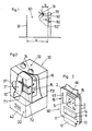
- a control station 70 (Fig. 1) is used for optional communication with active data carriers 50 and passive data carriers 50 'within a physical or even imaginary boundary 61 having detection space 60, the dimensions of which are provided with the data carrier 50, 50' object 51 (person or object) is coordinated.
- the detection space 60 can form a person passage lane with the size a, by which the boundary 61 is distanced from the control station 70.
- the control station 70 thus comprises two control devices 31, 32 which are accommodated in a common housing 30.
- the first control device 32 reads passive data carriers 50 ', in particular magnetic cards, punch cards, cards with bar codes etc., which are intended for one-time access, such as single trips or the like. They are inserted into the first control device 32 of the control station 70 in a conventional manner.
- passive data carrier 50 ' is only indicated by dashed lines in Fig. 1.
- the read data are fed to evaluation electronics 46.
- a print head 44 is also provided so that the control can be made visually visible. If data are also to be changed in a passive data carrier 50, a read / write head 43 (FIG. 7) is provided, with changes being made visible by the print head 44.
- the second control device 31 is provided for communication with active data carriers 50 which contain a microcomputer (FIGS. 5, 10), the data being transmitted to the second control device 31 by radio according to the first embodiment shown in FIGS. 2 to 5 .
- the transmit-receive frequencies are preferably in a range of 100 kHz and below.
- magnetic antennas can also be used for transmitter 15 and receiver 16, so that no undesired shielding effects occur.
- the low transmission energy limits the communication space to an environment 80 of the control station 70.
- the data carrier 50 Since the environment 80 has a maximum extension b, which is significantly smaller than the size a of the detection area, the data carrier 50 must be brought into the environment 80 of the control station 70 for the data transmission between the active data carrier 50 and the second control device. This means that the object 51 approaches the control station 70 to such an extent that a communication fault is accidentally or deliberately present in the detection area 60 other media is practically excluded. If the dimension a is 50 to 70 cm, for example, a suitable maximum extension b of the surrounding area 80 will be approximately 10 to 30 cm.
- the transmitting antennas 71, 48 and the receiving antenna 72, 49 are offset from one another by 90 ° both in the second control device 31 of the control station 70 (FIG. 2) and in the data carrier 50 (FIG. 3) , so that they do not influence each other magnetically. Due to the small extent b of the communication space, the formation of directionally independent antennas is generally unnecessary. However, it would be entirely conceivable to provide two receiving coils 72, 49 offset from one another in the control station 70 and / or in the data carrier 50. On the back, the housing 30 is provided with a shield 73.
- the control station 70 sends out an identification number with a carrier frequency fo (eg 100 kHz).
- a carrier frequency fo eg 100 kHz
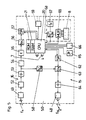
- the central unit 75 (CPU) of the control station transfers corresponding data into a shift register 76 (SR), from which these are read out serially in an encoder 77.
- the encoder 77 is connected to an oscillator 74 for the carrier frequency fo.
- the transmission antenna 71 is operated via corresponding amplifiers 78.
- the signals emitted by the control station 70 are received (FIG. 5) in the data carrier 50 by the receiving antenna 49 tuned to the carrier frequency fo.
- the signals are transmitted via a limiter 52 and an amplifier 53 a low-pass filter 54, which in turn is connected to a decoder 56.
- a timer 55 (t) is arranged between the low-pass filter 54 and the decoder 56, which prevents signals which are received accidentally from “waking up” the processor 20 (CPU) in the data carrier 50.
- the decoder 56 transfers the decoded data to a shift register 57 (SR), which wakes up the processor 20 via an interrupt, so that it can take over the read recognition received.
- SR shift register 57
- the processor 20 converts the read recognition using a defined algorithm and now in turn sends an additional data carrier number to the control station 70.
- the data carrier 50 requires the carrier frequency fo for the transmission traffic. This is via a frequency divider 58 (fo / fo 2nd ) fed to an encoder 63, which receives the corresponding data via a shift register 62 (SR) in front of processor 20.
- the transmission frequency is now fo / 2.
- This circuit has the advantage that no separate, constant oscillator is required in the data carrier 50, which oscillator must be matched to the control station 70.
- the signals pass through an amplifier 64 and transmitting antenna 48 of the data carrier 50 to the receiving antenna 72 of the second control device of the control station 70. From there they are fed to a decoder 83 via an amplifier 81 and a low-pass filter 82.
- the data arrive in the shift register 84 from the decoder to the central unit 75.
- the central unit 75 converts the received data using the same algorithm as the data carriers 50 and can thus identify any attempts at manipulation, with the transmission oscillator 74 being assigned a frequency divider 79.
- the same transmission frequency fo / 2 coming from the data carrier 50 can thus be compared directly.
- the respective real partner can interrupt the data transmission for a certain time or for a long time after a certain number of transmission attempts.
- control station 70 and the data carrier 50 are mutually recognized, the authenticity of both partners having been checked at the same time, so that the actual data traffic can take place, which is dependent on the specific application.
- control station 70 activates itself for the next application and calls again with its identifier until the next response is received from a subsequent data carrier 50.
- the processor 20 of the data carrier is normally in sleep mode, that is to say an inactive operating mode with minimal power consumption. It only takes action when valid data is received.
- a keyboard 66 for example for computing functions, for entering a personal identification number (PIN), etc. This enables certain actions to be made dependent on the input of the identification number.
- PIN personal identification number
- the data carrier 50 has its own switchover in order to enable minimal power consumption in inactive operation.
- This circuit consists of a clock oscillator 67, (fx), a programmable divider 68 (fn / fx) and a multiplexer 69 (MUX) for the LCD display 8. Program inaccuracies can be compensated for.
- the memory of processor 20 advantageously has a relatively small ROM area and a relatively large RAM area (e.g. 1 kb and 4 kb).
- the modules of the data carrier 50 described are advantageously integrated in a single chip, with the exception of the crystals, the LCD display 8 and the transmitter / receiver antennas 48, 49 and some peripheral components.
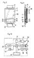
- FIG. 7 shows a second embodiment of a control station 70, the second control device 31 of which is provided for infrared data transmission. It contains a transmitting diode 27 and a receiving diode 47, an infrared filter 45, a control 35 and evaluation electronics 38, as well as the two-colored traffic light 33 with a red and a green lamp 34.
- the transmitting and receiving diodes 27, 47, the colored lamps 34 and a front optics 36 are accommodated in a receiving space 29, which is covered on the outside by a frosted glass pane 37.
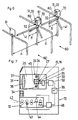
- 50 'of Similar signals emitted to the evaluation electronics 38, 46 are passed on to the traffic lights 33 and other connected peripheral devices such as a computer, a barrier, a turnstile 41, etc., via a changeover switch 39. 6 shows the latter in the example of a two-lane slide control station.
- 8 to 10 show an embodiment of an active data carrier for optical data transmission, in particular medium infrared waves.
- the electronics contained in the data carrier 50 can be seen in the block diagram from FIG. 10.
- the central microprocessor 20 (.mu.c) is connected to infrared transmission diodes as transmitter 15 with associated transmission logic 18, with an infrared reception diode as receiver 16 with associated reception logic 19 to which standby logic 17 is assigned, and to a current source 7, the current source 7, in particular if it is formed by a battery, is provided with a control logic 22.
- the data to be entered into the data carrier 50 are stored in a read-write memory 21, in particular an EEPROM or RAM, and can be made visible on a liquid crystal display 8 by pressing a button 13.
- the current source 7 can also be a rechargeable battery or a solar cell.
- Each active data carrier 50 has a housing which consists of a lower part 1 and an upper part 2 (FIGS. 3, 8, 9).
- the housing is in particular made of plastic, wherein the two parts 1, 2 are preferably welded together.
- the lower part 1 of the housing can be in various embodiments. As shown, receptacles for a bracelet 12 are provided on the lower part 1, so that an active data carrier 50, similar to a watch, can be worn on the forearm or wrist (object 51, FIG. 1).
- the lower part 1 can also be provided with a clip be and carry an additional labeling field.
- the housing can also be designed as a key fob, a cord attached to a key ring being wound on a spring roller in the lower part.
- the lower part 1 can also be provided with a self-adhesive layer. The latter two versions are primarily intended for vehicles (parking garages, toll stations, etc.).
- the upper part 2 has a socket 28 for a photo 5 or the like, which is closed by a cover 3.
- the cover 3 carries on the inside an adhesive coating 4 to which the photo 5 is glued.
- the type of adhesive is chosen so that when the photo 5 is detached, it is destroyed, and thus the exchange for another photo becomes visible.
- Under the cover 3, a cover 11 is inserted into the upper part 2, under which the liquid crystal display 8 is arranged.
- the transmitter 15 and the receiver 16 are provided for receiving and delivering the data.
- the key 13 serves to visualize the data contained in the data carrier 50 on the display 8.
- On the display 8 there is also a number field 14 with a visually readable, individual number, which can be stamped or printed, for example.
- the same "serial number" can also be provided on cover 3 or on photo 5.
- the display 8 is fed in the usual way at the push of a button via contacts 10 by a chip 9 which is arranged on a substrate.
- the power supply comes from a power source 7, for example a battery, a solar cell, etc.
- the data carrier forms a multi-trip card or point card, not only is the validity checked in the control station 70, but a partial validation is carried out.
- the additional storage of its individual number is of particular advantage, since the second control device of the control station can also be used to keep records of the continuous cancellation, if this is connected to a computer, and the respective data to a number journal be transmitted. Since the active data carrier 50 contains a microcomputer, information and functions can be freely divided between the data carrier 50 and the control station 70, which complement one another or possibly also overlap.
Landscapes
- Engineering & Computer Science (AREA)
- Physics & Mathematics (AREA)
- General Physics & Mathematics (AREA)
- Theoretical Computer Science (AREA)
- Business, Economics & Management (AREA)
- Computer Vision & Pattern Recognition (AREA)
- Artificial Intelligence (AREA)
- Electromagnetism (AREA)
- Microelectronics & Electronic Packaging (AREA)
- Computer Hardware Design (AREA)
- Accounting & Taxation (AREA)
- Finance (AREA)
- Health & Medical Sciences (AREA)
- General Health & Medical Sciences (AREA)
- Toxicology (AREA)
- Strategic Management (AREA)
- Computer Networks & Wireless Communication (AREA)
- General Business, Economics & Management (AREA)
- Devices For Checking Fares Or Tickets At Control Points (AREA)
- Selective Calling Equipment (AREA)
- Cash Registers Or Receiving Machines (AREA)
- Communication Control (AREA)
- Exchange Systems With Centralized Control (AREA)
- Error Detection And Correction (AREA)
- Near-Field Transmission Systems (AREA)
- Optical Communication System (AREA)
- Mobile Radio Communication Systems (AREA)
Abstract
Description
Die Erfindung betrifft eine Kontrollstation zur Überprüfung von Daten in Datenträgern, insbesondere bei der Kontrolle einer Zutrittsberechtigung oder dergleichen, mit einer Kontrolleinrichtung zum Lesen von einzusteckenden, passiven Datenträgern, auf denen die Daten in beispielsweise magnetischer oder optischer Form gespeichert sind, wobei das Kontrollergebnis an zumindest eine periphere Einrichtung, insbesondere an eine Zutrittssperre weitergeleitet wird. Derartige Kontrollstationen werden für verschiedene Verwendungszwecke eingesetzt, etwa an Schiliftanlagen, zum Überprüfen oder Entwerten von Fahrkarten, in Parkgaragen zur Freigabe der Einfahrt oder Ausfahrt etc. Das Einschieben der passiven Datenträger, vorwiegend Magnetkarten, Strichcodekarten, auch Lochkarten usw., in den Aufnahmeschlitz eines Lesegerätes der Kontrollstation erfordert einen relativ hohen Zeitaufwand und verursacht den Benützern Unannehmlichkeiten bei der Handhabung.The invention relates to a control station for checking data in data carriers, in particular when checking an access authorization or the like, with a control device for reading passive data carriers to be inserted, on which the data are stored in magnetic or optical form, for example, the control result being at least a peripheral device, in particular forwarded to an access block. Such control stations are used for various purposes, for example on ski lifts, for checking or validating tickets, in parking garages to enable entry or exit etc. The insertion of passive data carriers, mainly magnetic cards, bar code cards, also punch cards etc., into the slot of a reader the control station requires a relatively large amount of time and causes user inconvenience in handling.
Eine derartige Kontrollstation ist beispielsweise der CA-A-1184658 zu entnehmen. Sie dient zur Kontrolle von mit einem abreißbaren Kontrollabschnitt versehenen, üblichen Eintrittskarten, auf denen zwei verschiedene, maschinenlesbare Datencodes vorgesehen sind, von denen einer sichtbar und der zweite zur Erschwerung von Fälschungen unsichtbar bzw. verdeckt angebracht ist. Die Eintrittskarten werden durch einen Aufnahmeschlitz in die Kontrollstation eingeschoben, in der zwei Datenleseeinrichtungen enthalten sind. Die gelesenen Daten werden verglichen, und bei Übereinstimmung der sichtbaren und der unsichtbaren Daten wird die Eintrittskarte als gültig betrachtet, der Kontrollabschnitt abgerissen, und die Eintrittskarte an den Benützer retourniert. Die gültige Eintrittskarte schaltet in der Folge eine Ampel auf grün und öffnet ein Drehkreuz. Wird durch fehlende Übereinstimmung eine Fälschung erkannt, blinkt einr rotes Licht der Ampel, ein Alarm ertönt und die gefälschte Karte wird wieder ausgeworfen.Such a control station can be found, for example, in CA-A-1184658. It is used to check conventional admission cards with a tear-off control section, on which two different, machine-readable data codes are provided, one of which is visible and the other is attached invisibly or concealed to make counterfeiting more difficult. The admission tickets are inserted through a slot into the control station, which contains two data reading devices. The data read is compared, and if the visible and invisible data match, the admission ticket is considered valid, the control section is torn down, and the admission ticket is returned to the user. The valid admission ticket then turns a traffic light to green and opens a turnstile. Is due to mismatch if a forgery is detected, the red light of the traffic light flashes, an alarm sounds and the counterfeit card is ejected again.
Es sind insbesondere für die Personenidentifizierung auch aktive Datenträger bekannt, wobei der Datenträger selbst elektronische Bauteile, wie Rechner, Display usw. enthält. Biespiele dafür zeigen die EP-B-19280 (Ausweiskarte mit elektrischen Kontaktflächen), die EP-A-142013 (Datentäger mit induktiver Datenübertragung) und Zerstörung der Daten bei mechanischem Eingriff), EP-A-168836 (Datenkarte für Geldausgabeautomaten mit optischer Datenübertragung), die EP-A-196028 (Wertkarte mit elektrischen Kontaktflächen) und die WO-A-86/04705 (Telefonwertkarte mit induktiver Datenübertragung).Active data carriers are also known, in particular for personal identification, the data carrier itself containing electronic components such as computers, displays, etc. Examples of this are shown in EP-B-19280 (identification card with electrical contact surfaces), EP-A-142013 (data carrier with inductive data transmission) and destruction of the data in the event of mechanical intervention), EP-A-168836 (data card for automated teller machines with optical data transmission) , EP-A-196028 (prepaid card with electrical contact surfaces) and WO-A-86/04705 (prepaid telephone card with inductive data transmission).
Alle diese Datenträger müssen ebenfalls in einen Aufnahmeteil der Kontrolleinrichtung eingesetzt werden, sodaß sich hinsichtlich der Handhabung keine Vorteile gegenüber den passiven Datenträgern ergeben. Weitere aktive Datenträger sind mit Sende-Empfangseinrichtungen für eine distanzierte Kommunikation zwischen den Datenträgern und der Kontrolleinrichtung ausgebildet. Beispiele dafür geben die EP-A-61373, die US-A-4325146 und die US-A-4338587.All of these data carriers must also be inserted into a receiving part of the control device, so that there are no advantages over passive data carriers with regard to handling. Further active data carriers are designed with transceivers for distant communication between the data carriers and the control device. Examples of this are given by EP-A-61373, US-A-4325146 and US-A-4338587.
Die ebenfalls eine Sende-Empfangseinheit umfassende Kontrollstation der EP-A-61373 überprüft Datenträger bei der Kontrolle einer Zutrittsberechtigung zu Schiliften od. dgl. Bei berechtigtem Zutritt wird beispielsweise ein Drehkreuz einer Durchgangsspur freigegeben. Die Datenübertragung findet dabei insbesondere mittels Ultraschall statt.The control station of EP-A-61373, which also comprises a transceiver unit, checks data carriers when checking access authorization to ski lifts or the like. When access is authorized, for example, a turnstile of a through lane is released. The data transmission takes place in particular by means of ultrasound.
Die US-A-4325146 zeigt ein in ähnlicher Weise arbeitendes Kontrollsystem. Hier wird eine optische Datenübertragung zwischen einer Kontrollstation und sich nähernden Fahrzeugen bzw. den in den Fahrzeugen vorhandenen Datenträgern vorgenommen, etwa an der Einfahrt zur Parkfläche. Berechtigte Fahrzeuge können damit ahne anzuhalten einen sich rechtzeitig öffnenden Schranken passieren. Die Kontrolle ist damit wesentlich beschleunigt.US-A-4325146 shows a control system operating in a similar manner. Here there is an optical data transmission between a control station and approaching vehicles or the data carriers present in the vehicles made, for example at the entrance to the parking area. Authorized vehicles can thus pass a barrier that opens in time without stopping. The control is accelerated considerably.
Die im Vergleich zu Magnet- oder Lochkarten wesentlich teureren aktiven Datenträger lassen sich in der Massenanwendung für Zutritte mit geringem Wert vor allem wegen der hohen Kosten nicht ohne weiters verwenden. Beispielsweise für Einzelfahrkarten an Schiliften werden sie vom Publikum nicht akzeptiert. Gerade dort sind bisherige Kontrolleinrichtungen unumgänglich, obwohl eine Kontrolle aktiver Datnträger die Leistungsfähigkeit der Kontrollstation wesentlich erhöhen würde.The active data carriers, which are much more expensive than magnetic or punched cards, cannot easily be used in mass applications for low-value access, primarily because of the high costs involved. For example, for single tickets on ski lifts they are not accepted by the public. Existing control devices are inevitable there, although a check of active data carriers would significantly increase the performance of the control station.
Die Gestehungskosten aktiver Datenträger macht aber deren Einsatz für die Zutrittskontrolle mit einem geringen Wert eines einmaligen oder gelegentlichen Zutritts unwirtschaftlich, sodaß etwa für die Mauteinhebung an Autobahnen, gemäß der US-A-4338587 Kontrolleinrichtungen für aktive, am Fahrzeug vorgesehene Datenträger mit herkömmlichen Inkassoeinrichtungen kombiniert sind. Dabei sind für jede Art der Kontrolle eigene Peripheriegeräte vorgesehen. Während ein positives Kontrollergebnis der aktiven Datenträger keine Peripheriegeräte ansteuert, werden bei negativem Kontrollergebnis Halte- und Warneinrichtungen betätigt. Beim üblichen Inkasso hingegen wird nach der Barzahlung die öffnung eines Schrankens bewirkt.However, the production costs of active data carriers make their use for access control with a low value of a one-off or occasional access uneconomical, so that, for example, for toll collection on highways, control devices for active data carriers provided on the vehicle are combined with conventional collection facilities in accordance with US-A-4338587 . Separate peripheral devices are provided for each type of control. While a positive control result of the active data carriers does not control peripheral devices, holding and warning devices are actuated in the event of a negative control result. With normal debt collection, however, a barrier is opened after the cash payment.
Die Erfindung hat es sich nun zur Aufgabe gestellt eine Kontrollstation der eingangs genannten Art, in der ein positives Kontrollergebnis den gesperrten Zu- oder Durchgang freigibt, für die Kontrolle passiver und aktiver Datenträger auszubilden, sodaß für alle Benützer die Wartezeit verringert und der Komfort erhöht wird.The invention has now set itself the task of a control station of the type mentioned, in which a positive control result releases the blocked access or passage, for the control of passive and active data carriers, so that the waiting time is reduced and the comfort is increased for all users .
Erfindungsgemäß wird dies nun dadurch gelöst, daß die Kontrollstation eine zweite Kontrolleinrichtung aufweist, die eine Sende-Empfangseinheit für eine distanzierte Kommunikation mit angenäherten aktiven Datenträgern umfaßt, in denen ebenfalls eine Sende-Empfangseinheit enthalten ist, und daß die beiden Kontrolleinrichtungen parallele Ausgänge aufweisen, deren mittels des wahlweise verwendeten Datenträgers erzeugte Ausgangssignale über einen Umschalter die peripheren Einrichtungen ansteuern.According to the invention, this is now achieved in that the control station has a second control device, which comprises a transceiver unit for distant communication with approximate active data carriers, in which a transceiver unit is also included, and that the two control devices have parallel outputs, the Output signals generated by means of the optionally used data carrier control the peripheral devices via a changeover switch.
Der Benützer kann dabei die Art des Datenträgers wählen und die zu kontrollierenden Daten werden in einer Initialisierungsstation in die jeweiligen Datenträger eingespeichert. Aktive Datenträger sind durch Löschen und Eingabe neuer Daten wiederholt verwendbar. Sie können daher etwa als Jahreskarten, Dauerausweise für sich wiederholende Veranstaltungen usw. eingesetzt werden, wobei in der zugehörigen, zweiten Kontrolleinrichtung der Kontrollstation nur das Gültigkeitsdatum überprüft werden muß, das bei der Wiederverwendung nach Ablauf wieder neu eingespeichert wird. Wird in der zweiten Kontrolleinrichtung auch eine fortlaufende Entwertung durchgeführt, bis ein dem Kaufpreis entsprechender "Vorrat" aufgebraucht ist, so lassen sich die Datenträger auch als Mehrfahrtenkarte, als Entrittskarte für Veranstaltungen mit Konsummöglichkeit (Gastgewerbe, Vergnügungs- und Freizeitanlagen) usw. verwenden. Vorteilhaft wird bei dieser Ausführung eine Restwertanzeige über ein Display sichtbar gemacht werden können, wobei dieser Restwert sich nach dem jeweiligen Verwendungszweck richtet, beispielsweise Anzeige des Ablaufdatums, Anzeige nach der vorletzten Fahrt einer Mehrfahrtenkarte od. dgl., um eine rechtzeitige Wiederaufwertung in einer Initialisierungsstation zu ermöglichen. Ein derartiger Datenträger könnte auch mit Pfand ausgegeben, bzw. nach seiner Verwendung wieder zurückgekauft werden, und ist auch für die Massenanwendung wirtschaftlich, da die Gestehungskosten nur einen akzeptablen Prozentsatz des verkörperten Wertes betragen.The user can select the type of data carrier and the data to be checked are stored in the respective data carriers in an initialization station. Active data carriers can be used repeatedly by deleting and entering new data. They can therefore be used, for example, as annual cards, permanent ID cards for repetitive events, etc., only the validity date having to be checked in the associated, second control facility of the control station, which is then re-stored when it is reused after expiry. If in the second control facility a continuous devaluation is carried out until a "supply" corresponding to the purchase price has been used up, the data carriers can also be used as multi-trip tickets, as entry tickets for events with consumption options (hospitality, entertainment and leisure facilities) etc. In this embodiment, a residual value display can advantageously be made visible on a display, this residual value depending on the respective intended use, for example display of the expiry date, display after the penultimate trip of a multi-trip card or the like, in order to enable timely re-evaluation in an initialization station enable. Such a data carrier could also be issued with a deposit, or after its use be bought back again, and is also economical for mass use, since the production costs are only an acceptable percentage of the embodied value.
Für die Identifizierung bzw. die Zutrittsfreigabe muß der auf Entfernung lesbare Datenträger nur in den Kontrollbereich der Sende-Empfangseinheit der zweiten Kontrolleinrichtung gebracht werden, wo in einer sehr kurzen Zeitspanne, vorzugsweise unter 1 Sekunde, die Berechtigung und/oder die Gültigkeit der Berechtigung überprüft wird.For identification or access approval, the data carrier, which can be read at a distance, only has to be brought into the control area of the transceiver unit of the second control device, where the authorization and / or the validity of the authorization is checked in a very short period of time, preferably under 1 second .
Für Dienstleistungen mit geringem Wert, für die auch eine Ausgabe mit Pfand bzw. ein Rückkauf keine Vorteile bringt, beispielsweise einmalige Eintrittskarte, Einzelfahrkarte, Kurzzeitparkgaragenkarte usw. werden weiterhin die passiven Datenträger verwendet, die in die zugehörige, erste Kontrolleinrichtung eingesteckt, gelesen und bei positivem Kontrollergebnis weggeworfen werden. Die über den Umschalter angeschlossenen gemeinsamen Peripheriegeräte, beispielsweise eine Ampel, ein Schranken, ein Drehkreuz, bzw. ein zentraler Rechner für die Abrechnung, usw. sprechen auf jedes positive Kontrollergebnis an.For services with low value, for which an issue with a deposit or a buyback does not have any advantages, for example a one-time entry ticket, single ticket, short-term parking garage card, etc., the passive data carriers are still used, which are inserted into the associated first control device, read and if positive Control result to be thrown away. The common peripheral devices connected via the changeover switch, for example a traffic light, a barrier, a turnstile, or a central computer for billing, etc., respond to any positive control result.
Da die Kontrolle von Benützern mit aktiven Datenträgern rascher erfolgt, ist leicht ersichtlich, daß damit der Durchgang durch die Kontrollstation für die in Reihe wartenden Benützer wesentlich beschleunigt und Wartezeiten reduziert werden. Die Zeitersparnis wird beispielsweise bei Autobahnmautstellen oder Schiliften besonders augenscheinlich.Since the control of users with active data carriers takes place more quickly, it is easy to see that the passage through the control station for the users waiting in line is considerably accelerated and waiting times are reduced. The time saved is particularly evident, for example, at motorway tollbooths or ski lifts.
Da von den Kontrolleinrichtungen gemeinsame Peripheriegeräte angesteuert werden, sind in einer vorteilhaften Ausführung beide Kontrolleinrichtungen auch in einem gemeinsamen Gehäuse angeordnet.Since common peripheral devices are controlled by the control devices, in an advantageous embodiment both control devices are also arranged in a common housing.
Eine besonders platzsparende, nach außen abgekapselte Konstruktion läßt sich weiters noch dadurch verwirklichen, daß eine der peripheren Einrichtungen eine im Gehäuse angeordnete mehrfärbige Ampel zur Anzeige des Kontrollergebnisses umfaßt, wobei die Sende-Empfangseinheit der zweiten Kontrolleinrichtung und die Lampen der Ampel von einer gemeinsamen Abdeckung aus mattiertem Glas überdeckt sind.A particularly space-saving, externally encapsulated construction can also be realized in that one of the peripheral devices comprises a multi-colored traffic light arranged in the housing for displaying the control result, the transceiver unit of the second control device and the lamps of the traffic light from a common cover frosted glass are covered.
Die Sende-Empfangseinheit der zweiten Kontrolleinrichtung für Funkübertragung mit einem bevorzugten Trägerfrequenzbereich bis 250 kHz ausgelegt, sodaß nur geringe Sendeenergie benötigt wird. Dies ist vor allem für die Energieversorgung der aktiven Datenträger wesentlich. Um die wechselweise Kommunikation zwischen der zweiten Kontrolleinrichtung und den aktiven Datenträgern nicht störend zu beeinflussen, sieht eine bevorzugte Ausführung vor, daß die Trägerfrequenzen für die Datenübertragung von der Kontrollstation zum Datenträger sowie vom Datenträger zur Kontrollstation unterschiedlich sind, wobei die Sende-Empfangseinheit der Kontrollstation einen Sendeoszillator und die Sende-Empfangseinheit des Datenträgers einen Frequenzteiler enthält.The transceiver unit of the second control device is designed for radio transmission with a preferred carrier frequency range up to 250 kHz, so that only low transmission energy is required. This is particularly important for the energy supply of the active data carriers. In order not to interfere with the alternating communication between the second control device and the active data carriers, a preferred embodiment provides that the carrier frequencies for the data transmission from the control station to the data carrier and from the data carrier to the control station are different, the transceiver unit of the control station being one Transmitting oscillator and the transceiver unit of the data carrier contains a frequency divider.
Der Kommunikationsraum der zweiten Kontrolleinrichtung wird dabei wesentlich kleiner als das zu erfassende Objekt, sodaß eine Datenübertragung nur innerhalb eine beschränkten Umfeldes der zweiten Kontrolleinrichtung erfolgen kann. Damit kann die zufällige Anwesenheit eines nicht anzusprechenden, aktiven Datenträgers mit Sicherheit ausgeschlossen und eine mutwillige Störung zumindest wesentlich erschwert werden. Dennoch ist eine bewußte und gewollte Handhabung des aktiven Datenträgers notwendig, die hinsichtlich der Aktivität des Benützers mit dem Einstecken eines passiven Datenträgers in einen Aufnahmeschlitz vergleichbar ist.The communication space of the second control device becomes significantly smaller than the object to be detected, so that data can only be transmitted within a limited environment of the second control device. In this way, the accidental presence of an active data carrier that cannot be addressed can be ruled out with certainty and a willful disturbance can at least be made considerably more difficult. Nevertheless, conscious and intentional handling of the active data carrier is necessary, which is comparable in terms of the activity of the user to inserting a passive data carrier into a slot.
Für einen Personenerfassungsraum, etwa eine vereinzelnde Personendurchgangsspur, ist die größte Erstreckung des Kommunikationsraumes senkrecht zur Spur beispielsweise mit 10 cm bis 30 cm, vorzugsweise mit 20 cm vorgesehen, und für eine fahrzeugvereinzelnde Fahrspur kann diese zwischen 50 cm und 200 cm vorzugsweise 100 cm betragen.For a person detection area, such as a single passage lane, the largest extent of the communication space perpendicular to the lane is provided, for example, with 10 cm to 30 cm, preferably 20 cm, and for a vehicle lane, this can be between 50 cm and 200 cm, preferably 100 cm.
In einer anderen Ausführung ist die Datenübertragung mittels Lichtwellen vorgesehen, wobei hier insbesondere der Infrarotbereich gewählt wird; es könnte jedoch auch Laserlicht eingesetzt werden. Auch bei der Datenübertragung mittels Lichtwellen ist der begrenzte Übertragungsbereich gegen Fremdeinflüsse ohne besonderen Aufwand abschirmbar. So kann dies mittles einer mit Abstand zu Sender und Empfänger vorgesehenen Begrenzungsblende für den Erfassungsraum erfolgen.In another embodiment, data transmission by means of light waves is provided, the infrared region in particular being selected here; however, laser light could also be used. The limited transmission range can also be shielded against external influences without any special effort when data is transmitted by means of light waves. This can be done by means of a delimitation diaphragm for the detection area which is provided at a distance from the transmitter and receiver.
In einer weiteren Ausführung ist vorgesehen, daß die Kontrolleinrichtung zum Lesen der passiven Datenträger im Anschluß an den Einsteckschlitz einen Schreib-Lesekopf und einen Druckkopf enthält. Dadurch können Änderungen der magnetischen oder optischen Kennzeichnung bzw. mehrfache Verwendungen des passiven Datenträgers auch visuell sichtbar auf ihn aufgedruckt werden.In a further embodiment it is provided that the control device for reading the passive data carriers contains a read / write head and a print head following the insertion slot. As a result, changes in the magnetic or optical marking or multiple uses of the passive data carrier can also be visually printed on it.
Nachstehend wird nun die Erfindung an Hand der Figuren der beiliegenden Zeichnungen näher beschrieben, ohne darauf beschränkt zu sein.The invention will now be described in more detail below with reference to the figures in the accompanying drawings, without being limited thereto.
Es zeigen:
- Fig. 1 eine schematische Darstellung einer Kontrollstation mit zwei Kontrolleinrichtungen,
- Fig. 2 eine erste Ausführung einer Kontrollstation mit schematischem Teilschnitt der zweiten Kontrolleinrichtung,
- Fig. 3 eine erste Ausführung eines aktiven Datenträgers zur Kommunikation mit der Kontrollstation nach Fig. 2,
- Fig. 4 ein Blockschaltbild der zweiten Kontrolleinrichtung der Kontrollstation nach Fig. 2,
- Fig. 5 ein Blockschaltbild des Datenträgers nach Fig. 3,
- Fig. 6 eine zweispurige Kontrollanlage mit Sperren,
- Fig. 7 einen schematischen Schnitt durch eine zweite Ausführung einer Kontrollstation,
- Fig. 8 eine zweite Ausführung eines aktiven Datenträgers zur Kommunikation mit der Kontrollstation nach Fig. 7,
- Fig. 9 einen Längsschnitt durch den Datenträger nach Fig. 8, und
- Fig. 10 ein Blockschaltbild des Datenträgers nach Fig. 8.
- 1 is a schematic representation of a control station with two control devices,
- 2 shows a first embodiment of a control station with a schematic partial section of the second control device,
- 3 shows a first embodiment of an active data carrier for communication with the control station according to FIG. 2,
- 4 shows a block diagram of the second control device of the control station according to FIG. 2,
- 5 is a block diagram of the data carrier of FIG. 3,
- 6 is a two-lane control system with locks,
- 7 shows a schematic section through a second embodiment of a control station,
- 8 shows a second embodiment of an active data carrier for communication with the control station according to FIG. 7,
- 9 shows a longitudinal section through the data carrier according to FIG. 8, and
- 10 shows a block diagram of the data carrier according to FIG. 8.
Eine Kontrollstation 70 (Fig. 1) dient der wahlweisen Kommunikation mit aktiven Datenträgern 50 und passiven Datenträgern 50′ innerhalb eines eine körperliche oder auch nur gedachte Begrenzung 61 aufweisenden Erfassungsraumes 60, der in seinen Dimensionen auf das mit dem Datenträger 50, 50′ versehene Objekt 51 (Person oder Gegenstand) abgestimmt ist. So kann der Erfassungsraum 60 beispielsweise eine Personendurchgangsspur mit der Größe a bilden, um die die Begrenzung 61 von der Kontrollstation 70 distanziert ist.A control station 70 (Fig. 1) is used for optional communication with
Die Kontrollstation 70 umfaßt somit zwei Kontrolleinrichtungen 31, 32, die in einem gemeinsamen Gehäuse 30 untergebracht sind. Die erste Kontrolleinrichtung 32 liest passive Datenträger 50′, insbesondere Magnetkarten, Lochkarten, Karten mit Strichcode etc., die für einmalige Zutritte, wie Einzelfahrten od. dgl. gedacht sind. Sie werden in die erste Kontrolleinrichtung 32 der Kontrollstation 70 in herkömmlicher Weise eingeschoben. Ein derartiger passiver Datenträger 50′ ist in Fig. 1 nur strichliert angedeutet. Die gelesenen Daten werden gemäß Fig. 7 einer Auswerteelektronik 46 zugeführt. Weiters ist ein Druckkopf 44 vorgesehen, sodaß die Kontrolle visuell sichtbar gemacht werden kann. Falls auch in einem passiven Datenträger 50′ Daten geändert werden sollen, ist ein Schreib-Lesekopf 43 (Fig. 7) vorgesehen, wobei vom Druckkopf 44 auch Änderungen sichtbar gemacht werden.The
Die zweite Kontrolleinrichtung 31 ist zur Kommunikation mit aktiven Datenträgern 50 vorgesehen, die einen Mikrocomputer (Fig. 5, 10) enthalten, wobei gemäß der in den Fig. 2 bis 5 näher gezeigten ersten Ausführung die übertragung der Daten zur zweiten Kontrolleinrichtung 31 mittels Funk erfolgt. Die Sende-Empfangsfrequenzen liegen vorzugsweise in einem Bereich von 100 kHz und darunter. Dadurch können auch magnetische Antennen für Sender 15 und Empfänger 16 verwendet werden, sodaß keine unerwünschten Abschirmeffekte auftreten. Die geringe Sendeenergie beschränkt den Kommunikationsraum auf ein Umfeld 80 der Kontrollstation 70.The
Da das Umfeld 80 eine maximale Erstreckung b aufweist, die wesentlich kleiner als die Größe a des Erfassungsraumes ist, muß für die Datenübertragung zwischen dem aktiven Datenträger 50 und der zweiten Kontrolleinrichtung der Datenträger 50 ins Umfeld 80 der Kontrollstation 70 gebracht werden. Dieses bedeutet somit eine Annäherung des Objektes 51 an die Kontrollstation 70 in einem Ausmaß, daß eine Störung der Kommunikation durch einen zufällig oder auch absichtlich im Erfassungsraum 60 anwesenden anderen Datenträger praktisch ausgeschlossen ist. Liegt das Maß a beispielsweise bei 50 bis 70 cm, so wird eine geeignete maximale Erstreckung b des Umfeldes 80 etwa 10 bis 30 cm betragen.Since the
Wie aus Fig. 2 und 3 ersichtlich, sind die Sendeantennen 71,48 und die Empfangsantenne 72, 49 sowohl in der zweiten Kontrolleinrichtung 31 der Kontrollstation 70 (Fig. 2) als auch im Datenträger 50 (Fig. 3) um 90° gegeneinander versetzt, sodaß sie sich magnetisch nicht beeinflussen. Auf Grund der geringen Erstreckung b des Kommunikationsraumes erübrigt sich im allgemeinen die Ausbildung richtungsunabhängiger Antennen. Es wäre aber durchaus denkbar, zwei gegeneinander versetzte Empfangsspulen 72, 49 in der Kontrollstation 70 und/oder im Datenträger 50 vorzusehen. Rückseitig ist das Gehäuse 30 mit einer Abschirmung 73 versehen.As can be seen from FIGS. 2 and 3, the transmitting
Anhand der beiden in den Fig. 4 und 5 gezeigten Blockschaltbilder der zweiten Kontrolleinrichtung 31 der Kontrollstation 70 und des Datenträgers 50 wird nachstehend die Kommunikation zwischen der Kontrollstation und dem ins Umfeld 80 angenäherten Datenträger 50 näher erläutert.4 and 5 of the
Die Kontrollstation 70 sendet mit einer Trägerfrequenz fo (z.B. 100 kHz) eine Kennummer aus. (Fig. 4) Hiezu überträgt die Zentraleinheit 75 (CPU) der Kontrollstation entsprechende Daten in ein Schieberegister 76 (SR), aus welchen diese seriell in einem Encoder 77 ausgelesen werden. Der Encoder 77 ist mit einem Oszillator 74 für die Trägerfrequenz fo verbunden. Über entsprechende Verstärker 78 wird die Sendeantenne 71 betrieben. Die von der Kontrollstation 70 abgegebenen Signale werden (Fig. 5) im Datentäger 50 von der auf die Trägerfrequenz fo abgestimmten Empfangsantenne 49 empfangen. Über einen Begrenzer 52 und einen Verstärker 53 werden die Signale einem Tiefpaß 54 zugeführt, der wiederum mit einem Decoder 56 verbunden ist.The
Zwischen dem Tiefpaß 54 und dem Decoder 56 ist ein Zeitglied 55 (t) angeordnet, welches verhindert, daß zufällig empfangene Signale den Prozessor 20 (CPU) im Datenträger 50 "aufwecken". Der Decoder 56 übergibt die decodierten Daten einem Schieberegister 57 (SR), welches über einen Interrupt den Prozessor 20 aufweckt, sodaß dieser die empfangene Leserkennung übernehmen kann.A timer 55 (t) is arranged between the low-
Der Prozessor 20 rechnet die Leserkennung mit einem festgelegten Algorithmus um, und sendet nun seinerseits zusätzlich eine eigene Datenträgernummer zur Kontrollstation 70 retour. Zum Sendeverkehr benötigt der Datenträger 50 die Trägerfrequenz fo. Diese wird über einen Frequenzteiler 58![]()
![]()
Vom Decoder gelangen die Daten in ein Schieberegister 84 zur Zentraleinheit 75. Diese rechnet die empfangenen Daten mit demselben Algorithmus wie die Datenträger 50 um und kann so etwaige Manipulationsversuche erkennen, wobei dem Sendeoszillator 74 ein Frequenzteiler 79 zugeordnet ist. Die vom Datenträger 50 kommende gleiche Sendefrequenz fo/2 kann somit direkt verglichen werden.The data arrive in the
Wird beispielsweise entweder die Kontrollstation 70 oder insbesondere der Datenträger 50 durch eine Fälschung simuliert, so kann der jeweilige, echte Partner nach einer bestimmten Anzahl von Übertragungsversuchen die Datenübertragung für bestimmte Zeit oder auf Dauer unterbrechen.If, for example, either the
Nach diesem ersten Datenverkehr sind die Kontrollstation 70 und der Datenträger 50 gegenseitig erkannt, wobei zugleich eine Überprüfung der Echtheit beider Partner stattgefunden hat, sodaß der eigentliche Datenverkehr erfolgen kann, der von der konkreten Anwendung abhängig ist. Nach Abschluß dieser Datenübermittlung schaltet sich die Kontrollstation 70 für den nächsten Anwendungsfall frei und ruft wieder mit seiner Kennung bis die nächste Antwort von einem folgenden Datenträger 50 empfangen wird.After this first data traffic, the
Wie bereits erwähnt, befindet sich der Prozessor 20 des Datenträgers normalerweise im Schlaf-Modus, also einer inaktiven Betriebsart mit minimalem Stromverbrauch. Er tritt nur dann in Aktion, wenn gültige Daten empfangen werden.As already mentioned, the
Weiters ist es möglich, den Prozessor 20 über eine eingebaute Taste 65 aufzuwecken, und beispielsweise den jeweiligen Status (Anzahl und Wert der eingespeicherten Berechtigungen), sowie die durchgeführten Transaktionen am Display anzuzeigen. (Fig. 5)Furthermore, it is possible to wake up the
Schließlich ist es noch möglich, eine Tastatur 66 beispielsweise für Rechenfunktionen, zur Eingabe einer persönlichen Identifizierungsnummer (PIN) etc. anzuschließen. Dadurch können bestimmte Aktionen von der Eingabe der Identifizierungsnummer abhängig gemacht werden.Finally, it is also possible to connect a
Es ist auch vorgesehen, über eine serielle Schnittstelle 59 mit dem Prozessor 20 in Verbindung zu treten.It is also provided via a
Der Datenträger 50 weist eine eigene Umschaltung auf, um im inaktiven Betrieb minimalen Stromverbrauch zu ermöglichen. Diese Schaltung besteht aus einem Uhrenoszillator 67, (fx), einem programmierbaren Teiler 68 (fn/fx) und einem Multiplexer 69 (MUX) für das LCD-Display 8. Programmgesteuert können Gangungenauigkeiten ausgeglichen werden.The
Der Speicher des Prozessors 20 hat vorteilhaft einen relativ kleinen ROM-Bereich und einen relativ großen RAM-Bereich (z.B. 1 kb und 4 kb).The memory of
Im ROM werden nur die grundsätzlichen Routinen zur Bedienung der Peripherie ― Module und zum Datenverkehr abgespeichert. Im RAM sind anwendungsspezifische Programme sowie alle Daten abgespeichert. Dadurch können Änderungen leicht durchgeführt werden und alle Transaktionen auch im nachhinein überprüft werden. Die beschriebenen Module des Datenträgers 50 sind mit Ausnahme der Quarze, des LCD-Displays 8 und der Sender/Empfangsantennen 48,49 sowie einigen Peripherie-Bausteinen vorteilhaft in einem einzigen Chip integriert.Only the basic routines for operating the peripheral modules and for data traffic are stored in the ROM. Application-specific programs and all data are stored in RAM. This means that changes can be made easily and all transactions can also be checked afterwards. The modules of the
In Fig. 7 ist eine zweite Ausführung einer Kontrollstation 70 gezeigt, deren zweite Kontrolleinrichtung 31 für eine Infrarot-Datenübertragung vorgesehen ist. Sie enthält eine Sendediode 27 und eine Empfangsdiode 47, einen Infrarotfilter 45, eine Ansteuerung 35 und eine Auswerteelektronik 38, sowie die zweifärbige Ampel 33 mit einer roten und einer grünen Lampe 34. Die Sende- und Empfangsdioden 27, 47, die färbigen Lampen 34 und eine vorgesetzte Optik 36 sind in einem Aufnahmeraum 29 untergebracht, der nach außen durch eine mattierte Glasscheibe 37 abgedeckt ist.FIG. 7 shows a second embodiment of a
Die je nach Art des zu prüfenden Datenträgers 50, 50′ von der Auswerteelektronik 38,46 abgegebenen gleichartigen Signale werden über einen Umschalter 39 an die Ampel 33 und andere angeschlossene Peripheriegeräte wie einen Rechner, einen Schranken, ein Drehkreuz 41 usw. weitergegeben. Letzteres zeigt Fig. 6 im Beispiel einer zweispurigen Schlififtkontrollstation.Depending on the type of data carrier to be checked 50, 50 'of Similar signals emitted to the
In den Fig. 8 bis 10 ist eine Ausführung eines aktiven Datenträgers für optische Datenübertragung, insbesondere mittles Infrarotwellen dargestellt.8 to 10 show an embodiment of an active data carrier for optical data transmission, in particular medium infrared waves.
Die im Datenträger 50 enthaltene Elektronik ist im Blockschaltbild aus Fig. 10 ersichtlich. Der zentrale Mikroprozessor 20 (µc) ist mit Infrarotsendedioden als Sender 15 mit zugehöriger Sendelogik 18, mit einer Infrarotempfangsdiode als Empfänger 16 mit zugehöriger Empfangslogik 19, der eine Bereitschaftslogik 17 zugeordnet ist, und mit einer Stromquelle 7 verbunden, wobei die Stromquelle 7, vor allem, wenn sie durch eine Batterie gebildet ist, mit einer Kontrollogik 22 versehen ist. Die in den Datenträger 50 einzugebenden Daten werden in einen Schreib-Lese-Speicher 21, insbesondere einem EEPROM oder RAM gespeichert und können über ein Flüssigkristalldisplay 8 durch Betätigung einer Taste 13 sichtbar gemacht werden. Die Stromquelle 7 kann auch eine aufladbare Batterie oder eine Solarzelle sein.The electronics contained in the
Jeder aktive Datenträger 50 weist ein Gehäuse auf, das aus einem unterteil 1 und einem Oberteil 2 besteht (Fig. 3, 8, 9). Das Gehäuse ist insbesondere aus Kunststoff, wobei die beiden Teile 1, 2 vorzugsweise miteinander verschweißt sind. Der Unterteil 1 des Gehäuses kann dabei in verschiedenen Ausführungsformen vorliegen. Wie gezeigt sind am Unterteil 1 Aufnahmen für ein Armband 12 vorgesehen, sodaß ein aktiver Datenträger 50 ähnlich einer Uhr am Unterarm oder Handgelenk (Objekt 51, Fig. 1) getragen werden kann. Der Unterteil 1 kann auch mit einer Ansteckklammer versehen sein und ein zusätzliches Beschriftungsfeld tragen. Das Gehäuse kann auch als Schlüsselanhänger ausgebildet sein, wobei im Unterteil eine an einem Schlüsselring befestigte Schnur auf einer Federrolle aufgewickelt ist. Der Unterteil 1 kann auch mit einer Selbstklebeschicht versehen sein. Die beiden letztgenannten Ausführungen sind vor allem für Fahrzeuge gedacht (Parkgaragen, Mautstellen usw.).Each
Der Oberteil 2 weist eine Fassung 28 für ein Foto 5 od. dgl. auf, die von einer Abdeckung 3 verschlossen ist. Die Abdeckung 3 trägt an der Innenseite eine Klebestoffbeschichtung 4, an der das Foto 5 angeklebt ist. Die Art des Klebestoffs ist dabei so gewählt, daß bei Ablösung des Fotos 5 dieses zerstört wird, und damit der Austausch gegen ein anderes Foto sichtbar wird. Unterhalb der Abdeckung 3 ist in das Oberteil 2 eine Abdeckung 11 eingesetzt, unter dem das Flüssigkristalldisplay 8 angeordnet ist. Neben dem Display bzw. der Fotoabdeckung 3 sind der Sender 15 und der Empfänger 16 für die Aufnahme und Abgabe der Daten vorgesehen. Die Taste 13 dient, wie erwähnt, zur Sichtbarmachung der im Datenträger 50 enthaltenen Daten auf dem Display 8. auf dem Display 8 ist auch ein Nummernfeld 14 mit einer visuell lesbaren, individuellen Nummer vorgesehen, die beispielsweise eingeprägt oder aufgedruckt sein kann. Dieselbe "laufende Nummer" kann weiters auch an der Abdeckung 3 bzw. auch am Foto 5 vorgesehen werden. Das Display 8 wird in üblicher Weise auf Tastendruck über Kontakte 10 von einem Chip 9 angespeist, der auf einem Stubstrat angeordnet ist. Die Stromversorgung erfolgt von einer Stromquelle 7, beispielsweise einer Batterie, einer Solarzelle, usw.The
Bildet der Datenträger eine Mehrfahrtenkarte bzw. Punktekarte, so wird in der Kontrollstation 70 nicht nur die Gültigkeit überprüft, sondern eine Teilentwertung vorgenommen. Bei dieser Art des aktiven Datenträgers 50 ist die zusätzliche Enspeicherung seiner individuellen Nummer von besonderem Vorteil, da über die zweite Kontrolleinrichtung der Kontrollstation auch eine Buchführung über die fortlaufende Entwertung erfolgen kann, wenn diese an einen Rechner angeschlossen ist, und die jeweiligen Daten an ein Nummernjournal übertragen werden. Da der aktive Datenträger 50 einen Mikrocomputer enthält, können Informationen und Funktionen nach freiem Ermessen zwischen dem Datenträger 50 und der Kontrollstation 70 aufgeteilt werden, die einander ergänzen oder gegebenenfalls auch überschneiden.If the data carrier forms a multi-trip card or point card, not only is the validity checked in the
Claims (7)
Applications Claiming Priority (6)
| Application Number | Priority Date | Filing Date | Title |
|---|---|---|---|
| AT0281986A AT391374B (en) | 1986-10-23 | 1986-10-23 | Check station for checking data in data carriers |
| AT2818/86 | 1986-10-23 | ||
| AT2819/86 | 1986-10-23 | ||
| AT0282086A AT391375B (en) | 1986-10-23 | 1986-10-23 | DATA CARRIERS FOR DATA TRAFFIC WITH AT LEAST ONE CONTROL STATION |
| AT0281886A AT391373B (en) | 1986-10-23 | 1986-10-23 | INITIALIZATION STATION FOR THE FIRST ENTRY OF PERSONAL DATA INTO DATA CARRIER |
| AT2820/86 | 1986-10-23 |
Publications (2)
| Publication Number | Publication Date |
|---|---|
| EP0327540A1 EP0327540A1 (en) | 1989-08-16 |
| EP0327540B1 true EP0327540B1 (en) | 1991-09-25 |
Family
ID=27148942
Family Applications (2)
| Application Number | Title | Priority Date | Filing Date |
|---|---|---|---|
| EP87906556A Expired - Lifetime EP0327541B1 (en) | 1986-10-23 | 1987-10-16 | System for automated communication for data transmission |
| EP87906555A Expired - Lifetime EP0327540B1 (en) | 1986-10-23 | 1987-10-16 | Control system for data carriers |
Family Applications Before (1)
| Application Number | Title | Priority Date | Filing Date |
|---|---|---|---|
| EP87906556A Expired - Lifetime EP0327541B1 (en) | 1986-10-23 | 1987-10-16 | System for automated communication for data transmission |
Country Status (6)
| Country | Link |
|---|---|
| US (1) | US5124535A (en) |
| EP (2) | EP0327541B1 (en) |
| JP (2) | JPH02500470A (en) |
| AT (2) | ATE67874T1 (en) |
| DE (2) | DE3773391D1 (en) |
| WO (2) | WO1988003295A1 (en) |
Cited By (1)
| Publication number | Priority date | Publication date | Assignee | Title |
|---|---|---|---|---|
| DE19541634B4 (en) * | 1994-11-15 | 2004-10-28 | Mitsubishi Denki K.K. | Access control device for processing a contactless chip card passing through the access |
Families Citing this family (51)
| Publication number | Priority date | Publication date | Assignee | Title |
|---|---|---|---|---|
| EP0327541B1 (en) * | 1986-10-23 | 1991-09-25 | SKIDATA COMPUTER GESELLSCHAFT m.b.H. | System for automated communication for data transmission |
| IT1211771B (en) * | 1987-09-11 | 1989-11-03 | Rinaldi Massimo | TRAFFIC CONTROL SYSTEM FOR MOBILE VEHICLES AND / OR PEOPLE USING A FIXED STATION AND A PROGRAMMABLE ELEMENT CARRIED BY THESE MOBILE VEHICLES AND / OR PEOPLE |
| FR2627610B1 (en) * | 1988-02-22 | 1991-04-05 | Cga Hbs | FEEDING SYSTEM FOR TRANSPORT USERS |
| FR2636154B1 (en) * | 1988-09-08 | 1991-04-19 | Regie Autonome Transports | NON-CONTACT INFRARED PEARING PROCESS BY MEMORY CARD, PARTICULARLY FOR MEANS OF TRANSPORT, AND PEARING DEVICE USING SUCH A METHOD |
| FR2642870A2 (en) * | 1988-12-16 | 1990-08-10 | Daibilian Stephan | Message recording and indicating device |
| FR2640782A1 (en) * | 1988-12-16 | 1990-06-22 | Daibilian Stephan | Message recording and indicating device |
| FR2642202B1 (en) * | 1989-01-25 | 1994-02-18 | Urba 2000 | ELECTRONIC PAYMENT SYSTEM FOR TRANSPORT AND PUBLIC SERVICES BY MICROCIRCUIT CARDS |
| US5237164A (en) * | 1989-05-12 | 1993-08-17 | Sony Corporation | Card having retroreflective bar codes and a magnetic stripe |
| NL8902818A (en) * | 1989-11-15 | 1991-06-03 | Nedap Nv | AUTOMATED CHECKOUT SYSTEM. |
| JP2617012B2 (en) * | 1990-03-02 | 1997-06-04 | ダイコク電機株式会社 | Leisure facility management system |
| JP3003043B2 (en) * | 1990-04-18 | 2000-01-24 | 横河電機株式会社 | Portable storage media device |
| ATE164693T1 (en) * | 1991-01-22 | 1998-04-15 | Skidata Ag | DEVICE FOR AUTHORIZING THE OPERATION OF A DEVICE WITH AN ACTUATING UNIT |
| JPH05122137A (en) * | 1991-10-30 | 1993-05-18 | Aiphone Co Ltd | Mobile radio system with positional information sending function |
| EP0589046B1 (en) * | 1992-02-18 | 1998-09-23 | Citizen Watch Co. Ltd. | Data carrier system |
| JPH07502615A (en) * | 1992-10-22 | 1995-03-16 | スキーデータ・アクチエンゲゼルシャフト | data medium |
| JP2744741B2 (en) * | 1992-10-27 | 1998-04-28 | 三菱電機株式会社 | Data processing device and card insertion part thereof |
| WO1994015316A2 (en) * | 1992-12-18 | 1994-07-07 | Skidata Computer Gesellschaft M.B.H. | Data-recording medium |
| DE9302481U1 (en) * | 1993-02-20 | 1993-04-08 | Parkautomatik Hans Farmont GmbH, 4000 Düsseldorf | Parking card for fee-based operation of a parking barrier |
| GB2275554B (en) * | 1993-02-24 | 1996-08-14 | Angewandte Digital Elektronik | Card apparatus with detectable remote transmission |
| DE4308193C2 (en) * | 1993-03-15 | 1998-05-14 | Siemens Ag | User control system for lifts and cable cars |
| AT400775B (en) * | 1993-05-03 | 1996-03-25 | Skidata Gmbh | SINGLE DEVICE ON A PASSAGE |
| DE4326029C2 (en) * | 1993-08-03 | 1995-05-24 | Amphenol Tuchel Elect | Readers for information cards |
| SE9304087D0 (en) * | 1993-12-08 | 1993-12-08 | Kalix Eliktronik Ab | Ticket |
| GB9608173D0 (en) * | 1996-04-19 | 1996-06-26 | Hunter Geoffrey S R | Electrically controlled access/monitoring system |
| FR2754084B1 (en) * | 1996-09-30 | 1998-12-18 | Fontaine Sa | ELECTRONIC CARD READER FOR THE CONTROL OF A LOCK |
| DE29823424U1 (en) * | 1997-11-17 | 1999-06-24 | Allweiler Ag, 78315 Radolfzell | Centrifugal pump with mechanical seal |
| IT1306105B1 (en) * | 1998-01-21 | 2001-05-29 | P & S S R L | METHOD AND EQUIPMENT FOR THE VALIDATION OF TRAVEL DOCUMENTS |
| US6617960B1 (en) | 1998-02-18 | 2003-09-09 | Teamaxess Ticketing Gmbh | Arrangement for controlling access of persons, and access terminal |
| EP1135751A1 (en) * | 1998-11-30 | 2001-09-26 | Joachim Albrecht | Method for charging the price of travel on public transport |
| US6145742A (en) * | 1999-09-03 | 2000-11-14 | Drexler Technology Corporation | Method and system for laser writing microscopic data spots on cards and labels readable with a CCD array |
| US20060095344A1 (en) * | 2000-06-09 | 2006-05-04 | Nakfoor Brett A | System and method for fan lifecycle management |
| US8346580B2 (en) * | 2000-06-09 | 2013-01-01 | Flash Seats, Llc | System and method for managing transfer of ownership rights to access to a venue and allowing access to the venue to patron with the ownership right |
| US6496809B1 (en) * | 2000-06-09 | 2002-12-17 | Brett Nakfoor | Electronic ticketing system and method |
| US9697650B2 (en) * | 2000-06-09 | 2017-07-04 | Flash Seats, Llc | Method and system for access verification within a venue |
| US6629019B2 (en) * | 2000-09-18 | 2003-09-30 | Amusement Soft, Llc | Activity management system |
| DE10046335A1 (en) | 2000-09-19 | 2002-04-18 | Skidata Ag | Access control device |
| US10366373B1 (en) | 2002-12-09 | 2019-07-30 | Live Nation Entertainment, Incorporated | Apparatus for access control and processing |
| US9740988B1 (en) | 2002-12-09 | 2017-08-22 | Live Nation Entertainment, Inc. | System and method for using unique device indentifiers to enhance security |
| US9477820B2 (en) | 2003-12-09 | 2016-10-25 | Live Nation Entertainment, Inc. | Systems and methods for using unique device identifiers to enhance security |
| JP3951298B2 (en) * | 2002-12-17 | 2007-08-01 | ソニー株式会社 | Communication apparatus and communication method |
| US8078483B1 (en) | 2003-12-16 | 2011-12-13 | Ticketmaster | Systems and methods for queuing access to network resources |
| US9608929B2 (en) | 2005-03-22 | 2017-03-28 | Live Nation Entertainment, Inc. | System and method for dynamic queue management using queue protocols |
| WO2007092406A2 (en) | 2006-02-07 | 2007-08-16 | Ticketmaster | Methods and systems for reducing burst usage of a networked computer system |
| US8281990B2 (en) | 2006-12-07 | 2012-10-09 | Smart Systems Innovations, Llc | Public transit system fare processor for transfers |
| US8763902B2 (en) | 2006-12-07 | 2014-07-01 | Smart Systems Innovations, Llc | Mass transit fare processing system |
| US9807096B2 (en) | 2014-12-18 | 2017-10-31 | Live Nation Entertainment, Inc. | Controlled token distribution to protect against malicious data and resource access |
| SK288641B6 (en) | 2008-10-15 | 2019-02-04 | Smk Corporation | Communication method with POS terminal and frequency convertor for POS terminal |
| FR2950450B1 (en) * | 2009-09-18 | 2013-10-11 | Oberthur Technologies | METHOD OF VERIFYING THE VALIDITY OF AN ELECTRONIC PARKING TICKET. |
| US9781170B2 (en) | 2010-06-15 | 2017-10-03 | Live Nation Entertainment, Inc. | Establishing communication links using routing protocols |
| US10096161B2 (en) | 2010-06-15 | 2018-10-09 | Live Nation Entertainment, Inc. | Generating augmented reality images using sensor and location data |
| CA2802686C (en) | 2010-06-15 | 2019-10-01 | Ticketmaster, Llc | Methods and systems for computer aided event and venue setup and modeling and interactive maps |
Family Cites Families (16)
| Publication number | Priority date | Publication date | Assignee | Title |
|---|---|---|---|---|
| SE381940B (en) * | 1972-04-11 | 1975-12-22 | Gretag Ag | DEVICE FOR INDIVIDUAL IDENTIFICATION OF A MAJORITY OF INDIVIDUALS |
| US3866874A (en) * | 1973-03-26 | 1975-02-18 | Scott & Fetzer Co | Bracket for mounting awnings and the like |
| US4338587A (en) * | 1979-02-23 | 1982-07-06 | Chiappetti Arthur B | Toll collection system |
| US4325146A (en) * | 1979-12-20 | 1982-04-13 | Lennington John W | Non-synchronous object identification system |
| ZA813317B (en) * | 1980-05-19 | 1982-05-26 | Tag Radionics Ltd | Coded information arrangement |
| US4476468A (en) * | 1981-06-22 | 1984-10-09 | Light Signatures, Inc. | Secure transaction card and verification system |
| GB2092353B (en) * | 1981-01-30 | 1984-05-31 | Halpern John Wolfgang | Token |
| FR2501396B1 (en) * | 1981-03-05 | 1985-10-11 | Dassault Electronique | ACCESS CONTROL SYSTEM, PARTICULARLY FOR PASSING TOLL POINTS |
| GB8332995D0 (en) * | 1983-12-09 | 1984-01-18 | Hickie C J | Identity device |
| CA1184658A (en) * | 1984-01-06 | 1985-03-26 | Mercury Graphics Corporation | Anti-counterfeit program ticket and system therefor |
| JPS6125288A (en) * | 1984-07-13 | 1986-02-04 | 神鋼電機株式会社 | Automatic ticket checker |
| GB2164825B (en) * | 1984-09-19 | 1988-05-11 | Satellite Video Systems Ltd | Coded transponder for indentification system |
| JPS61174256A (en) * | 1985-01-30 | 1986-08-05 | Nippon Shokubai Kagaku Kogyo Co Ltd | Ultraviolet-curable resin composition |
| GB8509135D0 (en) * | 1985-04-10 | 1985-05-15 | Gen Electric Co Plc | Transaction system |
| GB2193021B (en) * | 1986-07-24 | 1990-07-25 | Stanley Electric Co Ltd | Optical identification card system |
| EP0327541B1 (en) * | 1986-10-23 | 1991-09-25 | SKIDATA COMPUTER GESELLSCHAFT m.b.H. | System for automated communication for data transmission |
-
1987
- 1987-10-16 EP EP87906556A patent/EP0327541B1/en not_active Expired - Lifetime
- 1987-10-16 JP JP62505995A patent/JPH02500470A/en active Pending
- 1987-10-16 AT AT87906555T patent/ATE67874T1/en active
- 1987-10-16 WO PCT/AT1987/000059 patent/WO1988003295A1/en active IP Right Grant
- 1987-10-16 AT AT87906556T patent/ATE67875T1/en not_active IP Right Cessation
- 1987-10-16 DE DE8787906555T patent/DE3773391D1/en not_active Expired - Lifetime
- 1987-10-16 EP EP87906555A patent/EP0327540B1/en not_active Expired - Lifetime
- 1987-10-16 US US07/358,376 patent/US5124535A/en not_active Expired - Lifetime
- 1987-10-16 WO PCT/AT1987/000060 patent/WO1988003296A1/en active IP Right Grant
- 1987-10-16 JP JP62505994A patent/JPH02500469A/en active Pending
- 1987-10-16 DE DE8787906556T patent/DE3773392D1/en not_active Expired - Lifetime
Cited By (1)
| Publication number | Priority date | Publication date | Assignee | Title |
|---|---|---|---|---|
| DE19541634B4 (en) * | 1994-11-15 | 2004-10-28 | Mitsubishi Denki K.K. | Access control device for processing a contactless chip card passing through the access |
Also Published As
| Publication number | Publication date |
|---|---|
| ATE67874T1 (en) | 1991-10-15 |
| DE3773392D1 (en) | 1991-10-31 |
| DE3773391D1 (en) | 1991-10-31 |
| WO1988003296A1 (en) | 1988-05-05 |
| EP0327541B1 (en) | 1991-09-25 |
| JPH02500470A (en) | 1990-02-15 |
| ATE67875T1 (en) | 1991-10-15 |
| EP0327540A1 (en) | 1989-08-16 |
| JPH02500469A (en) | 1990-02-15 |
| WO1988003295A1 (en) | 1988-05-05 |
| EP0327541A1 (en) | 1989-08-16 |
| US5124535A (en) | 1992-06-23 |
Similar Documents
| Publication | Publication Date | Title |
|---|---|---|
| EP0327540B1 (en) | Control system for data carriers | |
| DE2852941C2 (en) | Handheld terminal | |
| DE69518678T2 (en) | Portable device for functional connection between an IC card and a central unit | |
| DE69332432T2 (en) | DEVICE FOR IDENTIFYING MOVABLE OBJECTS | |
| DE60033235T2 (en) | INFORMATION INPUT / OUTPUT UNIT | |
| EP0340222A1 (en) | Portable manual device for automatically processing data recorded on data carriers. | |
| DE3412663A1 (en) | CHIP CARD SYSTEM | |
| AT501366B1 (en) | WATCH, ESPECIALLY WATCH | |
| EP0617818B1 (en) | Data carrier | |
| DE3830643A1 (en) | TRAFFIC CONTROL SYSTEM FOR MOVING FACILITIES AND / OR PEOPLE | |
| US5202550A (en) | Device for machine communication in data transmission | |
| EP1514248A1 (en) | Object presence analysis system and method | |
| DE69610286T2 (en) | CREDIT CARD DETECTING RADIO FREQUENCIES | |
| DE8811492U1 (en) | Parking card for emergency call secured parking garages or parking areas | |
| WO1993023826A1 (en) | Card-shaped information carrier and its use | |
| DE19929925A1 (en) | Watch with a recess within its housing for containing a removable chip transponder and antenna to provide access to an area such as a ski-slope and reduce a credit amount on the card appropriately | |
| DE3222349A1 (en) | Electronic clock | |
| AT391375B (en) | DATA CARRIERS FOR DATA TRAFFIC WITH AT LEAST ONE CONTROL STATION | |
| DE4311385C2 (en) | Identification card | |
| EP0813171B1 (en) | Mobile user interface | |
| AT391374B (en) | Check station for checking data in data carriers | |
| DE69737390T2 (en) | Portable object, especially clock with several selectable electronic modules | |
| AT391373B (en) | INITIALIZATION STATION FOR THE FIRST ENTRY OF PERSONAL DATA INTO DATA CARRIER | |
| AT401584B (en) | Data carrier with non contact communication to external unit - has built in EEPROM memory and display together with transmit and receive control logic | |
| DE19812469A1 (en) | Process for using clocks in connection with chip cards |
Legal Events
| Date | Code | Title | Description |
|---|---|---|---|
| PUAI | Public reference made under article 153(3) epc to a published international application that has entered the european phase |
Free format text: ORIGINAL CODE: 0009012 |
|
| 17P | Request for examination filed |
Effective date: 19890303 |
|
| AK | Designated contracting states |
Kind code of ref document: A1 Designated state(s): AT BE CH DE FR GB IT LI LU NL SE |
|
| RAP1 | Party data changed (applicant data changed or rights of an application transferred) |
Owner name: SKIDATA COMPUTER GESELLSCHAFT M.B.H. |
|
| 17Q | First examination report despatched |
Effective date: 19910228 |
|
| GRAA | (expected) grant |
Free format text: ORIGINAL CODE: 0009210 |
|
| AK | Designated contracting states |
Kind code of ref document: B1 Designated state(s): AT BE CH DE FR GB IT LI LU NL SE |
|
| PG25 | Lapsed in a contracting state [announced via postgrant information from national office to epo] |
Ref country code: BE Effective date: 19910925 |
|
| REF | Corresponds to: |
Ref document number: 67874 Country of ref document: AT Date of ref document: 19911015 Kind code of ref document: T |
|
| ITF | It: translation for a ep patent filed | ||
| PG25 | Lapsed in a contracting state [announced via postgrant information from national office to epo] |
Ref country code: LU Free format text: LAPSE BECAUSE OF NON-PAYMENT OF DUE FEES Effective date: 19911031 |
|
| REF | Corresponds to: |
Ref document number: 3773391 Country of ref document: DE Date of ref document: 19911031 |
|
| GBT | Gb: translation of ep patent filed (gb section 77(6)(a)/1977) | ||
| ET | Fr: translation filed | ||
| PLBE | No opposition filed within time limit |
Free format text: ORIGINAL CODE: 0009261 |
|
| STAA | Information on the status of an ep patent application or granted ep patent |
Free format text: STATUS: NO OPPOSITION FILED WITHIN TIME LIMIT |
|
| 26N | No opposition filed | ||
| PGFP | Annual fee paid to national office [announced via postgrant information from national office to epo] |
Ref country code: NL Payment date: 19941031 Year of fee payment: 8 |
|
| EAL | Se: european patent in force in sweden |
Ref document number: 87906555.5 |
|
| PG25 | Lapsed in a contracting state [announced via postgrant information from national office to epo] |
Ref country code: NL Effective date: 19950727 |
|
| PGFP | Annual fee paid to national office [announced via postgrant information from national office to epo] |
Ref country code: GB Payment date: 19951013 Year of fee payment: 9 |
|
| PGFP | Annual fee paid to national office [announced via postgrant information from national office to epo] |
Ref country code: AT Payment date: 19961014 Year of fee payment: 10 |
|
| PG25 | Lapsed in a contracting state [announced via postgrant information from national office to epo] |
Ref country code: GB Effective date: 19961016 |
|
| GBPC | Gb: european patent ceased through non-payment of renewal fee |
Effective date: 19961016 |
|
| PG25 | Lapsed in a contracting state [announced via postgrant information from national office to epo] |
Ref country code: AT Free format text: LAPSE BECAUSE OF NON-PAYMENT OF DUE FEES Effective date: 19971016 |
|
| PGFP | Annual fee paid to national office [announced via postgrant information from national office to epo] |
Ref country code: CH Payment date: 20030917 Year of fee payment: 17 |
|
| PGFP | Annual fee paid to national office [announced via postgrant information from national office to epo] |
Ref country code: SE Payment date: 20031017 Year of fee payment: 17 |
|
| PGFP | Annual fee paid to national office [announced via postgrant information from national office to epo] |
Ref country code: FR Payment date: 20031027 Year of fee payment: 17 |
|
| PGFP | Annual fee paid to national office [announced via postgrant information from national office to epo] |
Ref country code: DE Payment date: 20031223 Year of fee payment: 17 |
|
| PG25 | Lapsed in a contracting state [announced via postgrant information from national office to epo] |
Ref country code: SE Free format text: LAPSE BECAUSE OF NON-PAYMENT OF DUE FEES Effective date: 20041017 |
|
| PG25 | Lapsed in a contracting state [announced via postgrant information from national office to epo] |
Ref country code: LI Free format text: LAPSE BECAUSE OF NON-PAYMENT OF DUE FEES Effective date: 20041031 Ref country code: CH Free format text: LAPSE BECAUSE OF NON-PAYMENT OF DUE FEES Effective date: 20041031 |
|
| PG25 | Lapsed in a contracting state [announced via postgrant information from national office to epo] |
Ref country code: DE Free format text: LAPSE BECAUSE OF NON-PAYMENT OF DUE FEES Effective date: 20050503 |
|
| EUG | Se: european patent has lapsed | ||
| REG | Reference to a national code |
Ref country code: CH Ref legal event code: PL |
|
| PG25 | Lapsed in a contracting state [announced via postgrant information from national office to epo] |
Ref country code: FR Free format text: LAPSE BECAUSE OF NON-PAYMENT OF DUE FEES Effective date: 20050630 |
|
| REG | Reference to a national code |
Ref country code: FR Ref legal event code: ST |
|
| PG25 | Lapsed in a contracting state [announced via postgrant information from national office to epo] |
Ref country code: IT Free format text: LAPSE BECAUSE OF NON-PAYMENT OF DUE FEES Effective date: 20051016 |