EP0326919B1 - Verfahren und Vorrichtung zum Herstellen schnellhärtender Überzüge auf Trägerkörpern - Google Patents
Verfahren und Vorrichtung zum Herstellen schnellhärtender Überzüge auf Trägerkörpern Download PDFInfo
- Publication number
- EP0326919B1 EP0326919B1 EP89101246A EP89101246A EP0326919B1 EP 0326919 B1 EP0326919 B1 EP 0326919B1 EP 89101246 A EP89101246 A EP 89101246A EP 89101246 A EP89101246 A EP 89101246A EP 0326919 B1 EP0326919 B1 EP 0326919B1
- Authority
- EP
- European Patent Office
- Prior art keywords
- film
- transfer
- layer
- process according
- belt
- Prior art date
- Legal status (The legal status is an assumption and is not a legal conclusion. Google has not performed a legal analysis and makes no representation as to the accuracy of the status listed.)
- Expired - Lifetime
Links
- 238000000576 coating method Methods 0.000 title claims abstract description 43
- 238000000034 method Methods 0.000 title claims abstract description 34
- 230000008569 process Effects 0.000 title claims abstract description 30
- 239000000758 substrate Substances 0.000 title claims abstract description 12
- 239000011248 coating agent Substances 0.000 claims abstract description 36
- 239000006185 dispersion Substances 0.000 claims abstract description 32
- 239000001993 wax Substances 0.000 claims abstract description 25
- 239000000463 material Substances 0.000 claims abstract description 13
- 239000004033 plastic Substances 0.000 claims abstract description 12
- 229920003023 plastic Polymers 0.000 claims abstract description 12
- 230000015572 biosynthetic process Effects 0.000 claims abstract description 11
- 229920005989 resin Polymers 0.000 claims abstract description 11
- 239000011347 resin Substances 0.000 claims abstract description 11
- 239000002184 metal Substances 0.000 claims abstract description 9
- 239000007788 liquid Substances 0.000 claims abstract description 8
- 239000000123 paper Substances 0.000 claims abstract description 8
- 230000035939 shock Effects 0.000 claims abstract description 7
- 239000011230 binding agent Substances 0.000 claims abstract description 6
- 239000011888 foil Substances 0.000 claims abstract description 6
- 239000000126 substance Substances 0.000 claims abstract description 6
- 239000002023 wood Substances 0.000 claims abstract description 6
- 239000011111 cardboard Substances 0.000 claims abstract description 5
- 239000000654 additive Substances 0.000 claims abstract description 4
- 239000007787 solid Substances 0.000 claims abstract description 4
- 239000003795 chemical substances by application Substances 0.000 claims abstract description 3
- 239000000945 filler Substances 0.000 claims abstract description 3
- 239000004745 nonwoven fabric Substances 0.000 claims abstract description 3
- 239000002759 woven fabric Substances 0.000 claims abstract description 3
- 238000012546 transfer Methods 0.000 claims description 93
- 239000010410 layer Substances 0.000 claims description 64
- 238000001816 cooling Methods 0.000 claims description 36
- 238000007639 printing Methods 0.000 claims description 30
- 239000003995 emulsifying agent Substances 0.000 claims description 11
- 238000010438 heat treatment Methods 0.000 claims description 11
- 238000010023 transfer printing Methods 0.000 claims description 7
- 229920001169 thermoplastic Polymers 0.000 claims description 6
- 239000004416 thermosoftening plastic Substances 0.000 claims description 6
- PPBRXRYQALVLMV-UHFFFAOYSA-N Styrene Natural products C=CC1=CC=CC=C1 PPBRXRYQALVLMV-UHFFFAOYSA-N 0.000 claims description 5
- 239000002245 particle Substances 0.000 claims description 5
- WRIDQFICGBMAFQ-UHFFFAOYSA-N (E)-8-Octadecenoic acid Natural products CCCCCCCCCC=CCCCCCCC(O)=O WRIDQFICGBMAFQ-UHFFFAOYSA-N 0.000 claims description 4
- LQJBNNIYVWPHFW-UHFFFAOYSA-N 20:1omega9c fatty acid Natural products CCCCCCCCCCC=CCCCCCCCC(O)=O LQJBNNIYVWPHFW-UHFFFAOYSA-N 0.000 claims description 4
- QSBYPNXLFMSGKH-UHFFFAOYSA-N 9-Heptadecensaeure Natural products CCCCCCCC=CCCCCCCCC(O)=O QSBYPNXLFMSGKH-UHFFFAOYSA-N 0.000 claims description 4
- 239000005642 Oleic acid Substances 0.000 claims description 4
- ZQPPMHVWECSIRJ-UHFFFAOYSA-N Oleic acid Natural products CCCCCCCCC=CCCCCCCCC(O)=O ZQPPMHVWECSIRJ-UHFFFAOYSA-N 0.000 claims description 4
- 238000003490 calendering Methods 0.000 claims description 4
- 150000002148 esters Chemical class 0.000 claims description 4
- QXJSBBXBKPUZAA-UHFFFAOYSA-N isooleic acid Natural products CCCCCCCC=CCCCCCCCCC(O)=O QXJSBBXBKPUZAA-UHFFFAOYSA-N 0.000 claims description 4
- 239000012790 adhesive layer Substances 0.000 claims description 3
- 229920001577 copolymer Polymers 0.000 claims description 3
- -1 polyethylene Polymers 0.000 claims description 3
- 229920002635 polyurethane Polymers 0.000 claims description 3
- 239000004814 polyurethane Substances 0.000 claims description 3
- KAKZBPTYRLMSJV-UHFFFAOYSA-N vinyl-ethylene Natural products C=CC=C KAKZBPTYRLMSJV-UHFFFAOYSA-N 0.000 claims description 3
- 239000005977 Ethylene Substances 0.000 claims description 2
- 239000004698 Polyethylene Substances 0.000 claims description 2
- 150000001408 amides Chemical class 0.000 claims description 2
- 239000004359 castor oil Substances 0.000 claims description 2
- 235000019438 castor oil Nutrition 0.000 claims description 2
- 238000004140 cleaning Methods 0.000 claims description 2
- 238000004040 coloring Methods 0.000 claims description 2
- 238000004132 cross linking Methods 0.000 claims description 2
- ZEMPKEQAKRGZGQ-XOQCFJPHSA-N glycerol triricinoleate Natural products CCCCCC[C@@H](O)CC=CCCCCCCCC(=O)OC[C@@H](COC(=O)CCCCCCCC=CC[C@@H](O)CCCCCC)OC(=O)CCCCCCCC=CC[C@H](O)CCCCCC ZEMPKEQAKRGZGQ-XOQCFJPHSA-N 0.000 claims description 2
- 150000002734 metacrylic acid derivatives Chemical class 0.000 claims description 2
- 239000012170 montan wax Substances 0.000 claims description 2
- 150000002825 nitriles Chemical class 0.000 claims description 2
- 229920000570 polyether Polymers 0.000 claims description 2
- 229920000573 polyethylene Polymers 0.000 claims description 2
- 229920000642 polymer Polymers 0.000 claims description 2
- 229920005862 polyol Polymers 0.000 claims description 2
- 239000002253 acid Substances 0.000 claims 1
- 239000004568 cement Substances 0.000 claims 1
- 239000003822 epoxy resin Substances 0.000 claims 1
- 229920000647 polyepoxide Polymers 0.000 claims 1
- 238000010008 shearing Methods 0.000 claims 1
- 238000004519 manufacturing process Methods 0.000 abstract description 8
- 238000001556 precipitation Methods 0.000 abstract description 5
- 239000003085 diluting agent Substances 0.000 abstract description 3
- 239000004014 plasticizer Substances 0.000 abstract description 3
- 229920003002 synthetic resin Polymers 0.000 abstract description 2
- 239000000057 synthetic resin Substances 0.000 abstract description 2
- 239000002985 plastic film Substances 0.000 abstract 1
- 229920006255 plastic film Polymers 0.000 abstract 1
- 238000001035 drying Methods 0.000 description 10
- 230000000694 effects Effects 0.000 description 7
- 230000008901 benefit Effects 0.000 description 6
- 238000001723 curing Methods 0.000 description 6
- 239000000155 melt Substances 0.000 description 6
- 238000012545 processing Methods 0.000 description 6
- 238000004026 adhesive bonding Methods 0.000 description 5
- 238000000926 separation method Methods 0.000 description 5
- 239000002318 adhesion promoter Substances 0.000 description 4
- 239000012876 carrier material Substances 0.000 description 4
- 238000005520 cutting process Methods 0.000 description 4
- 230000007547 defect Effects 0.000 description 4
- 238000002844 melting Methods 0.000 description 4
- 230000008018 melting Effects 0.000 description 4
- WSFSSNUMVMOOMR-UHFFFAOYSA-N Formaldehyde Chemical compound O=C WSFSSNUMVMOOMR-UHFFFAOYSA-N 0.000 description 3
- 239000011247 coating layer Substances 0.000 description 3
- 239000012188 paraffin wax Substances 0.000 description 3
- VQTUBCCKSQIDNK-UHFFFAOYSA-N Isobutene Chemical compound CC(C)=C VQTUBCCKSQIDNK-UHFFFAOYSA-N 0.000 description 2
- 238000005299 abrasion Methods 0.000 description 2
- 239000003054 catalyst Substances 0.000 description 2
- 230000008859 change Effects 0.000 description 2
- 230000002925 chemical effect Effects 0.000 description 2
- 238000006243 chemical reaction Methods 0.000 description 2
- 239000011093 chipboard Substances 0.000 description 2
- 230000001427 coherent effect Effects 0.000 description 2
- 238000011161 development Methods 0.000 description 2
- 239000002270 dispersing agent Substances 0.000 description 2
- 239000003344 environmental pollutant Substances 0.000 description 2
- 230000006872 improvement Effects 0.000 description 2
- 239000006224 matting agent Substances 0.000 description 2
- 238000010309 melting process Methods 0.000 description 2
- UTOPWMOLSKOLTQ-UHFFFAOYSA-N octacosanoic acid Chemical compound CCCCCCCCCCCCCCCCCCCCCCCCCCCC(O)=O UTOPWMOLSKOLTQ-UHFFFAOYSA-N 0.000 description 2
- ZQPPMHVWECSIRJ-KTKRTIGZSA-N oleic acid Chemical compound CCCCCCCC\C=C/CCCCCCCC(O)=O ZQPPMHVWECSIRJ-KTKRTIGZSA-N 0.000 description 2
- 231100000719 pollutant Toxicity 0.000 description 2
- 238000003825 pressing Methods 0.000 description 2
- 239000002904 solvent Substances 0.000 description 2
- 238000005507 spraying Methods 0.000 description 2
- 239000007858 starting material Substances 0.000 description 2
- 238000010345 tape casting Methods 0.000 description 2
- 238000012360 testing method Methods 0.000 description 2
- XLYOFNOQVPJJNP-UHFFFAOYSA-N water Substances O XLYOFNOQVPJJNP-UHFFFAOYSA-N 0.000 description 2
- 238000004804 winding Methods 0.000 description 2
- JZLWSRCQCPAUDP-UHFFFAOYSA-N 1,3,5-triazine-2,4,6-triamine;urea Chemical compound NC(N)=O.NC1=NC(N)=NC(N)=N1 JZLWSRCQCPAUDP-UHFFFAOYSA-N 0.000 description 1
- SMZOUWXMTYCWNB-UHFFFAOYSA-N 2-(2-methoxy-5-methylphenyl)ethanamine Chemical compound COC1=CC=C(C)C=C1CCN SMZOUWXMTYCWNB-UHFFFAOYSA-N 0.000 description 1
- NIXOWILDQLNWCW-UHFFFAOYSA-N 2-Propenoic acid Natural products OC(=O)C=C NIXOWILDQLNWCW-UHFFFAOYSA-N 0.000 description 1
- NIXOWILDQLNWCW-UHFFFAOYSA-M Acrylate Chemical compound [O-]C(=O)C=C NIXOWILDQLNWCW-UHFFFAOYSA-M 0.000 description 1
- VGGSQFUCUMXWEO-UHFFFAOYSA-N Ethene Chemical compound C=C VGGSQFUCUMXWEO-UHFFFAOYSA-N 0.000 description 1
- 239000004372 Polyvinyl alcohol Substances 0.000 description 1
- 229910000831 Steel Inorganic materials 0.000 description 1
- 229920001807 Urea-formaldehyde Polymers 0.000 description 1
- XTXRWKRVRITETP-UHFFFAOYSA-N Vinyl acetate Chemical compound CC(=O)OC=C XTXRWKRVRITETP-UHFFFAOYSA-N 0.000 description 1
- 150000001252 acrylic acid derivatives Chemical class 0.000 description 1
- 230000006978 adaptation Effects 0.000 description 1
- 239000000853 adhesive Substances 0.000 description 1
- 230000001070 adhesive effect Effects 0.000 description 1
- 230000002411 adverse Effects 0.000 description 1
- 238000005576 amination reaction Methods 0.000 description 1
- 239000011324 bead Substances 0.000 description 1
- 230000000903 blocking effect Effects 0.000 description 1
- 230000000711 cancerogenic effect Effects 0.000 description 1
- 231100000315 carcinogenic Toxicity 0.000 description 1
- 239000000969 carrier Substances 0.000 description 1
- 150000001875 compounds Chemical class 0.000 description 1
- 238000013461 design Methods 0.000 description 1
- 238000010017 direct printing Methods 0.000 description 1
- 238000009826 distribution Methods 0.000 description 1
- 238000007590 electrostatic spraying Methods 0.000 description 1
- 239000000839 emulsion Substances 0.000 description 1
- 238000005516 engineering process Methods 0.000 description 1
- 150000002118 epoxides Chemical class 0.000 description 1
- UIWXSTHGICQLQT-UHFFFAOYSA-N ethenyl propanoate Chemical compound CCC(=O)OC=C UIWXSTHGICQLQT-UHFFFAOYSA-N 0.000 description 1
- 125000002573 ethenylidene group Chemical group [*]=C=C([H])[H] 0.000 description 1
- 150000002191 fatty alcohols Chemical class 0.000 description 1
- 238000011049 filling Methods 0.000 description 1
- 239000007888 film coating Substances 0.000 description 1
- 238000009501 film coating Methods 0.000 description 1
- 239000003292 glue Substances 0.000 description 1
- 238000009499 grossing Methods 0.000 description 1
- 230000036541 health Effects 0.000 description 1
- 230000001771 impaired effect Effects 0.000 description 1
- 238000010348 incorporation Methods 0.000 description 1
- 239000012939 laminating adhesive Substances 0.000 description 1
- 239000004849 latent hardener Substances 0.000 description 1
- 230000007257 malfunction Effects 0.000 description 1
- 238000000465 moulding Methods 0.000 description 1
- 238000004806 packaging method and process Methods 0.000 description 1
- 235000011837 pasties Nutrition 0.000 description 1
- 229920000058 polyacrylate Polymers 0.000 description 1
- 238000006068 polycondensation reaction Methods 0.000 description 1
- 229920000728 polyester Polymers 0.000 description 1
- 150000003077 polyols Chemical class 0.000 description 1
- 229920002451 polyvinyl alcohol Polymers 0.000 description 1
- 230000005855 radiation Effects 0.000 description 1
- 239000000376 reactant Substances 0.000 description 1
- 230000000717 retained effect Effects 0.000 description 1
- 238000005096 rolling process Methods 0.000 description 1
- 239000010959 steel Substances 0.000 description 1
- 238000003756 stirring Methods 0.000 description 1
- 238000001029 thermal curing Methods 0.000 description 1
- 229920001187 thermosetting polymer Polymers 0.000 description 1
- 229920006337 unsaturated polyester resin Polymers 0.000 description 1
- 239000002699 waste material Substances 0.000 description 1
- 239000000080 wetting agent Substances 0.000 description 1
- 238000004383 yellowing Methods 0.000 description 1
Images
Classifications
-
- B—PERFORMING OPERATIONS; TRANSPORTING
- B05—SPRAYING OR ATOMISING IN GENERAL; APPLYING FLUENT MATERIALS TO SURFACES, IN GENERAL
- B05D—PROCESSES FOR APPLYING FLUENT MATERIALS TO SURFACES, IN GENERAL
- B05D1/00—Processes for applying liquids or other fluent materials
- B05D1/28—Processes for applying liquids or other fluent materials performed by transfer from the surfaces of elements carrying the liquid or other fluent material, e.g. brushes, pads, rollers
- B05D1/286—Processes for applying liquids or other fluent materials performed by transfer from the surfaces of elements carrying the liquid or other fluent material, e.g. brushes, pads, rollers using a temporary backing to which the coating has been applied
-
- B—PERFORMING OPERATIONS; TRANSPORTING
- B05—SPRAYING OR ATOMISING IN GENERAL; APPLYING FLUENT MATERIALS TO SURFACES, IN GENERAL
- B05C—APPARATUS FOR APPLYING FLUENT MATERIALS TO SURFACES, IN GENERAL
- B05C1/00—Apparatus in which liquid or other fluent material is applied to the surface of the work by contact with a member carrying the liquid or other fluent material, e.g. a porous member loaded with a liquid to be applied as a coating
- B05C1/04—Apparatus in which liquid or other fluent material is applied to the surface of the work by contact with a member carrying the liquid or other fluent material, e.g. a porous member loaded with a liquid to be applied as a coating for applying liquid or other fluent material to work of indefinite length
- B05C1/08—Apparatus in which liquid or other fluent material is applied to the surface of the work by contact with a member carrying the liquid or other fluent material, e.g. a porous member loaded with a liquid to be applied as a coating for applying liquid or other fluent material to work of indefinite length using a roller or other rotating member which contacts the work along a generating line
- B05C1/0826—Apparatus in which liquid or other fluent material is applied to the surface of the work by contact with a member carrying the liquid or other fluent material, e.g. a porous member loaded with a liquid to be applied as a coating for applying liquid or other fluent material to work of indefinite length using a roller or other rotating member which contacts the work along a generating line the work being a web or sheets
-
- B—PERFORMING OPERATIONS; TRANSPORTING
- B05—SPRAYING OR ATOMISING IN GENERAL; APPLYING FLUENT MATERIALS TO SURFACES, IN GENERAL
- B05C—APPARATUS FOR APPLYING FLUENT MATERIALS TO SURFACES, IN GENERAL
- B05C1/00—Apparatus in which liquid or other fluent material is applied to the surface of the work by contact with a member carrying the liquid or other fluent material, e.g. a porous member loaded with a liquid to be applied as a coating
- B05C1/04—Apparatus in which liquid or other fluent material is applied to the surface of the work by contact with a member carrying the liquid or other fluent material, e.g. a porous member loaded with a liquid to be applied as a coating for applying liquid or other fluent material to work of indefinite length
- B05C1/14—Apparatus in which liquid or other fluent material is applied to the surface of the work by contact with a member carrying the liquid or other fluent material, e.g. a porous member loaded with a liquid to be applied as a coating for applying liquid or other fluent material to work of indefinite length using a travelling band
-
- B—PERFORMING OPERATIONS; TRANSPORTING
- B05—SPRAYING OR ATOMISING IN GENERAL; APPLYING FLUENT MATERIALS TO SURFACES, IN GENERAL
- B05C—APPARATUS FOR APPLYING FLUENT MATERIALS TO SURFACES, IN GENERAL
- B05C9/00—Apparatus or plant for applying liquid or other fluent material to surfaces by means not covered by any preceding group, or in which the means of applying the liquid or other fluent material is not important
- B05C9/08—Apparatus or plant for applying liquid or other fluent material to surfaces by means not covered by any preceding group, or in which the means of applying the liquid or other fluent material is not important for applying liquid or other fluent material and performing an auxiliary operation
- B05C9/14—Apparatus or plant for applying liquid or other fluent material to surfaces by means not covered by any preceding group, or in which the means of applying the liquid or other fluent material is not important for applying liquid or other fluent material and performing an auxiliary operation the auxiliary operation involving heating or cooling
-
- B—PERFORMING OPERATIONS; TRANSPORTING
- B05—SPRAYING OR ATOMISING IN GENERAL; APPLYING FLUENT MATERIALS TO SURFACES, IN GENERAL
- B05D—PROCESSES FOR APPLYING FLUENT MATERIALS TO SURFACES, IN GENERAL
- B05D7/00—Processes, other than flocking, specially adapted for applying liquids or other fluent materials to particular surfaces or for applying particular liquids or other fluent materials
- B05D7/06—Processes, other than flocking, specially adapted for applying liquids or other fluent materials to particular surfaces or for applying particular liquids or other fluent materials to wood
Definitions
- the invention relates to a method for producing quick-curing coatings on surfaces of wood, wood-based materials, hardened or unhardened, optionally impregnated with impregnating resin, woven or non-woven carrier materials made of paper, cardboard, nonwoven or woven fabric, and of foils made of metal or plastic by application a liquid coating agent containing plastics or synthetic resins and, if necessary, diluents, plasticizers, matting agents, fillers, coloring substances, additives and additives, and a device for carrying out this process.
- a problem in the production of fast-curing coatings of the type described above are, on the one hand, the relatively long drying times and the pollutants which occur during processing, such as, for example, formaldehyde or skin-damaging solvents, such as must be used, for example, in UV-curable systems.
- UV-curable systems that still manage with relatively short drying times, photoinitiators are needed, which are carcinogenic on the one hand and also lead to yellowing of the coating layer.
- Inadequately hardened surfaces often gas out unpleasant smelling vapors for months, which is why the previously known systems cannot satisfy for this reason either.
- the remaining residues during processing are special waste, which has to be disposed of in a complex manner.
- the invention is therefore based on the object of designing a process of the type mentioned in such a way that, with the aid of simple, pollutant-free starting materials, in a process which also takes place without adverse health conditions and residues, regardless of the carrier material used and the type of application of the coating crystal-clear, durable and both abrasion-resistant and moisture-resistant coatings are created, the drying time of which is extremely short, so that even at the highest processing speeds, roller machines running without additional drying plugs to be installed allow immediate winding.
- the invention provides that a predried layer of an aqueous, solvent-free and pollutant-free dispersion is provided on the carrier a binder as a coating agent with a high film-forming temperature above 60 ° C, into which waxes or paraffins with a concentration - based on the solids content of the dispersion - of more than 10% have been incorporated by hot precipitation, by a brief temperature shock with a Film formation temperature significantly exceeding temperature is melted into a thermoplastic film.
- the film formed in the melting process also solidifies immediately after leaving the temperature zone, so that immediately after the temperature shock the stackability, blocking resistance, windability etc. as well as the resistance of the resulting surface against mechanical and chemical effects are given.
- self-crosslinking and / or externally crosslinkable and / or pre-crosslinked dispersions e.g. based on acrylates, methacrylates, and their esters, nitriles, amides, vinyl acetate, styrene, butadiene, vinyl propionate, isobutene, polyurethane, vinylidene.
- Hard resins that are water-soluble or that are made water-soluble by amination are preferably used.
- Reactive resins that can be diluted with water or are dispersed / emulsified in water by means of suitable emulsifiers can, in conjunction with the corresponding catalysts, promoters, accelerators (possibly latent adjustments), contribute to the improvement of the resistance to mechanical and chemical effects as part of thermal curing .
- Hard resins are, for example, copolymers of styrene and acrylic acid, while reactive resins, e.g. systems capable of polycondensation (melamine-urea resins), polymerizable resins (polyester, acrylate resins) or polyaddition-capable resins (polyurethane compounds) with the corresponding catalysts or reactants.
- reactive resins e.g. systems capable of polycondensation (melamine-urea resins), polymerizable resins (polyester, acrylate resins) or polyaddition-capable resins (polyurethane compounds) with the corresponding catalysts or reactants.
- the production of 1-component materials is possible.
- the prerequisite here is that the light-off temperature is above 100 ° C.
- Water-thinnable liquids with reactive groups which are included in the chemical reaction as binder components, can help to reduce the viscosity with a high solids content. They can also have a clearly positive influence on hardening and film properties.
- reactive diluents are polyols, polyethers, polyetherols and epoxides, each with at least two reactive groups.
- Film formers polyvinyl alcohol
- plasticizers polyvinyl alcohol
- wetting agents defoamers
- the short temperature shock according to the invention - the short-term heating also has the advantage that only the coating that is actually to be melted into a film is heated, and not, for example, the carrier material, if the layer has been applied directly to the carrier material - can be done in various ways, for example also by radiant heat.
- the predried layer is melted together in direct contact with a surface which is approximately 100 to 200 ° C. and serves as an energy source, the thermoplastic film being additionally advantageous if the film is located directly behind the heating device leading to its formation is cooled.
- the possible cooling of the film after the film-forming heating device should possibly also be carried out by a cooled calender roll.
- contact-free nozzle cooling can also be provided.
- the hot precipitation of high concentrations of wax or paraffin is of considerable importance, since in addition to an extremely fine distribution of the wax or Paraffins a kind of coating effect of the individual dispersion particles by wax particles takes place.
- the proportion of preferably hot waxes or paraffins enables a very simple transfer process, such that the film is first formed on a roller or an endless belt and is transferred from there to the actual carrier.
- porous surfaces in particular which are rough in their surface structure, can be provided with a smooth coating layer without excessive amounts of dispersing agent having to be used, since the agent does not have to be applied wet to the porous surface and therefore also not can penetrate to a high degree.
- waxes have proven to be particularly suitable for the purposes of the invention: montan waxes (montanic acid or montan ester waxes), polyethylene waxes, polymer dispersions, natural waxes, ethylene / vinyl acetate copolymers in combination with suitable emulsifiers.
- the selected emulsifier system have a decisive influence on essential processing and surface properties (level, gloss, separation effect, hardness, resistance).
- emulsifiers e.g. the detachment from the plastic tape can be completely prevented, so that you can get an excellent laminating adhesive in this way.
- the hardness, the viscosity and the gloss are also very strongly influenced by the respective emulsifier (on a combination of different emulsifiers), with an emulsifier amount of approximately 2 to 6% based on the overall recipe having proven to be very useful.
- emulsifiers oleic acid ethoxylate, fatty alcohol ethoxylate, oleic acid alkynolamide or - preferably - castor oil ethoxylate.
- the transfer process also allows structured films to be produced very easily by using the Roller or the belt has a corresponding surface structuring, which is then retained accordingly after the transfer to the actual carrier.
- the transfer process should be carried out with particular advantage in such a way that the actual film formation, i.e. the film formed from a predried dispersion layer is melted together with the transfer.
- the top layer for example, being a binder layer in order to achieve particularly good adhesion to the respective carrier.
- a special separating layer could also be provided so that the film detaches better from the roller or the belt, although this is generally not necessary because of the high wax or paraffin content and the special type of incorporation.
- a film according to the invention can be removed very well from a smooth calender roll or a smooth steel or plastic belt in order to be transferred to a carrier, for example a paper web, a wooden plate or the like.
- the method according to the invention and the substances used thereby also enable a completely new form of printing on carriers, namely by first applying and at least predrying a film-forming layer onto a transfer belt or transfer roller onto which the individual Color layers printed on , followed by transfer to the actual carrier with the film-forming layer to be located on top, and possibly the formation of the film by melt flow hardening.
- This type of printing obviously allows printing on any surface, including rough porous surfaces that could not have been printed at all with conventional printing processes.
- the top printing layer is preferably an adhesive or adhesion promoter layer to improve the adhesion on the support and to compensate for surface defects on the support.
- Another advantage of the transfer printing process according to the invention is that the transfer carrier, i.e. the belt or the roller on which the actual coating film is formed or pre-formed and finally melted together during the transfer, is printed by means of a web printing machine and the layer is transferred to individual sheets can.
- This makes it possible to use the existing, much simpler and trouble-free web printing machines also for printing sheets.
- this sheet printing is especially for one of the main branches for which coating is required today, namely the coating of foil sheets or cardboard sheets for the production of packaging boxes is necessary.
- a device in a further embodiment of the invention is characterized by an endless transfer belt made of plastic or metal and rotating on the return path between a drying device and a transfer station with heatable transfer rollers and an inlet and outlet for the carrier to be coated an application device passes from the transfer station.
- the preferred transfer process can also be carried out with the aid of a roller, to which the dispersion layer is first applied and pre-dried in order to be transferred from it to the actual carrier.
- a transfer belt is generally advantageous simply because of its longer length. The greater length of a belt enables a problem-free arrangement of a large number of application stations and an independent predrying of the melt contact hardening, so that in practice a transfer device using a roller can only be used advantageously in special cases.
- the film according to the invention formed by melt flow hardening can be removed from the transfer belt or the transfer roller quite easily - any loose particles are automatically removed by the nozzle cooling - in some cases it may nevertheless be useful to arrange a cleaning device for the transfer belt in front of the application device, in order also remove any remaining coating parts or layers on the transfer belt in the event of any malfunctions, so that they do not interfere with those subsequently formed Film to be incorporated.
- the application devices for intermediate layers for example an already mentioned adhesion promoter layer or a color primer layer or the like, are arranged downstream of the drying device, the use of a transfer belt instead of a transfer roller again having structural and procedural advantages.
- the transfer and, if necessary, cooling rolls can be designed particularly simply as multiple calenders, in which the extremely smooth surfaces of the calender rolls result in additional smoothing of the film, which is already very smooth and coherent due to the melt flow hardening itself.
- the use of a transfer ribbon instead of a transfer roller also has the advantage that the transfer printing can take place in a much simpler manner and using commercially available web printing machines.
- the transfer belt simply guided between the drying device and the transfer station by a commercially available web-fed printing press, ie commercially available web-fed printing machines can be supplemented to form such a transfer printing device.
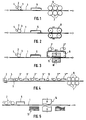
- FIG. 1 shows the support to be coated, which of course does not have to be a tape as shown schematically, but of course could also be a sequence of tracks, plates or the like.
- This carrier 1 is coated with the aid of a coating device 2, which comprises a transfer roller 3 and a dispersion application roller 4, directly with the aqueous dispersion layer, which is then predried in a drying device 5.
- This drying device can be, for example, a nozzle dryer or an IR section. After this predrying, the actual melt flow hardening follows, which is already the simple one shown in FIG. 1 Embodiment is equipped as an interval contact hardening with a plurality of heated contact rollers 6.
- FIG. 2 shows an embodiment in which, instead of a calender roller arrangement for curing the predried film, contact curing is carried out using a double belt machine 8.
- the coating of the carrier 1 takes place partly directly with the aid of the application device 2, partly indirectly with the aid of coating devices 2 'and 2' 'working on the belt 9 of the double belt machine.
- a modified contact hardening is also shown in this exemplary embodiment, which is illustrated schematically by the press with the jaws 10 and 11. These heated press jaws 10 and 11 also effect the transfer of the films of the coating devices 2 ′ and 2 ′′ onto the carrier 1 with the contact hardening.
- FIG. 4 schematically shows a device with a plurality of stations, such as, for example is suitable for the opaque pigmented coating of chipboard, hardboard or MDF. It comprises a plurality of application devices 2, 2 ', 2''and2''' and correspondingly a plurality of dryers 5, 5 ', 5''and5''' as well as a schematically arranged printing machine 12.
- the double-roll coating device 2 applies a dispersion layer to the flat plates arriving on the transfer web 1, which in turn is predried in a known manner in the dryer 5 at temperatures between 30 and 100 ° C.
- the plates are placed on an intermediate stack 13 and then processed into molded parts in a molding press 14, the melt flow hardening of the dispersion layer initially only predried on the surface of the flat plates being carried out with the pressing into the desired shape.
- other shaped bodies such as e.g. Manufacture party plates and cups from simple cardboard, because the coatings according to the invention - despite the use of aqueous emulsions as the starting material - are extremely waterproof after melt hardening.
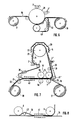
- FIG. 6 schematically shows one possibility of how a conventional calender can be converted for the transfer coating according to the invention.
- the layer applied to the hot calender roll 20 at the top with the aid of the coating devices 2, 2 ′ is transferred to the belt 16 to be coated in the transfer process, with cooling to improve the detachment of the layer adhering to the belt 16 from the calender.
- the cooling belt 40 which is cooled by the nozzle cooling device 41, so that it lies cold in the outlet area of the belt 16 from the calender roll 20 on the underside of this belt 16 and thus results in such a strong cooling that a much better separation effect between the transfer layer the band 16 and the calender surface is given.
- FIGS. 7 and 8 A preferred embodiment of an apparatus according to the invention for forming film coatings is shown in FIGS. 7 and 8.
- This is a transfer device in which the film is applied from a transfer belt 15 to the actual carrier belt 16 to be coated.
- This carrier tape 16 is only to be understood schematically, since it does not have to be a tape which is wound from a roll 17 onto a roll 18. Instead of this, a sequence of sheets could of course also be provided with a coating using the transfer coating device according to FIG. 7 instead of a band 16.
- the transfer coating device comprises the actual transfer station 19 with heated calendar rolls 6 and counter-pressure rolls 7 as well as cooled calender rolls 6a and counter-pressure rolls 7a as well as the drying device 5, which in addition to a controllably heatable deflection roll 20 within a hood 29 can also comprise radiation heating devices indicated schematically by arrows.
- the transfer belt 15, which can be a plastic or metal belt with an extremely smooth surface, runs between the transfer station 19 and the deflection roller 20.
- An aqueous dispersion according to the invention, which is predried in the dryer 5, is applied to this belt with the aid of an application device 2, which is again only indicated schematically, in a manner known per se, that is to say by knife coating, spraying or the like.
- a further layer for example an adhesion promoter layer, can be applied schematically indicated further application device 2 ', which can also comprise different stages.
- adhesion promoter layer can be applied schematically indicated further application device 2 ', which can also comprise different stages.
- These two layers i.e. the pre-dried film layer 21 and the adhesion promoter layer 22 - which are shown schematically in dashed lines in FIG.
- the cooling additionally favors the detachment of the film according to the invention from the transfer belt 15, the actual smooth, abrasion-resistant film 21 now being present as the top cover layer, which is particularly firmly connected to the carrier 16 by the adhesive layer 22 underneath.
- a nozzle cooling section 41 is also provided in FIG. 7, wherein this nozzle cooling section may also completely replace the cooling rolls 6a, 7a. In any case, it has been found useful, if not necessary, to provide cooling in such a transfer method after transfer to the belt to be coated, in order to achieve a much smoother, cleaner detachment from the transfer belt.
- a cutting and gluing device 30 indicated only schematically as a box, is provided, so that when the transfer belt 15 needs to be changed periodically, it can first be cut open, in order to glue a new transfer belt to the leading end, in order to then Pulling the tape through the device then finally connect the ends of the new tape section together.
- the cutting and gluing device 30 should be designed so that the tapes are cut obliquely at the joint, the bevel cut should be made so that it runs from top to bottom against the direction of travel, so that when coating material is applied to the transfer belt this cannot be pressed into the cut by the rollers and could possibly form beads. If the material is suitable, it is advisable in any case to provide as seamless a weld as possible instead of simply gluing the transfer belt.
- the lifting device indicated schematically at 31 enables a very simple adaptation to different belt speeds.
- the wrap must be correspondingly lower so that the temperature in the layers 21, 22 does not become too high.
- the lifting device 31 is adjustable, for example in the dashed position 31 ', in which there is only a very short contact distance with the calender roller 6 and thus also a correspondingly shorter period of time in spite of the low rotational speed is achieved, so that ultimately the desired actual heating of the layers 21, 22 can be controlled in this way at constant temperatures of the rollers 6.
- a detour of the transfer belt 15 between the calender rolls 6 is indicated in order to compensate for the effect of any shocks or surface defects of the transfer belt.
- the counter rolls have been omitted in this figure for the sake of simplicity - a nozzle cooling section 41 is again arranged in front of the lifting roll 42 in order to achieve this detour in order to in turn lift the transfer belt 15 from the belt 16 to be coated to achieve clean and smooth.
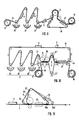
- FIG. 9 shows a schematic printing device in which a coating according to the invention is also applied to the printing layers at the same time.
- the paper or foil tape 16 unwound from the roll 17 is printed in the schematic printing stations 25 and 26, although more than two can of course also be provided, and then each dried with the aid of dryers 5.
- a dispersion according to the invention is then applied to the printed strip surface in the application station 27 and again predried in the third dryer 5. With the help of the heated calender roll 6, the predried dispersion film is melted into a film and then the paper web 16, which is printed in this way and at the same time is protected on the surface by a film according to the invention, is wound onto a roll 18.
- a cooling belt 40 with a nozzle cooling section 41 is also provided in the arrangement according to FIG. 9 in order to prevent that the smooth film layer formed by the wrapping of the heated calender 6 on the belt 16 must be torn hot off the calender surface.
- the heat of the calender 6 is practically not impaired by the cooling belt 40, so that the heat of the calender comes through this cooling belt in the same way as if the cooling belt were not present.
- the film layer formed is now between the belt 16 and the cooling belt 40, so that when leaving the calender surface this film layer is still between the two belts.
- the belts 40 and 16 are only separated after passing through the cooling section 41. At this stage, however, this is now possible without any problems, since the cooling section also cools down the layer formed by melt flow between the two belts to such an extent that the separation no longer causes problems.
- FIG. 10 finally shows a transfer printing device in which, in a commercially available web printing press comprising the various printing units 25, 26 and 28, instead of printing on the actual carrier, preferably a paper web, a transfer belt 15 made of metal or plastic is printed onto which first with the aid of an application device 2, an aqueous dispersion has been applied and predried in a dryer 5.
- the three printed layers indicated by the application units 25, 26 and 28 are thus printed on the predried dispersion layer which, after passing through the printing press D, enters a transfer device 19. In this the melting of the dispersion into a film takes place with simultaneous transfer of this film and that printed on it and after it Transfer of printing layers lying below it to the carrier 16.
- the transfer device 19 again contains two hot calender rolls 6 with corresponding counter-pressure rolls 7, in front of and behind which lifting rolls 31 and 31 'are arranged, which serve to change the wrap angle of the calender rolls 6 in accordance with the running speeds of the belts 15 and 16 in order in this way to be able to set the desired heating of the preheated dispersion layer and thus the exact temperature at which the film according to the invention is formed by melt flow hardening.
- the lifting rolls 31, 31 ' are in the respective dashed position so that also the dashed position of the transfer belt 16 results.
- the actual transfer station is in turn followed by a nozzle cooling section 41 in order to achieve a clean separation of the transfer belt and the coated belt 16 with the film adhering to it from the melt flow. This separation is further favored by the fact that the air blown into the nozzle cooling device 41 is also blown in between the separating belts at 44, thus making it even easier to lift them apart.
- the modified calendering device shown in FIG. 11 is special for existing calenders thought. After a direct coating of either the endless belt 1 or of individual sheets transported on the belt 1 with the aid of a coating device 2 according to FIGS. 1 to 3 and a predrying by a dryer 5, the belt 1 runs under a conventional calender 6 of an existing calendering machine which is in accordance with the invention is supplemented by an additional circumferential band 32 made of metal or plastic.
- this belt 32 enables the contact path to be adapted to the production speed, with a downstream nozzle cooling 34 after the melt flow hardening of the application layer on belt 1 or sheets transported on it ensure rapid cooling, so that extremely high production speeds are possible.
- Cutting and gluing devices are again indicated at 35 in order to be able to periodically change the tape 32.
- Such a cutting and gluing device is especially intended when using plastic tapes 32, while metal tapes, which also have a longer service life anyway, are to be replaced as a whole and prefabricated tape, but this usually causes difficulties in terms of machine technology (roller bearings on both sides).
- the invention is not restricted to the exemplary embodiments shown. It would also be conceivable, in particular with regard to the transfer process described above, that the dispersion according to the invention not only runs pre-dried into the web printing press, but has already been formed by melt contact hardening before it enters the web printing press, which film is then applied together with those Printing layers and an adhesive layer in the transfer station 19 of FIG. 10 is applied to the actual substrate 16 to be printed. In this case, the transfer station 19 is not used for film formation at the same time.
Landscapes
- Life Sciences & Earth Sciences (AREA)
- Engineering & Computer Science (AREA)
- Wood Science & Technology (AREA)
- Application Of Or Painting With Fluid Materials (AREA)
- Paints Or Removers (AREA)
- Non-Metallic Protective Coatings For Printed Circuits (AREA)
Priority Applications (1)
| Application Number | Priority Date | Filing Date | Title |
|---|---|---|---|
| AT89101246T ATE96700T1 (de) | 1988-01-30 | 1989-01-25 | Verfahren und vorrichtung zum herstellen schnellhaertender ueberzuege auf traegerkoerpern. |
Applications Claiming Priority (2)
| Application Number | Priority Date | Filing Date | Title |
|---|---|---|---|
| DE3802797 | 1988-01-30 | ||
| DE3802797A DE3802797A1 (de) | 1988-01-30 | 1988-01-30 | Verfahren und vorrichtung zum herstellen schnellhaertender ueberzuege auf traegerkoerpern |
Publications (3)
| Publication Number | Publication Date |
|---|---|
| EP0326919A2 EP0326919A2 (de) | 1989-08-09 |
| EP0326919A3 EP0326919A3 (en) | 1990-12-27 |
| EP0326919B1 true EP0326919B1 (de) | 1993-11-03 |
Family
ID=6346326
Family Applications (1)
| Application Number | Title | Priority Date | Filing Date |
|---|---|---|---|
| EP89101246A Expired - Lifetime EP0326919B1 (de) | 1988-01-30 | 1989-01-25 | Verfahren und Vorrichtung zum Herstellen schnellhärtender Überzüge auf Trägerkörpern |
Country Status (4)
| Country | Link |
|---|---|
| EP (1) | EP0326919B1 (enExample) |
| AT (1) | ATE96700T1 (enExample) |
| DE (2) | DE3802797A1 (enExample) |
| ES (1) | ES2045203T3 (enExample) |
Cited By (1)
| Publication number | Priority date | Publication date | Assignee | Title |
|---|---|---|---|---|
| WO2023136786A1 (en) | 2022-01-17 | 2023-07-20 | Prntsys Maki̇na Ve Ambalaj Sanayi̇ Ti̇caret Li̇mi̇ted Şi̇rketi̇ | Lacquer coating system and method |
Families Citing this family (28)
| Publication number | Priority date | Publication date | Assignee | Title |
|---|---|---|---|---|
| DE4006376A1 (de) * | 1990-03-01 | 1991-09-05 | Buffalo Gmbh | Verfahren zur herstellung von schildern und insbesondere hierfuer geeigneter dispersionslack |
| DE4118249C2 (de) * | 1991-06-04 | 1994-10-27 | Guenther Dr Schwarz | Verfahren und Vorrichtung zur Massenkonservierung von Archivalien |
| FR2684025B1 (fr) * | 1991-11-22 | 1993-12-31 | Merlin Gerin | Installation d'application de peinture en couche epaisse. |
| DE4311235A1 (de) * | 1992-04-24 | 1993-10-28 | Erich Killar | Verfahren zum Beschichten oder Bedrucken einer Kunststoff-Folie mit wässerigen Beschichtungsmedien, lösungsmittelhaltigen Beschichtungsmedien oder Mischungen davon, UV-härtbaren Lacken oder Farben, sowie PVC-Pasten |
| DE4239163C1 (de) * | 1992-11-21 | 1994-05-26 | Billhofer Maschf Gmbh | Verfahren und Vorrichtung zum Herstellen schnellhärtender Überzüge |
| DE4305081C2 (de) | 1993-02-19 | 1996-08-01 | Minnesota Mining & Mfg | Verfahren und Vorrichtung zum Auftragen von Haftkleber auf Bogen aus Papier oder dergleichen Material |
| DE4417784A1 (de) * | 1994-05-20 | 1995-11-23 | Dlw Ag | Verfahren und Vorrichtung zum Bemustern von Bahnen oder Bogen sowie damit hergestellte Bahnen bzw. Bogen |
| JPH10504239A (ja) * | 1994-08-17 | 1998-04-28 | ミネソタ・マイニング・アンド・マニュファクチュアリング・カンパニー | シートに塗布材料を塗布する方法及び装置 |
| US5958135A (en) | 1994-08-17 | 1999-09-28 | Minnesota Mining And Manufacturing Company | Apparatus and method for applying coating materials to individual sheet members |
| DE19543099C2 (de) * | 1995-11-18 | 1998-02-19 | Huettenhoelscher Maschinenbau | Verfahren und Vorrichtung zum Übertragen eines Druckbildes von einer Trägerbahn auf ein Substrat |
| FR2767074B1 (fr) * | 1997-08-08 | 1999-10-22 | Lorraine Laminage | Procede et dispositif de revetement en continu d'au moins une bande metallique par un film en polymere reticulable fluide |
| TW418116B (en) * | 1997-11-04 | 2001-01-11 | Matsushita Electric Industrial Co Ltd | Water-repellent coating and coating device |
| US6165308A (en) * | 1998-11-06 | 2000-12-26 | Lilly Industries, Inc. | In-press process for coating composite substrates |
| DE19933100A1 (de) * | 1999-07-15 | 2001-01-18 | Hymmen Theodor Gmbh | Verfahren und Vorrichtung zum Beschichten von Werkstücken mit Pulverlacken |
| ES2190828B2 (es) * | 2000-02-02 | 2004-08-01 | Euroinstalaciones Caballero S.L. | Metodo de fabricar perfiles pintados a partir de bandas metalicas y maquina correspondiente. |
| NL1015260C2 (nl) * | 2000-05-22 | 2001-11-26 | Corus Staal Bv | Werkwijze en inrichting voor het bekleden van een voortbewegende metalen productband. |
| DE10064171B4 (de) * | 2000-12-22 | 2004-05-27 | Felix Schoeller Jr. Foto- Und Spezialpapiere Gmbh & Co. Kg | Schichtträger für Bildaufzeichnungsmaterialien |
| WO2008061765A1 (de) * | 2006-11-23 | 2008-05-29 | S.D. Warren Company, D/B/A | Verfahren zum direktbedrucken von holzwerkstoffplatten |
| CN105499062B (zh) * | 2005-11-24 | 2017-08-15 | 克诺普拉斯技术股份公司 | 用流动性涂层材料为光滑的或具有构造结构的表面涂层的涂层设备 |
| CN101484247A (zh) * | 2005-11-24 | 2009-07-15 | 克诺普拉斯技术股份公司 | 用流动性涂层材料为光滑的或具有构造结构的表面涂层的涂层设备 |
| CA2639695C (en) | 2007-09-19 | 2015-07-07 | Prolam, Societe En Commandite | Hardwood truck flooring with wood preservative |
| US9682493B2 (en) | 2008-05-09 | 2017-06-20 | Prolam, Societe En Commandite | Method for impregnation of wood component with solid paraffin wax, apparatus therefor and wood component so impregnated |
| RU2418116C1 (ru) * | 2009-12-14 | 2011-05-10 | Федеральное государственное унитарное предприятие "Обнинское научно-производственное предприятие "Технология" | Устройство для пропитки волокнистого материала связующим |
| US8241938B2 (en) | 2010-07-02 | 2012-08-14 | Primestar Solar, Inc. | Methods of forming a conductive transparent oxide film layer for use in a cadmium telluride based thin film photovoltaic device |
| US8236601B2 (en) * | 2010-07-02 | 2012-08-07 | Primestar Solar, Inc. | Apparatus and methods of forming a conductive transparent oxide film layer for use in a cadmium telluride based thin film photovoltaic device |
| US8673777B2 (en) * | 2011-09-30 | 2014-03-18 | First Solar, Inc. | In-line deposition system and process for deposition of a thin film layer |
| EP2946919A1 (de) * | 2014-05-19 | 2015-11-25 | Basf Se | Mehrschichtige lignocellulosewerkstoffe mit innenliegender dampfsperre |
| CN115228704B (zh) * | 2022-07-28 | 2023-06-06 | 广州通泽机械有限公司 | 一种以不同方式涂布且涂布量联动控制的复合方法及设备 |
Citations (1)
| Publication number | Priority date | Publication date | Assignee | Title |
|---|---|---|---|---|
| EP0062245A1 (de) * | 1981-03-31 | 1982-10-13 | BASF Lacke + Farben AG | Wässrige Dispersion oder Emulsion filmbildender Bindemittel |
Family Cites Families (5)
| Publication number | Priority date | Publication date | Assignee | Title |
|---|---|---|---|---|
| DE2802184C3 (de) * | 1978-01-19 | 1981-09-10 | Agfa-Gevaert Ag, 5090 Leverkusen | Verfahren zur versuchsweisen Beschichtung von Papier- oder Folienbahnschlaufen mit viskosen Flüssigkeiten |
| FI792052A7 (fi) * | 1979-06-28 | 1981-01-01 | Ruusunen M | Menetelmä ja laite rainamateriaalin päällystämiseksi kuumasulateliimalla. |
| EP0171482B1 (de) * | 1984-08-17 | 1988-05-18 | Werner Bandi | Verfahren zur Herstellung einer Beschichtung auf ein Trägermaterial |
| DE3545618A1 (de) * | 1985-12-21 | 1987-06-25 | Basf Lacke & Farben | Wasserverduennbares ueberzugsmittel zur herstellung der basisschicht eines mehrschichtueberzuges |
| DE3610732C2 (de) * | 1986-03-29 | 1995-05-18 | Basf Lacke & Farben | Verfahren zur einschichtigen Beschichtung von Finish-Folien und Endloskanten |
-
1988
- 1988-01-30 DE DE3802797A patent/DE3802797A1/de active Granted
-
1989
- 1989-01-25 DE DE89101246T patent/DE58906060D1/de not_active Expired - Fee Related
- 1989-01-25 EP EP89101246A patent/EP0326919B1/de not_active Expired - Lifetime
- 1989-01-25 ES ES89101246T patent/ES2045203T3/es not_active Expired - Lifetime
- 1989-01-25 AT AT89101246T patent/ATE96700T1/de not_active IP Right Cessation
Patent Citations (1)
| Publication number | Priority date | Publication date | Assignee | Title |
|---|---|---|---|---|
| EP0062245A1 (de) * | 1981-03-31 | 1982-10-13 | BASF Lacke + Farben AG | Wässrige Dispersion oder Emulsion filmbildender Bindemittel |
Cited By (2)
| Publication number | Priority date | Publication date | Assignee | Title |
|---|---|---|---|---|
| WO2023136786A1 (en) | 2022-01-17 | 2023-07-20 | Prntsys Maki̇na Ve Ambalaj Sanayi̇ Ti̇caret Li̇mi̇ted Şi̇rketi̇ | Lacquer coating system and method |
| EP4444545A4 (en) * | 2022-01-17 | 2025-01-01 | Dev Sanayi Teknolojileri Anonim Sirketi | SYSTEM AND METHOD FOR APPLYING A LACQUER COATING |
Also Published As
| Publication number | Publication date |
|---|---|
| DE3802797A1 (de) | 1989-08-10 |
| EP0326919A2 (de) | 1989-08-09 |
| ATE96700T1 (de) | 1993-11-15 |
| ES2045203T3 (es) | 1994-01-16 |
| EP0326919A3 (en) | 1990-12-27 |
| DE58906060D1 (de) | 1993-12-09 |
| DE3802797C2 (enExample) | 1990-03-08 |
Similar Documents
| Publication | Publication Date | Title |
|---|---|---|
| EP0326919B1 (de) | Verfahren und Vorrichtung zum Herstellen schnellhärtender Überzüge auf Trägerkörpern | |
| DE60005077T2 (de) | Laminat und dessen Herstellung | |
| DE68910548T2 (de) | Verfahren zur Herstellung eines dekorativen härtbaren Schichtstoffes. | |
| DE60003097T2 (de) | Verfahren zum beiderseitigen Behandeln eines Blattes | |
| EP2992142B1 (de) | Verfahren zur herstellung einer bedruckbaren ein- oder mehrschichtigen materialbahn sowie eine zugehörige anlage zur herstellung einer derartigen materialbahn | |
| EP1691991B1 (de) | Dekorlaminat und dekorlaminatplatte und verfahren zum herstellen beider | |
| DE2727312B2 (enExample) | ||
| DE69523788T2 (de) | Verfahren zum Aufbringen einer Beschichtung auf Bögen | |
| DE69534794T2 (de) | Verfahren und Vorrichtung zum Aufbringen einer Beschichtung auf Bögen | |
| DE1696153A1 (de) | Verfahren und Vorrichtung zum UEberziehen oder Bestreichen von Papier oder Bogenmaterial mit Aussen- oder Oberflaechenschicht | |
| DE4336214A1 (de) | Verfahren und Vorrichtung zur Herstellung von Überzügen auf Oberflächen | |
| AT248858B (de) | Verfahren und Vorrichtung zur kontinuierlichen Herstellung von einzelnen Kartonzuschnitten mit einem glatten, glänzenden Überzug | |
| EP0542966B1 (de) | Verfahren und vorrichtung zur massenkonservierung von archivalien | |
| EP0930161B1 (de) | Verfahren und Vorrichtung zur Beschichtung eines Druckerzeugnisses | |
| DE69510109T2 (de) | Verfahren zur Herstellung von Gleitschutzpappe | |
| DE10352865B4 (de) | Verfahren und Vorrichtung zur Beschichtung von flächenförmigen Substraten wie Papier | |
| DE3438489A1 (de) | Verfahren zur oberflaechenkaschierung selbsttragender formteile, beispielsweise fuer die innenverkleidung von kraftfahrzeugen, und vorrichtung zur durchfuehrung des verfahrens | |
| DE4008044C2 (enExample) | ||
| EP0699530B1 (de) | Verfahren und Vorrichtung zum Trocknen von im Offsetverfahren bedruckten Kunststoff-Folienbahnen | |
| EP0050269B1 (de) | Verfahren und Vorrichtung zum Rundumlackieren von zylindrischen Hohlkörpern, wie Dosenrümpfe | |
| DE3914780C2 (de) | Einrichtung zur kontinuierlichen Herstellung einer endlosen, dünnen Spanplattenbahn sowie Verfahren zum Lackieren einer mit einer Papierbeschichtung versehenen Oberfläche dünner Spanplatten | |
| DE2022562A1 (de) | Kontinuierliches Verfahren zur Herstellung dekorativer Platten und Vorrichtung zur Durchfuehrung des Verfahrens | |
| DE1571910C3 (de) | Druckempfindliches Farbübertragungsblatt, -band od.dgl. und Verfahren zu seiner Herstellung | |
| DE69316619T2 (de) | Maschine zum staubfreien Überziehen von Papier oder Karton mit einem transparenten Film mit Hilfe von lösungsmittelfreien Klebstoffen | |
| AT46111B (de) | Verfahren zum Satinieren von Papier, Karton und dergl. |
Legal Events
| Date | Code | Title | Description |
|---|---|---|---|
| PUAI | Public reference made under article 153(3) epc to a published international application that has entered the european phase |
Free format text: ORIGINAL CODE: 0009012 |
|
| AK | Designated contracting states |
Kind code of ref document: A2 Designated state(s): AT BE CH DE ES FR GB GR IT LI LU NL SE |
|
| PUAL | Search report despatched |
Free format text: ORIGINAL CODE: 0009013 |
|
| AK | Designated contracting states |
Kind code of ref document: A3 Designated state(s): AT BE CH DE ES FR GB GR IT LI LU NL SE |
|
| 17P | Request for examination filed |
Effective date: 19910121 |
|
| 17Q | First examination report despatched |
Effective date: 19911209 |
|
| GRAA | (expected) grant |
Free format text: ORIGINAL CODE: 0009210 |
|
| AK | Designated contracting states |
Kind code of ref document: B1 Designated state(s): AT BE CH DE ES FR GB GR IT LI LU NL SE |
|
| REF | Corresponds to: |
Ref document number: 96700 Country of ref document: AT Date of ref document: 19931115 Kind code of ref document: T |
|
| REF | Corresponds to: |
Ref document number: 58906060 Country of ref document: DE Date of ref document: 19931209 |
|
| ITF | It: translation for a ep patent filed | ||
| ET | Fr: translation filed | ||
| REG | Reference to a national code |
Ref country code: ES Ref legal event code: FG2A Ref document number: 2045203 Country of ref document: ES Kind code of ref document: T3 |
|
| EPTA | Lu: last paid annual fee | ||
| GBT | Gb: translation of ep patent filed (gb section 77(6)(a)/1977) |
Effective date: 19940120 |
|
| REG | Reference to a national code |
Ref country code: GR Ref legal event code: FG4A Free format text: 3010153 |
|
| PLBE | No opposition filed within time limit |
Free format text: ORIGINAL CODE: 0009261 |
|
| STAA | Information on the status of an ep patent application or granted ep patent |
Free format text: STATUS: NO OPPOSITION FILED WITHIN TIME LIMIT |
|
| 26N | No opposition filed | ||
| EAL | Se: european patent in force in sweden |
Ref document number: 89101246.0 |
|
| PGFP | Annual fee paid to national office [announced via postgrant information from national office to epo] |
Ref country code: GB Payment date: 19980115 Year of fee payment: 10 |
|
| PGFP | Annual fee paid to national office [announced via postgrant information from national office to epo] |
Ref country code: FR Payment date: 19980116 Year of fee payment: 10 |
|
| PGFP | Annual fee paid to national office [announced via postgrant information from national office to epo] |
Ref country code: GR Payment date: 19980128 Year of fee payment: 10 |
|
| PGFP | Annual fee paid to national office [announced via postgrant information from national office to epo] |
Ref country code: ES Payment date: 19980129 Year of fee payment: 10 |
|
| PGFP | Annual fee paid to national office [announced via postgrant information from national office to epo] |
Ref country code: SE Payment date: 19980130 Year of fee payment: 10 Ref country code: CH Payment date: 19980130 Year of fee payment: 10 Ref country code: AT Payment date: 19980130 Year of fee payment: 10 |
|
| PGFP | Annual fee paid to national office [announced via postgrant information from national office to epo] |
Ref country code: NL Payment date: 19980202 Year of fee payment: 10 |
|
| PGFP | Annual fee paid to national office [announced via postgrant information from national office to epo] |
Ref country code: LU Payment date: 19980216 Year of fee payment: 10 |
|
| PGFP | Annual fee paid to national office [announced via postgrant information from national office to epo] |
Ref country code: BE Payment date: 19980217 Year of fee payment: 10 |
|
| PG25 | Lapsed in a contracting state [announced via postgrant information from national office to epo] |
Ref country code: LU Free format text: LAPSE BECAUSE OF NON-PAYMENT OF DUE FEES Effective date: 19990125 Ref country code: GB Free format text: LAPSE BECAUSE OF NON-PAYMENT OF DUE FEES Effective date: 19990125 Ref country code: AT Free format text: LAPSE BECAUSE OF NON-PAYMENT OF DUE FEES Effective date: 19990125 |
|
| PG25 | Lapsed in a contracting state [announced via postgrant information from national office to epo] |
Ref country code: SE Free format text: LAPSE BECAUSE OF NON-PAYMENT OF DUE FEES Effective date: 19990126 Ref country code: ES Free format text: LAPSE BECAUSE OF THE APPLICANT RENOUNCES Effective date: 19990126 |
|
| PG25 | Lapsed in a contracting state [announced via postgrant information from national office to epo] |
Ref country code: LI Free format text: LAPSE BECAUSE OF NON-PAYMENT OF DUE FEES Effective date: 19990131 Ref country code: GR Free format text: LAPSE BECAUSE OF NON-PAYMENT OF DUE FEES Effective date: 19990131 Ref country code: CH Free format text: LAPSE BECAUSE OF NON-PAYMENT OF DUE FEES Effective date: 19990131 Ref country code: BE Free format text: LAPSE BECAUSE OF NON-PAYMENT OF DUE FEES Effective date: 19990131 |
|
| BERE | Be: lapsed |
Owner name: SCHWARZ GUNTHER Effective date: 19990131 |
|
| PG25 | Lapsed in a contracting state [announced via postgrant information from national office to epo] |
Ref country code: NL Free format text: LAPSE BECAUSE OF NON-PAYMENT OF DUE FEES Effective date: 19990801 |
|
| GBPC | Gb: european patent ceased through non-payment of renewal fee |
Effective date: 19990125 |
|
| REG | Reference to a national code |
Ref country code: CH Ref legal event code: PL |
|
| PG25 | Lapsed in a contracting state [announced via postgrant information from national office to epo] |
Ref country code: FR Free format text: LAPSE BECAUSE OF NON-PAYMENT OF DUE FEES Effective date: 19990930 |
|
| REG | Reference to a national code |
Ref country code: FR Ref legal event code: ST |
|
| PGFP | Annual fee paid to national office [announced via postgrant information from national office to epo] |
Ref country code: DE Payment date: 20010102 Year of fee payment: 13 |
|
| REG | Reference to a national code |
Ref country code: ES Ref legal event code: FD2A Effective date: 20010402 |
|
| PG25 | Lapsed in a contracting state [announced via postgrant information from national office to epo] |
Ref country code: DE Free format text: LAPSE BECAUSE OF NON-PAYMENT OF DUE FEES Effective date: 20020801 |
|
| PG25 | Lapsed in a contracting state [announced via postgrant information from national office to epo] |
Ref country code: IT Free format text: LAPSE BECAUSE OF NON-PAYMENT OF DUE FEES;WARNING: LAPSES OF ITALIAN PATENTS WITH EFFECTIVE DATE BEFORE 2007 MAY HAVE OCCURRED AT ANY TIME BEFORE 2007. THE CORRECT EFFECTIVE DATE MAY BE DIFFERENT FROM THE ONE RECORDED. Effective date: 20050125 |