EP0326150A1 - Système de commande sensible à la charge pour un circuit hydraulique - Google Patents
Système de commande sensible à la charge pour un circuit hydraulique Download PDFInfo
- Publication number
- EP0326150A1 EP0326150A1 EP89101426A EP89101426A EP0326150A1 EP 0326150 A1 EP0326150 A1 EP 0326150A1 EP 89101426 A EP89101426 A EP 89101426A EP 89101426 A EP89101426 A EP 89101426A EP 0326150 A1 EP0326150 A1 EP 0326150A1
- Authority
- EP
- European Patent Office
- Prior art keywords
- delivery amount
- pressure
- pump
- target delivery
- target
- Prior art date
- Legal status (The legal status is an assumption and is not a legal conclusion. Google has not performed a legal analysis and makes no representation as to the accuracy of the status listed.)
- Granted
Links
- 230000000670 limiting effect Effects 0.000 claims abstract description 155
- 239000012530 fluid Substances 0.000 claims abstract description 27
- 238000001514 detection method Methods 0.000 claims abstract description 26
- 230000004044 response Effects 0.000 claims abstract description 12
- 238000004364 calculation method Methods 0.000 claims description 24
- 230000001276 controlling effect Effects 0.000 claims description 18
- 230000006870 function Effects 0.000 description 40
- 238000000034 method Methods 0.000 description 29
- 238000006073 displacement reaction Methods 0.000 description 26
- 208000036366 Sensation of pressure Diseases 0.000 description 25
- 238000010586 diagram Methods 0.000 description 17
- 229920006395 saturated elastomer Polymers 0.000 description 10
- 230000008569 process Effects 0.000 description 8
- 230000007246 mechanism Effects 0.000 description 7
- XEEYBQQBJWHFJM-UHFFFAOYSA-N Iron Chemical group [Fe] XEEYBQQBJWHFJM-UHFFFAOYSA-N 0.000 description 6
- 238000007792 addition Methods 0.000 description 6
- 230000009467 reduction Effects 0.000 description 6
- 239000000446 fuel Substances 0.000 description 5
- 238000002347 injection Methods 0.000 description 4
- 239000007924 injection Substances 0.000 description 4
- 239000000543 intermediate Substances 0.000 description 4
- 239000000126 substance Substances 0.000 description 4
- 230000007423 decrease Effects 0.000 description 3
- 230000010354 integration Effects 0.000 description 3
- 230000007704 transition Effects 0.000 description 3
- 238000002485 combustion reaction Methods 0.000 description 2
- 238000010276 construction Methods 0.000 description 2
- 230000007812 deficiency Effects 0.000 description 2
- 230000001419 dependent effect Effects 0.000 description 2
- 238000006467 substitution reaction Methods 0.000 description 2
- 230000009471 action Effects 0.000 description 1
- 230000008901 benefit Effects 0.000 description 1
- 230000003247 decreasing effect Effects 0.000 description 1
- 230000001771 impaired effect Effects 0.000 description 1
- 230000007935 neutral effect Effects 0.000 description 1
- 229920000136 polysorbate Polymers 0.000 description 1
- 230000001105 regulatory effect Effects 0.000 description 1
- 230000002311 subsequent effect Effects 0.000 description 1
- 230000001052 transient effect Effects 0.000 description 1
Images


Classifications
-
- E—FIXED CONSTRUCTIONS
- E02—HYDRAULIC ENGINEERING; FOUNDATIONS; SOIL SHIFTING
- E02F—DREDGING; SOIL-SHIFTING
- E02F9/00—Component parts of dredgers or soil-shifting machines, not restricted to one of the kinds covered by groups E02F3/00 - E02F7/00
- E02F9/20—Drives; Control devices
- E02F9/2025—Particular purposes of control systems not otherwise provided for
-
- F—MECHANICAL ENGINEERING; LIGHTING; HEATING; WEAPONS; BLASTING
- F15—FLUID-PRESSURE ACTUATORS; HYDRAULICS OR PNEUMATICS IN GENERAL
- F15B—SYSTEMS ACTING BY MEANS OF FLUIDS IN GENERAL; FLUID-PRESSURE ACTUATORS, e.g. SERVOMOTORS; DETAILS OF FLUID-PRESSURE SYSTEMS, NOT OTHERWISE PROVIDED FOR
- F15B9/00—Servomotors with follow-up action, e.g. obtained by feed-back control, i.e. in which the position of the actuated member conforms with that of the controlling member
- F15B9/02—Servomotors with follow-up action, e.g. obtained by feed-back control, i.e. in which the position of the actuated member conforms with that of the controlling member with servomotors of the reciprocatable or oscillatable type
- F15B9/08—Servomotors with follow-up action, e.g. obtained by feed-back control, i.e. in which the position of the actuated member conforms with that of the controlling member with servomotors of the reciprocatable or oscillatable type controlled by valves affecting the fluid feed or the fluid outlet of the servomotor
- F15B9/10—Servomotors with follow-up action, e.g. obtained by feed-back control, i.e. in which the position of the actuated member conforms with that of the controlling member with servomotors of the reciprocatable or oscillatable type controlled by valves affecting the fluid feed or the fluid outlet of the servomotor in which the controlling element and the servomotor each controls a separate member, these members influencing different fluid passages or the same passage
-
- E—FIXED CONSTRUCTIONS
- E02—HYDRAULIC ENGINEERING; FOUNDATIONS; SOIL SHIFTING
- E02F—DREDGING; SOIL-SHIFTING
- E02F9/00—Component parts of dredgers or soil-shifting machines, not restricted to one of the kinds covered by groups E02F3/00 - E02F7/00
- E02F9/20—Drives; Control devices
- E02F9/22—Hydraulic or pneumatic drives
- E02F9/2221—Control of flow rate; Load sensing arrangements
- E02F9/2225—Control of flow rate; Load sensing arrangements using pressure-compensating valves
- E02F9/2228—Control of flow rate; Load sensing arrangements using pressure-compensating valves including an electronic controller
-
- E—FIXED CONSTRUCTIONS
- E02—HYDRAULIC ENGINEERING; FOUNDATIONS; SOIL SHIFTING
- E02F—DREDGING; SOIL-SHIFTING
- E02F9/00—Component parts of dredgers or soil-shifting machines, not restricted to one of the kinds covered by groups E02F3/00 - E02F7/00
- E02F9/20—Drives; Control devices
- E02F9/22—Hydraulic or pneumatic drives
- E02F9/2221—Control of flow rate; Load sensing arrangements
- E02F9/2232—Control of flow rate; Load sensing arrangements using one or more variable displacement pumps
- E02F9/2235—Control of flow rate; Load sensing arrangements using one or more variable displacement pumps including an electronic controller
-
- E—FIXED CONSTRUCTIONS
- E02—HYDRAULIC ENGINEERING; FOUNDATIONS; SOIL SHIFTING
- E02F—DREDGING; SOIL-SHIFTING
- E02F9/00—Component parts of dredgers or soil-shifting machines, not restricted to one of the kinds covered by groups E02F3/00 - E02F7/00
- E02F9/20—Drives; Control devices
- E02F9/22—Hydraulic or pneumatic drives
- E02F9/2246—Control of prime movers, e.g. depending on the hydraulic load of work tools
-
- E—FIXED CONSTRUCTIONS
- E02—HYDRAULIC ENGINEERING; FOUNDATIONS; SOIL SHIFTING
- E02F—DREDGING; SOIL-SHIFTING
- E02F9/00—Component parts of dredgers or soil-shifting machines, not restricted to one of the kinds covered by groups E02F3/00 - E02F7/00
- E02F9/20—Drives; Control devices
- E02F9/22—Hydraulic or pneumatic drives
- E02F9/2278—Hydraulic circuits
- E02F9/2292—Systems with two or more pumps
-
- E—FIXED CONSTRUCTIONS
- E02—HYDRAULIC ENGINEERING; FOUNDATIONS; SOIL SHIFTING
- E02F—DREDGING; SOIL-SHIFTING
- E02F9/00—Component parts of dredgers or soil-shifting machines, not restricted to one of the kinds covered by groups E02F3/00 - E02F7/00
- E02F9/20—Drives; Control devices
- E02F9/22—Hydraulic or pneumatic drives
- E02F9/2278—Hydraulic circuits
- E02F9/2296—Systems with a variable displacement pump
-
- F—MECHANICAL ENGINEERING; LIGHTING; HEATING; WEAPONS; BLASTING
- F02—COMBUSTION ENGINES; HOT-GAS OR COMBUSTION-PRODUCT ENGINE PLANTS
- F02D—CONTROLLING COMBUSTION ENGINES
- F02D29/00—Controlling engines, such controlling being peculiar to the devices driven thereby, the devices being other than parts or accessories essential to engine operation, e.g. controlling of engines by signals external thereto
- F02D29/04—Controlling engines, such controlling being peculiar to the devices driven thereby, the devices being other than parts or accessories essential to engine operation, e.g. controlling of engines by signals external thereto peculiar to engines driving pumps
-
- F—MECHANICAL ENGINEERING; LIGHTING; HEATING; WEAPONS; BLASTING
- F15—FLUID-PRESSURE ACTUATORS; HYDRAULICS OR PNEUMATICS IN GENERAL
- F15B—SYSTEMS ACTING BY MEANS OF FLUIDS IN GENERAL; FLUID-PRESSURE ACTUATORS, e.g. SERVOMOTORS; DETAILS OF FLUID-PRESSURE SYSTEMS, NOT OTHERWISE PROVIDED FOR
- F15B11/00—Servomotor systems without provision for follow-up action; Circuits therefor
- F15B11/16—Servomotor systems without provision for follow-up action; Circuits therefor with two or more servomotors
- F15B11/161—Servomotor systems without provision for follow-up action; Circuits therefor with two or more servomotors with sensing of servomotor demand or load
- F15B11/165—Servomotor systems without provision for follow-up action; Circuits therefor with two or more servomotors with sensing of servomotor demand or load for adjusting the pump output or bypass in response to demand
-
- F—MECHANICAL ENGINEERING; LIGHTING; HEATING; WEAPONS; BLASTING
- F15—FLUID-PRESSURE ACTUATORS; HYDRAULICS OR PNEUMATICS IN GENERAL
- F15B—SYSTEMS ACTING BY MEANS OF FLUIDS IN GENERAL; FLUID-PRESSURE ACTUATORS, e.g. SERVOMOTORS; DETAILS OF FLUID-PRESSURE SYSTEMS, NOT OTHERWISE PROVIDED FOR
- F15B21/00—Common features of fluid actuator systems; Fluid-pressure actuator systems or details thereof, not covered by any other group of this subclass
- F15B21/08—Servomotor systems incorporating electrically operated control means
- F15B21/087—Control strategy, e.g. with block diagram
-
- F—MECHANICAL ENGINEERING; LIGHTING; HEATING; WEAPONS; BLASTING
- F15—FLUID-PRESSURE ACTUATORS; HYDRAULICS OR PNEUMATICS IN GENERAL
- F15B—SYSTEMS ACTING BY MEANS OF FLUIDS IN GENERAL; FLUID-PRESSURE ACTUATORS, e.g. SERVOMOTORS; DETAILS OF FLUID-PRESSURE SYSTEMS, NOT OTHERWISE PROVIDED FOR
- F15B2211/00—Circuits for servomotor systems
- F15B2211/20—Fluid pressure source, e.g. accumulator or variable axial piston pump
- F15B2211/205—Systems with pumps
- F15B2211/2053—Type of pump
- F15B2211/20546—Type of pump variable capacity
- F15B2211/20553—Type of pump variable capacity with pilot circuit, e.g. for controlling a swash plate
-
- F—MECHANICAL ENGINEERING; LIGHTING; HEATING; WEAPONS; BLASTING
- F15—FLUID-PRESSURE ACTUATORS; HYDRAULICS OR PNEUMATICS IN GENERAL
- F15B—SYSTEMS ACTING BY MEANS OF FLUIDS IN GENERAL; FLUID-PRESSURE ACTUATORS, e.g. SERVOMOTORS; DETAILS OF FLUID-PRESSURE SYSTEMS, NOT OTHERWISE PROVIDED FOR
- F15B2211/00—Circuits for servomotor systems
- F15B2211/20—Fluid pressure source, e.g. accumulator or variable axial piston pump
- F15B2211/255—Flow control functions
-
- F—MECHANICAL ENGINEERING; LIGHTING; HEATING; WEAPONS; BLASTING
- F15—FLUID-PRESSURE ACTUATORS; HYDRAULICS OR PNEUMATICS IN GENERAL
- F15B—SYSTEMS ACTING BY MEANS OF FLUIDS IN GENERAL; FLUID-PRESSURE ACTUATORS, e.g. SERVOMOTORS; DETAILS OF FLUID-PRESSURE SYSTEMS, NOT OTHERWISE PROVIDED FOR
- F15B2211/00—Circuits for servomotor systems
- F15B2211/30—Directional control
- F15B2211/305—Directional control characterised by the type of valves
- F15B2211/30505—Non-return valves, i.e. check valves
-
- F—MECHANICAL ENGINEERING; LIGHTING; HEATING; WEAPONS; BLASTING
- F15—FLUID-PRESSURE ACTUATORS; HYDRAULICS OR PNEUMATICS IN GENERAL
- F15B—SYSTEMS ACTING BY MEANS OF FLUIDS IN GENERAL; FLUID-PRESSURE ACTUATORS, e.g. SERVOMOTORS; DETAILS OF FLUID-PRESSURE SYSTEMS, NOT OTHERWISE PROVIDED FOR
- F15B2211/00—Circuits for servomotor systems
- F15B2211/30—Directional control
- F15B2211/305—Directional control characterised by the type of valves
- F15B2211/30525—Directional control valves, e.g. 4/3-directional control valve
- F15B2211/3053—In combination with a pressure compensating valve
- F15B2211/30535—In combination with a pressure compensating valve the pressure compensating valve is arranged between pressure source and directional control valve
-
- F—MECHANICAL ENGINEERING; LIGHTING; HEATING; WEAPONS; BLASTING
- F15—FLUID-PRESSURE ACTUATORS; HYDRAULICS OR PNEUMATICS IN GENERAL
- F15B—SYSTEMS ACTING BY MEANS OF FLUIDS IN GENERAL; FLUID-PRESSURE ACTUATORS, e.g. SERVOMOTORS; DETAILS OF FLUID-PRESSURE SYSTEMS, NOT OTHERWISE PROVIDED FOR
- F15B2211/00—Circuits for servomotor systems
- F15B2211/30—Directional control
- F15B2211/31—Directional control characterised by the positions of the valve element
- F15B2211/3105—Neutral or centre positions
- F15B2211/3111—Neutral or centre positions the pump port being closed in the centre position, e.g. so-called closed centre
-
- F—MECHANICAL ENGINEERING; LIGHTING; HEATING; WEAPONS; BLASTING
- F15—FLUID-PRESSURE ACTUATORS; HYDRAULICS OR PNEUMATICS IN GENERAL
- F15B—SYSTEMS ACTING BY MEANS OF FLUIDS IN GENERAL; FLUID-PRESSURE ACTUATORS, e.g. SERVOMOTORS; DETAILS OF FLUID-PRESSURE SYSTEMS, NOT OTHERWISE PROVIDED FOR
- F15B2211/00—Circuits for servomotor systems
- F15B2211/30—Directional control
- F15B2211/315—Directional control characterised by the connections of the valve or valves in the circuit
- F15B2211/3157—Directional control characterised by the connections of the valve or valves in the circuit being connected to a pressure source, an output member and a return line
- F15B2211/31576—Directional control characterised by the connections of the valve or valves in the circuit being connected to a pressure source, an output member and a return line having a single pressure source and a single output member
-
- F—MECHANICAL ENGINEERING; LIGHTING; HEATING; WEAPONS; BLASTING
- F15—FLUID-PRESSURE ACTUATORS; HYDRAULICS OR PNEUMATICS IN GENERAL
- F15B—SYSTEMS ACTING BY MEANS OF FLUIDS IN GENERAL; FLUID-PRESSURE ACTUATORS, e.g. SERVOMOTORS; DETAILS OF FLUID-PRESSURE SYSTEMS, NOT OTHERWISE PROVIDED FOR
- F15B2211/00—Circuits for servomotor systems
- F15B2211/30—Directional control
- F15B2211/32—Directional control characterised by the type of actuation
- F15B2211/329—Directional control characterised by the type of actuation actuated by fluid pressure
-
- F—MECHANICAL ENGINEERING; LIGHTING; HEATING; WEAPONS; BLASTING
- F15—FLUID-PRESSURE ACTUATORS; HYDRAULICS OR PNEUMATICS IN GENERAL
- F15B—SYSTEMS ACTING BY MEANS OF FLUIDS IN GENERAL; FLUID-PRESSURE ACTUATORS, e.g. SERVOMOTORS; DETAILS OF FLUID-PRESSURE SYSTEMS, NOT OTHERWISE PROVIDED FOR
- F15B2211/00—Circuits for servomotor systems
- F15B2211/60—Circuit components or control therefor
- F15B2211/605—Load sensing circuits
- F15B2211/6051—Load sensing circuits having valve means between output member and the load sensing circuit
- F15B2211/6054—Load sensing circuits having valve means between output member and the load sensing circuit using shuttle valves
-
- F—MECHANICAL ENGINEERING; LIGHTING; HEATING; WEAPONS; BLASTING
- F15—FLUID-PRESSURE ACTUATORS; HYDRAULICS OR PNEUMATICS IN GENERAL
- F15B—SYSTEMS ACTING BY MEANS OF FLUIDS IN GENERAL; FLUID-PRESSURE ACTUATORS, e.g. SERVOMOTORS; DETAILS OF FLUID-PRESSURE SYSTEMS, NOT OTHERWISE PROVIDED FOR
- F15B2211/00—Circuits for servomotor systems
- F15B2211/60—Circuit components or control therefor
- F15B2211/63—Electronic controllers
- F15B2211/6303—Electronic controllers using input signals
- F15B2211/6306—Electronic controllers using input signals representing a pressure
- F15B2211/6309—Electronic controllers using input signals representing a pressure the pressure being a pressure source supply pressure
-
- F—MECHANICAL ENGINEERING; LIGHTING; HEATING; WEAPONS; BLASTING
- F15—FLUID-PRESSURE ACTUATORS; HYDRAULICS OR PNEUMATICS IN GENERAL
- F15B—SYSTEMS ACTING BY MEANS OF FLUIDS IN GENERAL; FLUID-PRESSURE ACTUATORS, e.g. SERVOMOTORS; DETAILS OF FLUID-PRESSURE SYSTEMS, NOT OTHERWISE PROVIDED FOR
- F15B2211/00—Circuits for servomotor systems
- F15B2211/60—Circuit components or control therefor
- F15B2211/63—Electronic controllers
- F15B2211/6303—Electronic controllers using input signals
- F15B2211/6306—Electronic controllers using input signals representing a pressure
- F15B2211/6313—Electronic controllers using input signals representing a pressure the pressure being a load pressure
-
- F—MECHANICAL ENGINEERING; LIGHTING; HEATING; WEAPONS; BLASTING
- F15—FLUID-PRESSURE ACTUATORS; HYDRAULICS OR PNEUMATICS IN GENERAL
- F15B—SYSTEMS ACTING BY MEANS OF FLUIDS IN GENERAL; FLUID-PRESSURE ACTUATORS, e.g. SERVOMOTORS; DETAILS OF FLUID-PRESSURE SYSTEMS, NOT OTHERWISE PROVIDED FOR
- F15B2211/00—Circuits for servomotor systems
- F15B2211/60—Circuit components or control therefor
- F15B2211/63—Electronic controllers
- F15B2211/6303—Electronic controllers using input signals
- F15B2211/633—Electronic controllers using input signals representing a state of the prime mover, e.g. torque or rotational speed
-
- F—MECHANICAL ENGINEERING; LIGHTING; HEATING; WEAPONS; BLASTING
- F15—FLUID-PRESSURE ACTUATORS; HYDRAULICS OR PNEUMATICS IN GENERAL
- F15B—SYSTEMS ACTING BY MEANS OF FLUIDS IN GENERAL; FLUID-PRESSURE ACTUATORS, e.g. SERVOMOTORS; DETAILS OF FLUID-PRESSURE SYSTEMS, NOT OTHERWISE PROVIDED FOR
- F15B2211/00—Circuits for servomotor systems
- F15B2211/60—Circuit components or control therefor
- F15B2211/63—Electronic controllers
- F15B2211/6303—Electronic controllers using input signals
- F15B2211/6333—Electronic controllers using input signals representing a state of the pressure source, e.g. swash plate angle
-
- F—MECHANICAL ENGINEERING; LIGHTING; HEATING; WEAPONS; BLASTING
- F15—FLUID-PRESSURE ACTUATORS; HYDRAULICS OR PNEUMATICS IN GENERAL
- F15B—SYSTEMS ACTING BY MEANS OF FLUIDS IN GENERAL; FLUID-PRESSURE ACTUATORS, e.g. SERVOMOTORS; DETAILS OF FLUID-PRESSURE SYSTEMS, NOT OTHERWISE PROVIDED FOR
- F15B2211/00—Circuits for servomotor systems
- F15B2211/60—Circuit components or control therefor
- F15B2211/63—Electronic controllers
- F15B2211/6303—Electronic controllers using input signals
- F15B2211/634—Electronic controllers using input signals representing a state of a valve
-
- F—MECHANICAL ENGINEERING; LIGHTING; HEATING; WEAPONS; BLASTING
- F15—FLUID-PRESSURE ACTUATORS; HYDRAULICS OR PNEUMATICS IN GENERAL
- F15B—SYSTEMS ACTING BY MEANS OF FLUIDS IN GENERAL; FLUID-PRESSURE ACTUATORS, e.g. SERVOMOTORS; DETAILS OF FLUID-PRESSURE SYSTEMS, NOT OTHERWISE PROVIDED FOR
- F15B2211/00—Circuits for servomotor systems
- F15B2211/60—Circuit components or control therefor
- F15B2211/63—Electronic controllers
- F15B2211/6303—Electronic controllers using input signals
- F15B2211/6346—Electronic controllers using input signals representing a state of input means, e.g. joystick position
-
- F—MECHANICAL ENGINEERING; LIGHTING; HEATING; WEAPONS; BLASTING
- F15—FLUID-PRESSURE ACTUATORS; HYDRAULICS OR PNEUMATICS IN GENERAL
- F15B—SYSTEMS ACTING BY MEANS OF FLUIDS IN GENERAL; FLUID-PRESSURE ACTUATORS, e.g. SERVOMOTORS; DETAILS OF FLUID-PRESSURE SYSTEMS, NOT OTHERWISE PROVIDED FOR
- F15B2211/00—Circuits for servomotor systems
- F15B2211/60—Circuit components or control therefor
- F15B2211/635—Circuits providing pilot pressure to pilot pressure-controlled fluid circuit elements
- F15B2211/6355—Circuits providing pilot pressure to pilot pressure-controlled fluid circuit elements having valve means
-
- F—MECHANICAL ENGINEERING; LIGHTING; HEATING; WEAPONS; BLASTING
- F15—FLUID-PRESSURE ACTUATORS; HYDRAULICS OR PNEUMATICS IN GENERAL
- F15B—SYSTEMS ACTING BY MEANS OF FLUIDS IN GENERAL; FLUID-PRESSURE ACTUATORS, e.g. SERVOMOTORS; DETAILS OF FLUID-PRESSURE SYSTEMS, NOT OTHERWISE PROVIDED FOR
- F15B2211/00—Circuits for servomotor systems
- F15B2211/70—Output members, e.g. hydraulic motors or cylinders or control therefor
- F15B2211/705—Output members, e.g. hydraulic motors or cylinders or control therefor characterised by the type of output members or actuators
- F15B2211/7051—Linear output members
- F15B2211/7053—Double-acting output members
-
- F—MECHANICAL ENGINEERING; LIGHTING; HEATING; WEAPONS; BLASTING
- F15—FLUID-PRESSURE ACTUATORS; HYDRAULICS OR PNEUMATICS IN GENERAL
- F15B—SYSTEMS ACTING BY MEANS OF FLUIDS IN GENERAL; FLUID-PRESSURE ACTUATORS, e.g. SERVOMOTORS; DETAILS OF FLUID-PRESSURE SYSTEMS, NOT OTHERWISE PROVIDED FOR
- F15B2211/00—Circuits for servomotor systems
- F15B2211/70—Output members, e.g. hydraulic motors or cylinders or control therefor
- F15B2211/71—Multiple output members, e.g. multiple hydraulic motors or cylinders
Definitions
- the present invention relates to a load-sensing hydraulic drive circuit for hydraulic machines, such as hydraulic excavators and cranes, each equipped with a plurality of hydraulic actuators, and more particularly to a control system for a load-sensing hydraulic drive circuit, which is designed to control the flow rates of hydraulic fluid supplied to the hydraulic actuators using pressure compensated flow control valves, while holding the delivery pressure of a hydraulic pump higher a predetermined value than the maximum load pressure among the hydraulic actuators.
- the hydraulic drive circuit comprises a pressure compensated flow control valve connected between a hydraulic pump and each of the hydraulic actuators for controlling the flow rate of hydraulic fluid supplied to the hydraulic actuator in response to an operation signal from a control lever, and a load-sensing regulator for holding the delivery pressure of the hydraulic pump higher a predetermined value than the maximum load pressure among the plural hydraulic actuators.
- the pressure compensated flow control valve has a pressure compensating function to control the flow rate constant regardless of fluctuations in the load pressure or the delivery pressure of the hydraulic pump, so that the flow rate proportional to the operated amount of each control lever is supplied to the associated hydraulic actuator.
- the load-sensing regulator functions to constantly maintain the delivery pressure of the hydraulic pump at a lower limit corresponding to the maximum load pressure among the hydraulic actuators for energy saving.
- the delivery amount of a variable displacement hydraulic pump is determined by the product of its displacement, i.e. inclination angle of a swash plate in case of a swash plate type and the rotational speed of the pump.
- the inclination angle of the swash plate has an upper limit determined from the pump structure, at which upper limit the delivery amount of the pump also becomes maximum. But, the pump is driven by a prime mover, and if input torque of the pump exceeds output torque of the prime mover, the rotational speed of the prime mover would be reduced and even lost in the worst case.
- an input torque regulator has usually been equipped on the pump to limit the maximum inclination angle of the swash plate so that input torque of the pump will not exceed output torque of the prime mover, thereby for controlling the delivery amount of the pump as input torque limiting control.
- the pump undergoes the two maximum delivery amounts which are determined by the pump structure and limited by the input torque limiting control.
- the delivery amount of the pump has an upper limit, i.e., available maximum delivery amount.
- the pump cannot increase the delivery amount (inclination angle) much more even though it is under the load-sensing control. In other words, the delivery amount of the pump is saturated. As a result, the delivery pressure of the pump is reduced and can no longer be maintained higher a predetermined value than the maximum load pressure. Thus, the delivery amount of the pump is caused to largely flow into the actuator(s) on the lower pressure side, while the hydraulic fluid is not supplied to the actuator(s) on the higher pressure side, resulting in a problem that the combined operation of plural actuators cannot be performed smoothly.
- DE-A1-3422165 (corresponding to Japanese Patent Laid-Open No. 60- 11706) has proposed such a circuit arrangement that a pair of opposing pilot chambers is added to a pressure balance valve of each pressure compensated flow control valve, and the delivery pressure of the pump is introduced to one of the pilot chambers which acts in the valve-opening direction, while the maximum load pressure among the plural actuators is introduced to the other pilot chamber which acts in the valve-closing direction.
- the pressure compensated flow control valve determines a consumable flow rate, that is to be passed to the associated hydraulic actuator therethrough, based on both a throttle opening command value for the flow control valve given by an operation signal from the control lever and a differential pressure command value across the flow control valve given to the pressure balance valve, and both the throttle openings of the flow control valve and the pressure balance valve are controlled so that the actual flow rate through the pressure compensated flow control valve, i.e., the flow rate consumed by the actuator becomes equal to the consumable flow rate.
- the differential pressure command value across the flow control valve is directly applied to the pressure balance valve hydraulically such that the delivery pressure of the pump and the maximum load pressure among the hydraulic actuators are introduced to the pressure balance valve in the opposite directions, causing the differential pressure therebetween to act on the pressure balance valve.
- the differential pressure command values applied to all the pressure balance valves are limited to compensate (reduce) the total consumable flow rate for all the hydraulic actuators. This reduces the total flow rate actually consumed by the actuators. Therefore, that control will be referred to total consumable flow compensating control in this specification.
- the load-sensing control is to control the delivery amount of the pump for holding the differential pressure constant, and has a slower response speed than that of the total consumable flow compensating control, as control of the delivery amount of the pump is carried out through various mechanisms. Therefore, when the delivery pressure of the pump is reduced at the moment the control lever is operated to start supply of the hydraulic fluid to the actuator or increase the supply amount thereof, the flow rate through the pressure compensated flow control valve starts to be restricted under the total consumable flow compensating control before the load-sensing control starts to increase the delivery amount of the pump. This arises the problem in a transitional period that the flow rate supplied to the actuator cannot be increased and the operability is impaired even though the control lever is operated with an intention to increase the flow rate.
- the pump delivery amount is increased under the load-sensing control to raise up the pump delivery pressure after the flow rate through the flow control valve has been restricted under the total consumable flow compensating control, then the total consumable flow compensating control is released to increase the flow rate through the flow control valve, causing the delivery pressure of the pump to be reduced, and thereafter the flow rate through the flow control valve is restricted under the total consumable flow compensating control before the load-sensing control has started to increase the pump delivery amount.
- the load-sensing control and the total consumable flow compensating control interfere with each other, thereby resulting in a hunting phenomenon.
- a control system for a load-sensing hydraulic drive circuit comprising; at least one hydraulic pump; a plurality of hydraulic actuators driven with hydraulic fluid delivered from the pump; and a pressure compensated flow control valve connected between the pump and each of the actuators, for controlling a flow rate of the hydraulic fluid supplied to each the actuator in response to an operation signal from control means, wherein the control system comprises first detection means for detecting a differential pressure between the delivery pressure of the pump and the maximum load pressure among the plurality of hydraulic actuators; second detection means for detecting the delivery pressure of the pump; first means for calculating, based on a differential pressure signal from the first detection means, a differential pressure target delivery amount Q ⁇ p of the pump to hold the differential pressure constant; second means for calculating an input limiting target delivery amount QT of the pump based on at least a pressure signal from the second detection means and an input limiting function preset for the pump; third means for selecting
- the fourth means may control a pressure balance valve of the pressure compensated flow control valve based on the compensation value Qns.
- the fourth means may calculate an operation signal modifying factor ⁇ from the compensation value Qns, modify the operation signal from the control means using the operation signal modifying factor ⁇ , and control the pressure compensated flow control valve using the corrected operation signal.
- the third means may select smaller one of the differential pressure target delivery amount Q ⁇ p and the input limiting target delivery amount QT as the delivery amount target value Qo for the pump.
- the third means may select the differential pressure target delivery amount Q ⁇ p as the delivery amount target value Qo for the pump when the compensation value Qns is zero, and the input limiting target delivery amount QT as the delivery amount target value Qo for the pump when the compensation value Qns is not zero.
- the fourth means may include adder means to determine a target delivery amount deviation ⁇ Q as a deviation between the differential pressure target delivery amount Q ⁇ p and the input limiting target delivery amount QT, and calculate the compensation value Qns using at least the target delivery amount deviation ⁇ Q.
- the first means may include adder means to calculate a differential pressure deviation ⁇ P′ between the differential pressure signal from the first detection means and the preset target differential pressure
- the fourth means may further include filter means for outputting zero when the differential pressure deviation ⁇ P′ is positive and a value ⁇ P ⁇ equal to the differential pressure deviation ⁇ P′ when it is negative
- selector means for selecting an output ⁇ P ⁇ of the filter means when the target delivery amount deviation ⁇ Q is negative and the output ⁇ P′ of the adder means when the target delivery amount deviation ⁇ Q is positive
- calculation means for calculating the compensation value Qns from the value ⁇ P ⁇ or ⁇ P′ selected by the selector means.
- the fourth means may calculate a deviation between the compensation value Qns and a preset offset value, and then output a resulting value Qnso as the final compensation value.
- the first means may comprise an integral type calculation means which calculates, based on the differential pressure signal from the first detection means, an increment ⁇ Q ⁇ p of the differential pressure target delivery amount Q ⁇ p for holding the differential pressure constant, and then adds the increment ⁇ Q ⁇ p to the previously calculated differential target delivery amount Qo-1 for determining the differential pressure target delivery amount Q ⁇ p;
- the second means may comprise an integral type calculation means which calculates an increment ⁇ Qps of the input limiting target delivery amount QT for controlling the pressure signal from the second detection means to a target delivery pressure Pr obtained from the input limiting function of the pump, and then adds the increment ⁇ Qps to the previously calculated input limiting target delivery amount Qo-1 for determining the input limiting target delivery amount QT;
- the third means may comprise means for selecting one of the increment ⁇ Q ⁇ p of the differential pressure target delivery amount Q ⁇ p and the increment ⁇ Qps of the input limiting target delivery amount QT for selecting
- the input limiting function of the second means may be an input torque limiting function with one of the delivery pressure and the input limiting target delivery amount of the pump as a parameter, and the second means may calculate the input limiting target delivery amount QT of the pump based on both the pressure signal of the second detection means and the input torque limiting function.
- control system may further include third detection means for determining a deviation between the target speed and the actual speed of a prime mover for driving the pump; and the input limiting function of the second means may be an input torque limiting function with one of the delivery pressure and the input limiting target delivery amount of the pump and the speed deviation of the prime mover as parameters, and the second means may calculate the input limiting target delivery amount QT of the pump based on the pressure signal of the second detection means, the speed deviation signal of the third detection means and the input torque limiting function.
- the delivery amount of the pump is controlled such that the differential pressure between the delivery pressure of the pump and the maximum load pressure among the plurality of hydraulic actuators becomes equal to the differential pressure target delivery amount Q ⁇ p.
- the fourth means since the input limiting target delivery amount QT is not selected by the third means, the fourth means will not calculate the compensation value Qns, and the total consumable flow compensating control for restricting the flow rate through the flow control valve will not be performed.
- the delivery amount of the pump is controlled while being limited such that it becomes equal to the input limiting target delivery amount QT.
- the fourth means calculates the compensation value Qns, and the total consumable flow compensating control is performed for restricting the flow rate through the flow control valve.
- the differential pressure target delivery amount Q ⁇ p and the input limiting target delivery amount QT are independently calculated as the target delivery amount Qo for the pump, and the total consumable flow compensating control is carried out only when the input limiting target delivery amount QT is selected. Therefore, the loadsensing control and the total consumable flow compensating control will not occur simultaneously. Specifically, in the condition where the delivery amount of the pump is less than its available maximum delivery amount (the input limiting target delivery amount QT), the load-sensing control is carried out, while in the condition where it reaches the available maximum delivery amount, the total consumable flow compensating control is carried out.
- the consumable flow rate to be passed through the pressure compensated flow control valve to the associated hydraulic actuator is determined based on both a throttle opening command value for a flow control valve given by the operation signal from the control means and a differential pressure command value across the flow control valve given to the pressure balance valve in the form of the compensation value Qns from the fourth means.
- the operation signal modifying factor ⁇ is calculated from the compensation value Qns and the operation signal from the control means is modified using the operation signal modifying factor ⁇ to control the pressure compensated flow control valve
- the above differential pressure command value is included in the throttle opening command value for the flow control valve given by the modified operation signal, and the consumable flow rate is determined by the modified operation signal (throttle opening command value).
- the new target delivery amount Qo is always calculated from the preceding target delivery amount Qo-1 and the transition is hence smoothed when the pump is shifted from the condition where it is controlled following the differential pressure target delivery amount Q ⁇ p to the condition where it is controlled following the input limiting target delivery amount QT, or vice versa.
- the pump will not be subjected to rush operation at the time of shifting the control mode, and more stable control is ensured.
- the fourth means calculates a deviation between the compensation value Qns and the preset offset value and outputs the resulting value Qnso as the final compensation value
- the total consumable flow rate determined by the pressure compensated flow control valve under control using Qnso becomes slightly greater than the available maximum delivery amount of the pump by an extent corresponding to the offset value, and hence there produces a corresponding free flow rate in the delivery amount of the pump, which can pass into the hydraulic actuator(s) on the lower pressure side.
- most part of the flow rate is under the total consumable flow compensating control, which ensures a function to certainly supply the hydraulic fluid to the actuator(s) on the higher pressure side as well, for achieving the combined operation.
- the pressure compensated flow control valve is hydraulically controlled directly with the differential pressure between the delivery pressure of the pump and the maximum load pressure among the actuators, as mentioned above, the total consumable flow rate is coincident with the actually consumed total flow rate.
- the pressure compensated flow control valve is controlled using a calculated value and hence the total consumable flow rate can be selected optionally. For example, as set forth above, it is possible to make control such that the total consumable flow rate becomes larger than the delivery amount of the pump.
- the present invention is applicable to not only such a mode, but also another mode in which the throttle openings of the respective pressure compensated flow control valves are reduced slightly different from each other.
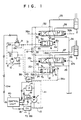
- Fig. 1 shows an overall arrangement of a load-sensing hydraulic drive circuit and a control system of the present invention.
- the load-sensing hydraulic drive circuit comprises a variable displacement hydraulic pump 1 of the swash plate type, for example, first and second hydraulic actuators 2, 3 driven by hydraulic fluid delivered from the hydraulic pump 1, a first flow control valve 4 and a first pressure balance valve 6 for pressure compensation both disposed between the pump 1 and the first actuator 2 to control the flow rate and direction of hydraulic fluid supplied to the first actuator 2 from the pump 1, and a second flow control valve 5 and a second pressure balance valve 7 for pressure compensation both disposed between the pump 1 and the second actuator 3 to control the flow rate and direction of hydraulic fluid supplied to the second actuator 3 from the pump 1.
- a variable displacement hydraulic pump 1 of the swash plate type for example, first and second hydraulic actuators 2, 3 driven by hydraulic fluid delivered from the hydraulic pump 1
- a first flow control valve 4 and a first pressure balance valve 6 for pressure compensation both disposed between the pump 1 and the first actuator 2 to control the flow
- the first pressure balance valve 6 is connected at its inlet side to the pump 1 through a hydraulic fluid supply line 20, and at its outlet side to the flow control valve 4 through a line with a check valve 22.
- the flow control valve 4 is connected at its inlet side to the pressure balance valve 6 and also to a tank 10 through a return line 24, and at its outlet side to the first actuator 2 through main lines 25, 26.
- the second pressure balance valve 7 is connected at its inlet side to the pump 1 through a line 21 and the hydraulic fluid supply line 20, and at its outlet side to the flow control valve 5 through a line with a check valve 23.
- the flow control valve 5 is connected at its inlet side to the pressure balance valve 7 and also to the tank 10 through a return line 29, and at its outlet side to the second actuator 3 through main lines 27, 28.
- the pressure balance valve 6 is of a pilot operated type having two closing-direction working pilot pressure chambers 6a, 6b and an opening-direction working pilot chamber 6c located in opposite relation.
- the inlet pressure of the flow control valve 4 is applied to one 6a of the two closing-direction working pilot pressure chambers 6a, 6b through a line 30, the outlet pressure of a proportional solenoid valve 9 (later described) is applied to the other pressure chamber 6b through a line 31, and the pressure (later described) between the flow control valve 4 and the first actuator 2 is applied to the opening-direction working pilot pressure chambers 6c through a line 32a.
- the pressure balance valve 6 further includes a spring 6d for urging the valve 6 in the opening direction.
- the pressure balance valve 7 is also constructed in a like manner. More specifically, the pressure balance valve 7 is of a pilot operated type having two closing-direction working pilot pressure chambers 7a, 7b and an opening-direction working pilot chamber 7c located in opposite relation.
- the inlet pressure of the flow control valve 5 is applied to one 7a of the two closing-direct ion working pilot pressure chambers 7a, 7b through a line 33
- the outlet pressure of the proportional solenoid valve 9 is applied to the other pressure chamber 7b through a line 34
- the pressure between the flow control valve 5 and the second actuator 3 is applied to the opening-direction working pilot pressure chambers 7c through a line 35a.
- the pressure balance valve 7 further includes a spring 7d for urging the valve 7 in the opening direction.
- the pressure balance valve 6 operates as follows. When the pressure of the proportional solenoid valve 9 is 0 (zero), the pressure balance valve 6 is subjected to the inlet pressure of the flow control valve 4 introduced to its pilot chamber 6a through the line 30, in one direction, and to the outlet pressure of the flow control valve 4 introduced to its pilot chamber 6c through the line 32a and the resilient urging force of the spring 6d, in the opposite direction. Therefore, the pressure balance valve 6 always controls the flow rate from the pump 1 so that the differential pressure between the inlet pressure and the outlet pressure of the flow control valve 4 is held a constant value corresponding to the resilient urging force of the spring 6d.
- the pressure balance valve 6 functions as a flow control valve for pressure compensation.
- the pressure balance valve 7 also operates in a like manner.
- the proportional solenoid valve 9 when the proportional solenoid valve 9 produces a pressure, this pressure is transmitted to the pressure balance valves 6, 7 through the lines 31, 34 and acts to counter the resilient urging forces of the opposing springs 6d, 7d. Stated otherwise, the pressure balance valves 6, 7 are each so controlled as to reduce the differential pressure between the inlet pressure and the outlet pressure of the flow control valves 4, 5 in proportion to a pressure rise in the line 31, 34, and hence the flow rate through the flow control valves 4, 5 is reduced. Thus, controlling the pressure of the proportional solenoid valve 9 makes it possible to restrict the flow rates through the flow control valves 4, 5 and carry out total consumable flow compensating control thereof.
- the flow control valves 4, 5 are of a pilot operated type having opposed pilot chambers connected to pilot lines 36a, 36b and 37a, 37b, respectively, and are controlled with pilot pressures transmitted through pilot lines in response to operation signals from the respective control levers (not shown).
- the flow control valve 4 and the pressure balance valve 6 jointly constitute a single pressure com pensated flow control valve.
- the operation signal from the associated control lever gives a throttle opening command value for the flow control valve 4, while the pressure applied to the pressure balance valve 6 from the proportional solenoid valve 9 and the setting value of the spring 6d give a command value for the differential pressure across the flow control valve 4.
- the throttle opening command value and the differential pressure command value for the flow control valve 4 determine a consumable flow rate that is to be passed from the pressure compensated flow control valve 4, 6 to the hydraulic actuator 2, and the throttle opening of the flow control valve and the throttle opening of the pressure balance valve are so controlled as to achieve the consumable flow rate.
- the actual flow rate through the pressure compensated flow control valve that is, the consumed flow rate through the hydraulic actuator, is thus controlled.
- the flow control valve 5 and the pressure balance valve 7 jointly constitute another pressure compensated flow control which operates in a like manner.
- pilot lines 32, 35 are Also connected to the flow control valves 4, 5 for picking up the load pressures of the first and second actuators 2, 3, respectively.
- the pilot lines 32, 35 are arranged such that they are con nected in the interior of the flow control valves 4, 5 to the return lines 24, 29 in a neutral state and to the main lines of the actuators 2, 3 coupled to the pump 1 in an operated state.
- the higher one of the pressures in the lines 32, 35 is selected by a higher-pressure selector valve 12 and then introduced to a differential pressure gauge 43 through a line 38. Further introduced to the differential pressure gauge 43 is the delivery pressure of the pump 1 through a line 39.
- the differential pressure gauge 43 detects the differential pressure between the delivery pressure of the pump 1 and the higher load pressure (maximum load pressure), and then outputs a differential pressure signal ⁇ P.
- the differential pressure gauge 43 has such a construction as shown in Fig. 2 by way of example.
- the differential pressure gauge 43 includes a body 50 having hydraulic fluid supply ports 47, 48 connected to the lines 39, 39, respectively, and a hydraulic fluid discharge port 49 connected to the tank 10 through a line 41, a cylinder 51 fitted in the body 50, a piston 52 accommodated in the cylinder 51 and having two pressure receiving surfaces 52a, 52b of equal area which are opposite to each other and subjected to the different pressures from the supply ports 47, 48, respectively, a shaft 53 made of a non-magnetic substance and transmitting a displacement and force of the piston 52, a spring 54 accommodated in the cylinder 51 for receiving the force of the piston 52 and giving a displacement proportional to the received force to the piston 52, a case 55 made of a non-magnetic substance and fitted to the cylinder 51, a core 56 made of a magnetic substance, attached to the distal end
- the pump delivery pressure P and the maximum load pressure Pam act on the pressure receiving surfaces 52a, 52b of the piston 52 through the supply ports 47, 48, respectively.
- the force of A x (P - Pam) acts on the piston 52 upward in the figure because of P > Pam. That force causes the piston 52 to be displaced against the springs 54, 60 which are in their pre-compressed state to resiliently support the piston 52, so does the core 56.
- the displacement sensor 57 converts the displacement to an electric signal, and the amplified signal is output from the amplifier 59.
- the displacement sensor 57 is preferably of a contactless type such as a differential transformer type or magnetic resistor element type, for example, because of the presence of oil deposited around the core 56.
- the shaft 53 and the case 55 are both made of a non-magnetic substance.
- the displacement sensor of any such type has a linear relationship between the displacement S and an electric signal level E, i.e., a simple proportional relationship.
- the electric signal level E has a value proportional to the differential pressure (P - Pam) between the pump delivery pressure and the maximum load pressure, thereby providing the differential pressure signal ⁇ P.
- the spring 60 may be dispensed with.
- a pressure detector 14 for detecting the delivery pressure of the pump 1 to output a pressure signal P.
- the pump 1 is provided with an inclination angle gauge 15 which detects an inclination angle of the displacement volume varying mechanism such as a swash plate and outputs an inclination angle signal Q ⁇ .
- the pump 1 is controlled substantially constant in the rotational speed thereof, and thus the inclination angle signal Q ⁇ indicates the delivery amount of the pump 1.
- the delivery amount of the pump 1 is controlled by a delivery amount control 16 coupled with the displacement volume varying mechanism.
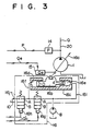
- the delivery amount control 16 can be constructed in the form of an electro-hydraulic servo-type hydraulic drive device as shown in Fig. 3, for example.
- the delivery amount control 16 has a servo piston 16b which drives a displacement volume varying mechanism 16a, such as a swash plate, swash shaft or the like, of the variable displacement hydraulic pump 1, the servo piston 16b being accommodated in a servo cylinder 16c.
- a cylinder chamber of the servo cylinder 16 is divided by a servo piston 16b into a left-hand chamber 16d and a righthand chamber 16e, and the lefthand chamber 16d is formed to have the cross-sectional area D larger than that d of the righthand chamber 16e.
- Designated at 8 is the pilot pump or hydraulic source for supplying hydraulic fluid to the servo cylinder 16.
- the hydraulic source 8 and the lefthand chamber 16d of the servo cylinder 16c is intercommunicated through a line 16f
- the hydraulic source 8 and the righthand chamber 16e of the servo cylinder 16c is intercommunicated through a line 16i, these lines 16f, 16i being communicated to the tank 10 through a return line 16j.
- a solenoid valve 16g is disposed in the line 16f intercommunicating the hydraulic source 8 and the lefthand chamber 16d of the servo cylinder 16c
- another solenoid valve 16h is disposed in the return line 16j.
- solenoid valves 16g, 16h are normally-closed solenoid valves (which have a function to automatically return to a closed state when deenergized) and switched in their state with a load-sensing control signal Q′o from a control unit 40 later described.
- the inclination angle signal Q ⁇ output from the inclination angle gauge 15 is controlled to have a level corresponding to a target delivery amount Qo calculated by the control unit 40, as described later.
- the proportional solenoid valve 9 can be constructed as shown in Fig. 4 by way of example.
- the illustrated proportional solenoid valve is constituted by a proportional solenoid pressure-reducing valve, and includes a proportional solenoid part 62 and a pressure-reducing valve part 63.
- the solenoid part 62 has a known structure comprising a solenoid and an iron core (both not shown), the solenoid having terminals 64a, 64b. Input to these terminals 64a, 64b is a total consumable flow compensating control signal Qns, described later, from the control unit 40.
- the pressure-reducing valve part 63 includes a body 71 having a hydraulic supply port 67 connected to an auxiliary pump 8 through a supply line 66, a hydraulic fluid discharge port 69 connected to the tank 10 through a return line 68, and a hydraulic outlet port 10 connected to the pilot lines 31, 34, a spool 72 disposed in the body 71, having end faces 72a, 72b opposite to each other and formed with an internal passage 72c, and a push rod 73 engaging at one end with the iron core of the proportional solenoid part 62 and abutting at the other end against the end face 72a of the spool 72.
- the spool 72 When the force acting on the end face 72b exceeds the force pressing the push rod 73 (i.e., the force induced on the iron core of the solenoid part 62), the spool 72 now moves leftward to communicate the internal passage 72c with the discharge port 69, so that the outlet port 70 and the discharge port 69 are communicated with each other through the internal passage 72c. As a result, the hydraulic pressure in the outlet port 70 is reduced and the force acting on the end face 72b of the spool 72 is also reduced. When the force acting on the end face 72b becomes smaller than the force pressing the push rod 73, the spool 72 is moved rightward again in the figure.
- the pressure in the supply line 66 is designed to always stand at a constant level set by a relief valve 11.
- the pressure signal P from the pressure detector 14, the inclination angle signal Q ⁇ from the inclination angle gauge 15, and the differential pressure signal ⁇ P from the differential pressure gauge 43 are input to the control unit 40 which creates the total consumable flow compensating control signal Qns and the load-sensing control signal Q′o, and then outputs them to the proportional solenoid valve 9 and the delivery amount control 16, respectively.
- the control unit 40 comprises a microcomputer and includes, as shown in Fig. 5, an A/D converter 40a for converting the pressure signal P output from the pressure detector 14, the inclination angle signal Q ⁇ output from the inclination angle gauge 15, and the differential pressure signal ⁇ P output from the differential pressure gauge 43 to respective digital signals, a central processing unit 40b, a memory 40C for storing a program for the control procedure, a D/A converter 40d for outputting analog signals, an I/O interface 40e for outputting signals, an amplifier 40F connected to the proportional solenoid valve 9, and amplifiers 40g, 40h connected to the solenoid valves 16g, 16h, respectively.
- the control unit 40 calculates a delivery amount target value Qo for the variable displacement hydraulic pump 1 based on the control program stored in the memory 40c, and then outputs the load-sensing control command signal Q′o from the amplifiers 40g, 40h to the solenoid valves l6g, 16h of the delivery amount control 16, respectively, through the I/O interface 40e.
- the position of the servo piston 3 is controlled with on-off servo control using the electrohydraulic servo technique so that the inclination angle signal Q ⁇ has a level corresponding to the delivery amount target value Qo, as explained above.
- the control unit 40 also calculates a total consumable flow compensating value based on the control program stored in the memory 40C, and outputs the control command signal Qns from the amplifier 40f to the solenoid proportional control valve 9 through the D/A converter 40d. This causes the proportional solenoid valve 9 to produce the pressure in proportion to the command signal Qns, as explained above.
- Fig. 6 is a flowchart showing the control program stored in the memory 40c of the control unit 40.
- the control unit 40 reads and stores therein, as conditions of the hydraulic drive system, the delivery pressure P of the pump 1, the inclination amount Q ⁇ of the pump 1, and the differential pressure ⁇ P between the maximum load pressure Pam and the delivery pressure P from the outputs of the pressure detector 14, the inclination angle gauge 15 and the differential pressure gauge 43, respectively.
- an input limiting target delivery amount QT is determined based on both the output pressure P of the pressure detector 14 and an input torque limiting function f(P) previously input in the memory.
- Fig. 7 shows the input torque limiting function.
- the X-axis represents the output pressure P and the Y-axis represents the input limiting target delivery amount QT based on the input torque limiting function f(P).
- Input torque of the pump 1 is in proportion to the product of the delivery pressure P and the inclination amount Q ⁇ of the pump 1. Accordingly, the input torque limiting function f(P) is given by a hyperbolic curve or an approximate hyperbolic curve.
- the input limiting target delivery amount QT can be determined.
- Fig. 8 is a block diagram showing a method of determining the differential pressure target delivery amount Q ⁇ p from the differential pressure signal ⁇ P of the differential pressure gauge 43.
- this example is to calculate the differential pressure target delivery amount Q ⁇ p using the integration control technique applied to a deviation between the target differential value ⁇ Po and the actual difference pressure.
- a block 120 calculates KI( ⁇ Po - ⁇ P) from the differential pressure ⁇ P for determining an increment ⁇ Q ⁇ p of the differential pressure target delivery amount per one unit of control cycle time, and a block 121 obtains the equation (2) by adding the above ⁇ Q ⁇ p and the delivery amount target value Qo-1 in the preceding control cycle.
- Q ⁇ p has been determined using the integral control technique applied to ⁇ Po - ⁇ P in the foregoing embodiment, it may be determined using any other suitable technique.
- the differential pressure target delivery amount Q ⁇ p is determined in the step 102.
- the target delivery amount deviation ⁇ Q between the differential pressure target delivery amount Q ⁇ p and the input limiting target delivery amount QT is determined.
- a next step 104 determines whether the deviation ⁇ Q is positive or negative. If the deviation ⁇ Q is positive, the process goes to a step 105 to select QT as the delivery amount target value Qo. If the deviation ⁇ Q is negative, it goes to a step 106 to select Q ⁇ p as the delivery amount target value Qo.
- the lesser of the differential pressure target delivery amount Q ⁇ p and the input limiting target delivery amount QT is selected as the delivery amount target value Qo, so that the delivery amount target value Qo will not exceed the input limiting target delivery amount QT determined by the input torque limiting function f(P).
- Fig. 9 is a block diagram showing the method to calculate the compensation value Qns from the target delivery amount deviation ⁇ Q.
- the compensation value increment ⁇ Qns per one unit of control cycle time i.e., KIns ⁇ ⁇ Q
- KIns ⁇ ⁇ Q the compensation value increment ⁇ Qns per one unit of control cycle time
- the increment is then added in an adder 131 to the compensation value Qns-1 output in the preceding control cycle, thereby to determine an intermediate value Q′ns.
- Qnsmax and Q′nsc are values determined by the maximum inclination angle of swash plate of the pump 1, i.e., the maximum delivery amount thereof.
- the compensation value Qns has been determined using the integral control technique in the foregoing embodiment, the relationship between Qns and ⁇ Q may be determined using the proportional control technique or the proportional plus integral control technique, as with the above case of the differential pressure target delivery amount Q ⁇ p.
- the control unit 40 creates the command signal Q′o for the delivery amount control 16 based on the delivery amount target value Qo of the pump 1 and the inclination angle signal Q ⁇ output from the inclination angle gauge 15 which are obtained in the steps 105, 106, respectively.
- the command signal Q′o is output to the delivery amount control 16 through the I/O interface 40e and the amplifiers 40g, 40h of the control unit 40, as shown in Fig. 5, so that the inclination amount Q ⁇ of the pump 1 becomes equal to the delivery amount target value Qo.
- Fig. 10 shows a flowchart of the control process carried out in the step 108.
- a step 141 determines whether an absolute value of the deviation Z is larger or smaller than a value ⁇ preset for specifying the dead zone. If the absolute value of the deviation Z is larger than the preset value ⁇ , the process flow goes a step 142 to determine whether the deviation Z is positive or negative.
- the process flow goes to a step 143 for outputting the command signal Q′o which turns ON the solenoid valve 16g of the delivery amount control 16 and turns OFF the solenoid valve 16h thereof.
- the inclination angle of the pump 1 is increased so that the inclination angle signal Q ⁇ is controlled to be coincide with the target command signal Qo.
- the process flow goes to a step 144 for outputting the command signal Q′o which turns OFF the solenoid valve 16g and turns ON the solenoid valve 16h. This reduces the inclination angle of the pump 1, so that the inclination angle signal Q ⁇ is controlled to be coincide with the target command signal Qo.
- the process flow goes a step 145 where the solenoid valves 16g and 16h are both turned OFF. This causes the inclination angle of the pump 1 to stand constant.
- the differential pressure target delivery amount Q ⁇ p is selected as a delivery amount target value Qo in the step 106 if the differential pressure target delivery amount Q ⁇ p is smaller than the input limiting target delivery amount QT, the delivery amount of the pump 1 is controlled for being equal to the differential pressure target delivery amount Q ⁇ p, and the differential pressure between the delivery pressure of the pump 1 and the maximum load pressure out of the plural actuators 2, 3 is held constant.
- the load-sensing control is effected.
- the input limiting target delivery amount QT is selected as a delivery amount target value Qo in the step 105, and therefore the delivery amount of the pump is so controlled as not to exceed the input limiting target delivery amount QT.
- the delivery amount of the pump is subjected to input limiting control.
- an output current to the proportional solenoid valve 9 through the D/A converter 40d and the amplifier 40f of the control unit 40, as shown in Fig. 5, is controlled to be equal to Qns for controlling the pressure balance valves 6, 7 shown in Fig. 1.
- the target current Qns is set 0 in the block 132 (Fig. 9) in the step 107.
- the target current Qns is increased with an increase of the target delivery amount deviation ⁇ Q until the maximum value of Qnsmax in the step 107, so that the throttle openings of the pressure balance valves 6, 7 are restricted in response to increase of the target delivery amount deviation ⁇ Q.
- the total consumable flow compensating control is effected.
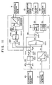
- a block 200 corresponds to the step 101 in Fig. 6 in that it calculates the input limiting target delivery amount QT based on the input torque limiting function shown in Fig. 7.
- Blocks 201, 202, 203 correspond to the step 102.
- the addition block 201 and the proportional calculation block 202 correspond to the differential pressure target delivery amount increment calculation block 120 in Fig. 8, respectively
- the addition block 203 corresponds to the adder 121 in Fig. 8.
- the differential pressure target value Q ⁇ p is calculated through these three blocks.
- a block 204 corresponds to the steps 104, 105, 106 in Fig. 6 in that it selects the lesser one between the two target delivery amounts QT and Q ⁇ p as the delivery amount target value Qo.
- Blocks 205, 206, 207, 208 correspond to the step 107 in Fig. 6.
- the addition block 205 and the proportional calculation block 206 correspond to the total consumable flow compensation value increment calculation block 131 in Fig. 9, respectively
- the addition block 207 corresponds to the limiter 132 in Fig. 9.
- the total consumable flow compensation value Qns is calculated through those three blocks.
- Blocks 209, 210, 211 correspond to the step 108 in Fig. 6.
- the addition block 209 corresponds to the step 140 in Fig. 10
- the blocks 210, 211 correspond to the steps 141 - 145 in Fig. 10 in outputting the command signals Q′o to the respective solenoid valves 16g, 16h.
- the input limiting target delivery amount QT and the differential pressure target delivery amount Q ⁇ p are calculated independently of each other as the target delivery amount Qo of the pump 1, and only if the differential pressure target delivery amount Q ⁇ p exceeds the input limiting target delivery amount QT, the total consumable flow compensating control is carried out. Therefore, when the differential pressure target delivery amount is smaller than the input limiting target delivery amount and hence there is no need of total consumable flow compensating control, the total consumable flow compensating control will not be carried out even if the differential pressure ⁇ P is reduced due to a response lag in the delivery amount control 16 for the pump 1, with the result that the throttle openings of the pressure balance valves 6, 7 will not be restricted.
- the flow control valves 4, 5 can provide the flow rates as exactly specified by the associated control levers. Further, the load-sensing control and the total consumable flow compensating control are not effected concurrently, and this prevents the hunting phenomenon due to interference therebetween, and hence ensures stable control of the hydraulic actuators 2, 3.
- QT has been determined from the delivery pressure P and the input torque limiting function f(P).
- means for determining a speed deviation ⁇ N between the target speed set by an accelerator for a prime mover for driving the pump and the actual speed of the prime mover and to employ, as the input limiting function for the pump, an input torque limiting function f1(P, ⁇ N) with parameters of the delivery pressure P of the pump 1 and the speed deviation ⁇ N of the prime mover, thereby determining QT based on the speed deviation ⁇ N, the delivery pressure P and the input torque limiting function f1 (P, ⁇ N) as disclosed in EP-B1-0062072.
- Figs. 12 and 13 show such an embodiment in which the identical members to those in Fig. 1 are designated at the same reference numerals.
- a fuel injection pump 151 for driving a plurality of pumps including a hydraulic pump 1.
- Fuel is supplied to the engine 150 by means of a fuel injection pump 151.
- the target speed for the engine 150 is set by an accelerator 152.
- the engine 150 is provided on its output shaft with a speed sensor 153 for detecting the rotational speed of the engine 150.
- a target engine speed signal Nr from the accelerator 152 and an actual engine speed signal Ne from the speed sensor 153 are input to a control unit 154 for the engine 150 for determining an engine speed deviation ⁇ N therebetween.
- Also input to the control unit 154 is a rack displacement signal from a rack displacement detector 155 for the fuel injection pump 151.
- the control unit 154 Based on the engine speed deviation ⁇ N and the rack displacement signal, the control unit 154 calculates a target rack displacement for the fuel injection pump 151 and then outputs a rack operating signal to the fuel injection pump 151. Further, the control unit 154 outputs the engine speed deviation ⁇ N to the control unit 40 for the hydraulic pump 1 as well.
- the control unit 40 previously stores therein, as the input limiting function for the pump 1, an input torque limiting function fl(P, ⁇ N) with parameters of the delivery pressure P of the pump 1 and the engine speed deviation ⁇ N of the internal combustion engine 150.
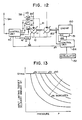
- Fig. 13 shows the input torque limiting function f1(P, ⁇ N).
- the input torque limiting function fl(P, ⁇ N) is to make smaller the product of the target delivery amount QT and the delivery pressure P as the engine speed deviation ⁇ N is increased, thereby controlling the target delivery amount QT.
- the input limiting target delivery amount QT is determined based on the engine speed deviation ⁇ N, the delivery pressure P and the input torque limiting function f1(P, ⁇ N) By so doing, input torque of the pump 1 can be controlled for being reduced with the increasing engine speed deviation ⁇ N.
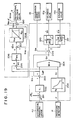
- a control block diagram of this embodiment is shown in Fig. 14.
- a block 250 compares the actual engine speed signal Ne from the speed sensor 153 with the target engine speed signal Nr from the accelerator 152 to calculate the engine speed deviation ⁇ N.
- a block 251 is an input limiting target delivery amount calculation block which inputs the delivery pressure P and the engine speed deviation ⁇ N for calculating the input limiting target delivery amount QT from the input torque limiting function shown in Fig. 13.
- Other blocks are the same as those in Fig. 11.
- the input torque limiting control of the pump 1 is performed such that the product of the target delivery amount QT and the delivery pressure P is made smaller with the increasing engine speed deviation ⁇ N. It is thus possible to effectively utilize the output horse of the engine 150 at maximum.
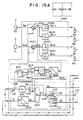
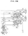
- FIG. 15A and 15B A third embodiment of the present invention will be described with reference to Figs. 15A and 15B.
- the components similar to those in Figs. 1 and 11 are denoted at the same reference numerals.
- the flow control valve rather than the pressure balance valve is controlled directly based on the total consumable flow compensation value Qns.
- the pressure balance valves 6, 7 of the respective pressure compensated flow control valves are controlled using the compensation value Qns.
- the consumable flow rates, that are to be passed to the hydraulic actuators 2, 3 through the respective pressure compensated flow control valves are determined based on both the throttle opening command values for the flow control valves 4, 5 given by the operation signal from the associated control levers and the differential pressure command values across the flow control valves given to the pressure balance valves 6, 7 as the compensation values Qns.
- the operation signals of the control levers are modified using the compensation value Qns to include the differential pressure command values into the respective throttle opening command values for the flow control valves 6, 7, whereby the consumable flow rates are determined by the resulting throttle opening command values.
- Figs. 15A and 15B denoted at 70, 71 are control levers which output operation signals Qa1, Qa2 of the hydraulic actuators 2, 3 when operated, respectively.
- a control unit 40A serves, in addition to the function of the control unit 40 in Fig. 1, to input the operation signals Qa1, Qa2 from the control levers 70, 71, convert the input signals to drive signals Qa1′+, Qa1′- and Qa2′+, Qa2′- for proportional solenoid valves 9a - 9d, and then output them, respectively.
- the proportional solenoid valves 9a-9d produce pilot pressures for operating the flow control valves 4, 5 proportional to the drive signals Qa1′+, Qa1′-, Qa2′+, Qa2′- output from the control unit 40A.
- the flow control valves 4, 5 are controlled in the opening directions and degrees thereof with the pilot pressures output from the proportional solenoid valves 9a - 9d. For example, when the drive signal Qa1′+ is output to the flow control valve 4, the flow control valve 4 is switched to the righthand side as shown with the pilot pressure output from the proportional solenoid valve 9a to take the throttle opening in proportion to Qa1′+. Similarly, when the drive signal Qa1′- is output, the flow control valve 4 is switched to the lefthand side as shown.
- the pressure balance valves 6A, 7A are adjusted in their throttle openings to make the differential pressures between inlets and outlets of the flow control valves 4, 5 equal to values set by springs 6d, 7d, respectively.
- the flow rates specified by the drive signal Qa1′- to Qa2′- are supplied to the actuators 2, 3.
- Fig. 15A the control procedure carried out in the control unit 40A is represented in a control block diagram similar to Fig. 11. Among the control procedure, the steps for the load-sensing control and up to calculation of Qns in the total consumable flow compensating control are the same as those for the control unit 40 in Fig. 11. Operation of the control unit 40A will be described below by referring to the remaining part of the control block diagram.
- the control unit 40A determines an operation signal modifying factor ⁇ from Qns.
- the relationship between the factor ⁇ and Qns is, for example, such that ⁇ is 1 near around 0 of Qns and then decreases as Qns increases, as shown in a block 400. Note that the minimum value of ⁇ should be larger than 0.
- the operation signals Qa1, Qa2 from the control levers 70, 72 which have been input through the A/D converter 40a (see Fig. 5), are multiplied by the operation signal modifying factor ⁇ in multipliers 401a, 401b for generating the modified operation signals Qa1′, Qa2′, respectively.
- the modified operation signals Qa1′, Qa2′ are separated into respective +/- pairs by limiters 402a - 402d to generate the proportional solenoid drive signals Qa1′+, Qa1′-, Qa2′+, Qa2′- which are output to the proportional solenoid valves 9a - 9d.
- the compensation value Qns is 0 and hence the operation signal modifying factor becomes 1. Therefore, the modified operation signals Qa1′, Qa2′ are coincident with the operation signals Qa1, Qa2 from the control levers 70, 71, and the flow control valves comes into the same conditions as the case where they are operated by the operation signals Qa1, Qa2.
- the pump 1 is controlled with the input limiting target delivery amount QT. Stated otherwise, when the pump delivery pressure is saturated and the differential pressure target delivery amount Q ⁇ p becomes larger than the input limiting target delivery amount QT, the operation signal modifying factor ⁇ is made smaller as the compensation value Qns gradually increases from 0. Thus, the operation signals Qa1, Qa2 are multiplied by the operation signal modifying factor ⁇ less than 1 in the multipliers 401a, 401b, so that the modified operation signals Qa1′, Qa2′ are gradually reduced. As a result, the flow rates through the flow control valves 4, 5 are also reduced correspondingly.
- the modifying factor ⁇ When the modifying factor ⁇ is reduced down to a level at which the total value of the modified operation signals Qa1′, Qa2′ coincides with the input limiting target delivery amount QT, the differential pressure signal ⁇ P is restored and the differential pressure target delivery amount Q ⁇ p is reduced to be coincident with the input limiting target delivery amount QT. Therefore, the target delivery amount deviation ⁇ Q becomes 0, whereupon an increase of the compensation value Qns and a reduction of the modifying factor ⁇ are brought into end.
- operation signals from the control levers have been described as electric signals in the above embodiment, those operation signals may be replaced by hydraulic pilot signals and the hydraulic pressures of the pilot signals may be regulated through a proportional solenoid valve using the operation signal modifying factor ⁇ .
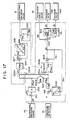
- a fourth embodiment of the present invention will be described with reference to Fig. 16.
- the delivery amount of the pump is controlled to the input limiting target delivery amount QT for preventing interference between the load-sensing control and the total consumable flow compensating control
- the differential pressure target delivery amount Q ⁇ p is increased again above the input limiting target delivery amount QT, which in turn in creases the compensation value Qns and hence reduces the flow rates through the flow control valves 4, 5. Then, the differential pressure target delivery amount Q ⁇ p is increased once again.
- the above may occur repeatedly. In short, there is a possibility that the load-sensing control and the total consumable flow compensating control proceed simultaneously and interfere with each other, which leads to a hunting phenomenon.
- FIG. 16 A control block diagram for a control unit 40B of this embodiment is shown in Fig. 16. In the figure, blocks of the same number as those in Fig. 11 carry out the same functions. Note that the component configuration in this embodiment is the same as that in Fig. 1.
- a block 300 determines whether the total consumable flow compensating control is being performed or not, and then sets a total consumable flow compensating flag FQns. This decision is made based on the total consumable flow compensation value Qns such that the total consumable flow compensating control is not being when Qns is equal to or less than 0, and is being when Qns is above 0.
- the flag FQns is set to 1 or 0 dependent on under or not under the total consumable flow compensating control.
- a block 204A is a minimum value selection block which determines which of the input limiting target delivery amount QT and the differential pressure target delivery amount Q ⁇ p is or smaller, and then selects and outputs the smaller one as a delivery amount target value Qor.
- a block 301 is a delivery amount target value selector switch for the pump.
- the switch Upon receiving the total consumable flow compensating flag FQns, the switch selects the delivery amount target value Qor selected by the minimum value selection block 204A when FQns is 0, and the input limiting target delivery amount QT when FQns is 1, and then the selected one as a delivery amount target value Qo.
- the differential pressure target delivery amount Q ⁇ p is less than QT and the block 204A selects the differential pressure target delivery amount Q ⁇ p as the selected delivery amount target value Qor. Simultaneously, the total consumable flow compensation value Qns becomes 0. At this time, the flag FQns is set to 0 and the delivery amount target value selector switch 301 selects the selected delivery amount target value Qor as the delivery amount target value Qo. As a result, the pump 1 is controlled to the differential pressure target delivery amount Q ⁇ p.
- the differential pressure target delivery amount Q ⁇ p exceeds QT and hence the block 204A selects QT as the delivery amount target value Qor.
- the target delivery amount deviation ⁇ Q becomes positive (+) and the compensation value Qns is increased.
- the flag FQns is set to 1 and the delivery amount target value selector switch 301 selects the input limiting target delivery amount QT as the delivery amount target value Qo.
- the pump 1 is controlled to the input limiting target delivery amount QT.
- the flow rates through the flow control valves 4, 5 are reduced using the compensation value Qns to be coincident with the input limiting target delivery amount QT, with the result that the saturated condition is solved.
- Fig. 16 operates in a like manner to that of Fig. 11.
- the block 204A selects Q ⁇ p as the delivery amount target value Qor.
- the target delivery amount deviation ⁇ Q becomes negative (-)
- the total consumable flow compensation value Qns remains positive (+) and the flag FQns is held at 1 because Qns is gradually reduced in a transient range. Therefore, the delivery amount target value selector switch 301 selects the input limiting target delivery amount QT as the delivery amount target value Qo and the pump 1 is hence held controlled to QT.
- the differential pressure target delivery amount Q ⁇ p becomes smaller than QT. But, the delivery amount target value Qo is held at QT because the flag FQns remains at 1 while the compensation value Qns is assuming a positive (+) value. Therefore, Qns is gradually reduced still in the condition the delivery amount of the pump 1 is held at QT, and this reduction continues until Qns becomes 0.
- the delivery amount target value selector switch 301 selects the differential pressure target delivery amount Q ⁇ p as the delivery amount target value Qo. Thereafter, Q ⁇ p is controlled to be coincident with the total of demand flow rates commanded by the operation signals for the flow control valves 4, 5.
- FIG. 17 A fifth embodiment of the present invention will be described with reference to Fig. 17. This embodiment is different from that of Fig. 16 in that the input limiting target delivery amount is calculated integrally rather than proportionally.
- the component arrangement is, therefore, similar to that shown in Fig. 1 as with the embodiment of Fig. 16.
- a block 500 is a target delivery pressure calculation block which inputs the preceding delivery amount target value Qo-1 and calculates a currently allowable target delivery pressure Pr from the preset input limiting torque for the pump 1.
- the target delivery pressure Pr is sent to a differential pressure calculation block 501 where the target delivery pressure Pr is compared with the current delivery pressure P to calculate a differential pressure ⁇ P.
- the differential pressure ⁇ P is multiplied by the integration gain KIp in an input limiting target delivery amount increment calculation block 502 to calculate an increment ⁇ Qps of the input limiting target delivery amount per one unit of control cycle time.
- the increment ⁇ Qps of the input limiting target delivery amount and an increment ⁇ Q ⁇ p of the differential pressure target delivery amount are sent to a delivery amount increment minimum value selector block 204B that determines which of the two increments is smaller and then outputs the smaller one as a target delivery amount increment ⁇ Qor.
- the delivery amount increment selector switch 301A selects the target delivery amount increment ⁇ Qor selected by the delivery amount increment minimum value selector block 204B when FQns is 0 and the input limiting target delivery amount increment ⁇ Qps when FQns is 1, and then outputs the selected one as a delivery amount increment ⁇ Qo.
- the delivery amount increment ⁇ Qo selected by the delivery amount increment selector switch 301A is added in a block 503 to the delivery amount target value Qo-1 calculated in the preceding control cycle for calculating the delivery amount target value Qo in this cycle.
- the input limiting target delivery amount increment ⁇ Qps and the differential pressure target delivery amount ⁇ Q ⁇ p are sent to a block 204 for calculating a signal indicative of the difference therebetween as the target delivery amount deviation ⁇ Q.
- the flow through the blocks 201, 202, 204B, 301A, 503 are the same as that through the blocks 201, 202, 203, 204A, 301 in the load-sensing control of Fig. 16 for calculating the differential pressure target delivery amount.
- the flow through the blocks 500, 501, 502, 204B, 301A, 503 is substituted for that through the blocks 200, 204A, 301 in Fig. 16 for calculating the input limiting target delivery amount.
- While the proportional type control is performed in Fig. 16 by directly calculating the input limiting target delivery amount QT from the delivery pressure P of the pump 1, the input limiting target value is calculated in the embodiment of Fig. 17 under the integral type control such that the delivery amount increment ⁇ Qps necessary for control following the target delivery pressure Pr computed from the input limiting torque of the pump is calculated and then added to the preceding delivery amount target value.
- minimum value selector block 204B and the selector switch 301A are designed to act on the delivery amount increment in the block diagram of Fig. 17. This is because of the following reason.
- the increment of the differential pressure target delivery amount calculated from control of the differential pressure is always compared with the increment of the input limiting target delivery amount calculated from the limiting torque, and the minimum value therebetween is added to the current pump delivery amount for always determining that the pump delivery amount should be controlled based on which one of the differential pressure and the limiting torque.
- ⁇ Q Q ⁇ p - QT
- the block 205A in Fig. 17 becomes equivalent to the block 205 in Fig. 16.
- the remaining blocks subsequent to the block 206 operates in the exactly same manner as those in Fig. 16.
- the total consumable flow compensation value Qns is determined based on the deviation ⁇ Q between the available delivery amount of the pump and the target delivery amount determined from the differential pressure, and the resulting Qns is employed to control the pressure balance valve for solving the saturated condition. Also, while the pressure balance vale is being under the total consumable flow compensating control, the pump is controlled to the input limiting target delivery amount to avoid interference with the total consumable flow compensating control
- the new target delivery amount Qo is always calculated from the preceding target delivery amount Qo-1 and the transition is hence smoothed when the pump is shifted from the condition where is controlled following the differential pressure target delivery amount to the condition where it is controlled following the input limiting target delivery amount, or vice versa.
- the pump will not be subject to any rush operation and can make control more stably at the time of shifting the control mode.
- FIG. 18 A sixth embodiment of the present invention will now be described with reference to Fig. 18.
- the same components as those shown in Fig. 11 are denoted at the same reference numerals.
- This embodiment is different from the foregoing ones in arrangement of the block of calculating the total consumable flow compensation value Qns.
- the output ⁇ P ⁇ of the half-wave rectifier 601 and the differential pressure deviation ⁇ P′ are both input to a signal selector switch 602.
- the signal selector switch 602 selects the value ⁇ P′ when ⁇ Q is positive, i.e., in case of the differential pressure target delivery amount Q ⁇ P ⁇ the input limiting target delivery amount QT, and the value ⁇ P ⁇ when ⁇ Q is negative, i.e., in case of Q ⁇ p ⁇ QT, followed by outputting the selected one as an increment ⁇ Q′ns of an intermediate value.
- This increment ⁇ Q′ns is added to the output Qns-1 in the just preceding control cycle in the adder 207 to obtain the intermediate value Q′ns.
- the value Q′ns is then sent to the limiter 208.
- the limiter 208 is to keep the value Q′ns from exceeding the maximum limit and outputs it as the total consumable flow compensation value Qns.
- the signal selector switch 602 selects ⁇ P′ (>0) as the intermediate value Q′ns and the pressure compensated flow control valve is controlled for compensation using the compensation value Qns resulted from the positive ⁇ P′.
- this embodiment can also achieve the similar function to that as obtainable with the first embodiment.
- FIG. 19 A seventh embodiment of the present invention will be described with reference to Fig. 19. Likewise, the same components in Fig. 19 as those shown in Fig. 11 are denoted at the same reference numerals. This embodiment is different from the foregoing ones in that the total consumable flow compensation value Qns is further modified.
- an adder 610 is provided in this embodiment to subtract a small offset value Qnsof from the compensation value Qns and the resulting difference is output as a final compensation value Qnso.
- the total consumable flow rate given by Qnso becomes slightly greater than the available maximum delivery flow rate of the pump by an extent corresponding to the offset value Qnsof, and hence there produces a corresponding free flow rate in the delivery amount of the pump, which can pass into the track motor on the lower pressure side.
- Such a free flow rate can be utilized advantageously dependent on situations. For example, if the vehicle body equipped with the above track apparatus tends to turn to the left slowly because of the fact that the righthand track motor is supplied with the larger supply flow rate than the lefthand track motor due to variations in the individual components, the righthand track motor would produce larger drive torque than the lefthand track motor.
- the hydraulic pressure is more increased on the righthand side, allowing the free flow rate caused by the offset value Qnsof to pass into the lefthand track motor under the lower load pressure.
- the vehicle body is automatically released from its tendency to curve to the left and can travel straight.
- this embodiment makes it possible to solve the drawback as would be experienced in case of strictly performing the total consumable flow compensating control.
- the differential pressure target delivery amount Q ⁇ p and the input limiting target delivery amount QT are independently calculated as the target delivery amount Qo of the pump, and the total consumable flow compensating control is carried out only when the input limiting target delivery amount QT is selected. Therefore, in the condition where the delivery amount of the pump is less than its available maximum delivery amount (the input limiting target delivery amount QT), the load-sensing control is carried out, while in the condition where it reaches the available maximum delivery amount (the input limiting target delivery amount QT), the total consumable flow compensating control is carried out. This enables to smoothly increase or decrease the flow rates supplied to the respective hydraulic actuators and hence improve the operability. It is also possible to prevent a hunting phenomenon due to interference between the load-sensing control and the total consumable flow compensating control, resulting in the stable control.
- the new target delivery amount Qo is always calculated from the preceding target delivery amount Qo-1 and the transition is hence smoothed when the pump is shifted from the condition where it is controlled following the differential pressure target delivery amount Q ⁇ p to the condition where it is controlled following the input limiting target delivery amount QT, or vice versa, thereby ensuring the more stable control.
Landscapes
- Engineering & Computer Science (AREA)
- General Engineering & Computer Science (AREA)
- Structural Engineering (AREA)
- Mining & Mineral Resources (AREA)
- Civil Engineering (AREA)
- Fluid Mechanics (AREA)
- Physics & Mathematics (AREA)
- Mechanical Engineering (AREA)
- Chemical & Material Sciences (AREA)
- Combustion & Propulsion (AREA)
- Analytical Chemistry (AREA)
- Fluid-Pressure Circuits (AREA)
- Operation Control Of Excavators (AREA)
Applications Claiming Priority (2)
| Application Number | Priority Date | Filing Date | Title |
|---|---|---|---|
| JP16554/88 | 1988-01-27 | ||
| JP1655488 | 1988-01-27 |
Publications (2)
| Publication Number | Publication Date |
|---|---|
| EP0326150A1 true EP0326150A1 (fr) | 1989-08-02 |
| EP0326150B1 EP0326150B1 (fr) | 1992-10-28 |
Family
ID=11919498
Family Applications (1)
| Application Number | Title | Priority Date | Filing Date |
|---|---|---|---|
| EP89101426A Expired - Lifetime EP0326150B1 (fr) | 1988-01-27 | 1989-01-27 | Système de commande sensible à la charge pour un circuit hydraulique |
Country Status (8)
| Country | Link |
|---|---|
| US (1) | US4967557A (fr) |
| EP (1) | EP0326150B1 (fr) |
| JP (1) | JPH07103881B2 (fr) |
| KR (1) | KR930002475B1 (fr) |
| CN (1) | CN1010969B (fr) |
| AU (1) | AU600400B2 (fr) |
| DE (1) | DE68903281T2 (fr) |
| IN (1) | IN171213B (fr) |
Cited By (26)
| Publication number | Priority date | Publication date | Assignee | Title |
|---|---|---|---|---|
| EP0379595A1 (fr) * | 1988-07-08 | 1990-08-01 | Hitachi Construction Machinery Co., Ltd. | Appareil hydrodynamique |
| EP0394465A1 (fr) * | 1988-08-31 | 1990-10-31 | Hitachi Construction Machinery Co., Ltd. | Appareil d'entrainement hydraulique |
| EP0432266A4 (fr) * | 1989-01-18 | 1991-04-03 | Hitachi Construction Machinery | Unite de commande hydraulique pour engin de construction. |
| EP0419673A1 (fr) * | 1989-03-22 | 1991-04-03 | Hitachi Construction Machinery Co., Ltd. | Unite de commande hydraulique pour engins de construction et de genie civil |
| EP0440802A1 (fr) * | 1989-07-27 | 1991-08-14 | Hitachi Construction Machinery Co., Ltd. | Dispositif pour la commande d'une pompe hydraulique |
| EP0443561A1 (fr) * | 1990-02-22 | 1991-08-28 | Brueninghaus Hydromatik Gmbh | Dispositif pour ajuster la capacité d'une machine hydrostatique |
| FR2659399A1 (fr) * | 1990-02-26 | 1991-09-13 | Rexroth Mannesmann Gmbh | Commande de vanne independante de la charge, destinee a plusieurs recepteurs hydrauliques. |
| GB2250611A (en) * | 1990-11-24 | 1992-06-10 | Samsung Heavy Ind | Control system for an excavator |
| WO1992010684A1 (fr) * | 1990-12-15 | 1992-06-25 | Barmag Ag | Systeme hydraulique |
| FR2672944A1 (fr) * | 1991-02-15 | 1992-08-21 | Bennes Marrel | Distributeur proportionnel et ensemble de commande d'une pluralite de recepteurs hydrauliques comportant pour chaque recepteur un tel distributeur. |
| WO1993001417A1 (fr) * | 1991-07-04 | 1993-01-21 | Danfoss A/S | Systeme hydraulique a pompe et charge |
| FR2697295A1 (fr) * | 1992-10-22 | 1994-04-29 | Linde Ag | Système d'entraînement hydrostatique. |
| FR2697296A1 (fr) * | 1992-10-22 | 1994-04-29 | Linde Ag | Système hydrostatique d'entraînement. |
| EP0644335A1 (fr) * | 1993-03-23 | 1995-03-22 | Hitachi Construction Machinery Co., Ltd. | Moteur hydraulique pour engin de chantier hydraulique |
| DE4440304A1 (de) * | 1993-12-30 | 1995-07-06 | Samsung Heavy Ind | Gerät und Verfahren zur Steuerung des Motors und der Hydraulikpumpen eines hydraulischen Baugeräts |
| EP0765970A2 (fr) * | 1991-01-28 | 1997-04-02 | Hitachi Construction Machinery Co., Ltd. | Dispositif de commande hydraulique pour engin de chantier |
| EP0785313A1 (fr) * | 1995-12-26 | 1997-07-23 | Hitachi Construction Machinery Co., Ltd. | Système de commande hydraulique pour machine de construction hydraulique |
| EP0812964A1 (fr) * | 1996-06-12 | 1997-12-17 | Shin Caterpillar Mitsubishi Ltd. | Unité de commande pour un actuateur hydraulique |
| EP0851122A2 (fr) * | 1996-12-27 | 1998-07-01 | Shin Caterpillar Mitsubishi Ltd. | Système de commande pour pompe hydraulique |
| DE19745489A1 (de) * | 1997-10-15 | 1999-04-22 | Orenstein & Koppel Ag | System zur Lastdruckunabhängigen Steuerung und Lasthaltung mehrerer rotatorischer und/oder translatorischer Verbraucher |
| EP1162374A1 (fr) * | 2000-01-12 | 2001-12-12 | Hitachi Construction Machinery Co., Ltd. | Engin a commande hydraulique |
| DE10308289A1 (de) * | 2003-02-26 | 2004-09-09 | Bosch Rexroth Ag | LS-Wegeventilblock |
| WO2008150266A1 (fr) * | 2007-06-08 | 2008-12-11 | Deere & Company | Contrôle de mode auxiliaire électrohydraulique |
| CN103016466A (zh) * | 2012-12-24 | 2013-04-03 | 中联重科股份有限公司 | 液压供油单元、液压泵站及液压供油单元的供油控制方法 |
| EP2889433A1 (fr) * | 2013-12-20 | 2015-07-01 | Doosan Infracore Co., Ltd. | Système et procédé de commande de véhicule de chantier |
| SE2150253A1 (en) * | 2021-03-04 | 2022-09-05 | Husqvarna Ab | An energy efficient hydraulic system for construction machines |
Families Citing this family (88)
| Publication number | Priority date | Publication date | Assignee | Title |
|---|---|---|---|---|
| WO1989009343A1 (fr) * | 1988-03-23 | 1989-10-05 | Hitachi Construction Machinery Co., Ltd. | Unite d'entrainement hydraulique |
| JPH0786361B2 (ja) * | 1988-11-10 | 1995-09-20 | 株式会社ゼクセル | 油圧制御弁 |
| DE69014245T2 (de) * | 1989-01-27 | 1995-04-06 | Hitachi Construction Machinery | Steuerrungsanordnung für hydraulische fahrgetriebe. |
| KR920007650B1 (ko) * | 1989-02-20 | 1992-09-14 | 히다찌 겐끼 가부시기가이샤 | 작업기계의 유압회로장치 |
| KR940009219B1 (ko) * | 1989-03-30 | 1994-10-01 | 히다찌 겐끼 가부시기가이샤 | 장궤식차량의 유압구동장치 |
| DE69011280T2 (de) * | 1989-05-02 | 1994-11-24 | Hitachi Construction Machinery Co., Ltd., Tokio/Tokyo | Hydraulische antriebsanordnung einer bauvorrichtung. |
| DE3914904C2 (de) * | 1989-05-05 | 1995-06-29 | Rexroth Mannesmann Gmbh | Regelung für eine lastabhängig arbeitende Verstellpumpe |
| US5209063A (en) * | 1989-05-24 | 1993-05-11 | Kabushiki Kaisha Komatsu Seisakusho | Hydraulic circuit utilizing a compensator pressure selecting value |
| US5152140A (en) * | 1989-10-11 | 1992-10-06 | Hitachi Construction Machinery Co., Ltd. | Pressure compensating valve spool positioned by difference in pressure receiving areas for load and inlet pressures |
| US5101628A (en) * | 1990-01-22 | 1992-04-07 | Shin Caterpillar Mitsubishi Ltd. | Energy regenerative circuit in a hydraulic apparatus |
| EP0551513A1 (fr) * | 1990-02-28 | 1993-07-21 | Hitachi Construction Machinery Co., Ltd. | Systeme hydraulique de commande d'engin de chantier |
| JP2828490B2 (ja) * | 1990-06-19 | 1998-11-25 | 日立建機株式会社 | ロードセンシング油圧駆動回路の制御装置 |
| DE69132869T2 (de) * | 1990-09-11 | 2002-04-25 | Hitachi Construction Machinery Co., Ltd. | Hydraulisches Steuersystem für Baumaschinen |
| US5394696A (en) * | 1990-12-15 | 1995-03-07 | Barmag Ag | Hydraulic system |
| JP2900290B2 (ja) * | 1991-01-22 | 1999-06-02 | 富士重工業株式会社 | 車両用無段変速機の圧力制御装置 |
| JP3216815B2 (ja) * | 1991-01-23 | 2001-10-09 | 株式会社小松製作所 | 圧力補償弁を有する油圧回路 |
| US5138838A (en) * | 1991-02-15 | 1992-08-18 | Caterpillar Inc. | Hydraulic circuit and control system therefor |
| JPH07112836B2 (ja) * | 1991-06-14 | 1995-12-06 | 富士重工業株式会社 | 航空機の油圧操舵装置 |
| DE4127342C2 (de) * | 1991-08-19 | 1995-02-16 | Danfoss As | Hydraulisches System mit einer Pumpe |
| US5249421A (en) * | 1992-01-13 | 1993-10-05 | Caterpillar Inc. | Hydraulic control apparatus with mode selection |
| US5267441A (en) * | 1992-01-13 | 1993-12-07 | Caterpillar Inc. | Method and apparatus for limiting the power output of a hydraulic system |
| US5207059A (en) * | 1992-01-15 | 1993-05-04 | Caterpillar Inc. | Hydraulic control system having poppet and spool type valves |
| JP3139769B2 (ja) * | 1992-12-04 | 2001-03-05 | 日立建機株式会社 | 油圧再生装置 |
| JP2567193B2 (ja) * | 1993-01-19 | 1996-12-25 | 三星重工業株式會社 | 油圧ポンプの吐出流量制御装置 |
| US5474142A (en) * | 1993-04-19 | 1995-12-12 | Bowden; Bobbie J. | Automatic drilling system |
| SE501289C2 (sv) * | 1993-06-24 | 1995-01-09 | Voac Hydraulics Boraas Ab | Styrorgan för en hydraulisk motor |
| KR0152300B1 (ko) * | 1993-07-02 | 1998-10-15 | 김연수 | 유압펌프의 토출유량 제어방법 |
| JPH0742705A (ja) * | 1993-07-30 | 1995-02-10 | Yutani Heavy Ind Ltd | 作業機械の油圧装置 |
| JP3664733B2 (ja) * | 1995-07-10 | 2005-06-29 | 日立建機株式会社 | 油圧駆動装置 |
| US5540049A (en) * | 1995-08-01 | 1996-07-30 | Caterpillar Inc. | Control system and method for a hydraulic actuator with velocity and force modulation control |
| JP3774014B2 (ja) * | 1997-01-27 | 2006-05-10 | コベルコ建機株式会社 | 油圧作業機械の制御装置 |
| US6209321B1 (en) * | 1997-08-29 | 2001-04-03 | Komatsu Ltd. | Hydraulic controller for a working machine |
| JP3419661B2 (ja) * | 1997-10-02 | 2003-06-23 | 日立建機株式会社 | 油圧建設機械の原動機のオートアクセル装置及び原動機と油圧ポンプの制御装置 |
| US6408622B1 (en) * | 1998-12-28 | 2002-06-25 | Hitachi Construction Machinery Co., Ltd. | Hydraulic drive device |
| US6282891B1 (en) * | 1999-10-19 | 2001-09-04 | Caterpillar Inc. | Method and system for controlling fluid flow in an electrohydraulic system having multiple hydraulic circuits |
| DE60113002T2 (de) * | 2000-01-25 | 2006-03-30 | Hitachi Construction Machinery Co., Ltd. | Hydraulische antriebseinrichtung |
| US6516932B2 (en) * | 2000-09-29 | 2003-02-11 | New Holland North America, Inc. | Electro-hydraulic clutch hysteresis compensation |
| JP3696075B2 (ja) * | 2000-10-06 | 2005-09-14 | Smc株式会社 | 磁気センサー付き切換弁 |
| US6715403B2 (en) | 2001-10-12 | 2004-04-06 | Caterpillar Inc | Independent and regenerative mode fluid control system |
| US6701822B2 (en) | 2001-10-12 | 2004-03-09 | Caterpillar Inc | Independent and regenerative mode fluid control system |
| US6684636B2 (en) * | 2001-10-26 | 2004-02-03 | Caterpillar Inc | Electro-hydraulic pump control system |
| US6662705B2 (en) | 2001-12-10 | 2003-12-16 | Caterpillar Inc | Electro-hydraulic valve control system and method |
| FI115552B (fi) * | 2002-11-05 | 2005-05-31 | Sandvik Tamrock Oy | Järjestely kallioporauksen ohjaamiseksi |
| DE10257593A1 (de) * | 2002-12-09 | 2004-07-01 | Endress + Hauser Flowtec Ag, Reinach | Verfahren zum Abfüllen einer definierten Menge eines Mediums in einem Behälter |
| DE10327519A1 (de) * | 2003-06-17 | 2005-01-20 | Ortlinghaus-Werke Gmbh | Hydraulische Schaltung |
| US6848254B2 (en) * | 2003-06-30 | 2005-02-01 | Caterpillar Inc. | Method and apparatus for controlling a hydraulic motor |
| JP4096900B2 (ja) * | 2004-03-17 | 2008-06-04 | コベルコ建機株式会社 | 作業機械の油圧制御回路 |
| US7398571B2 (en) | 2004-09-24 | 2008-07-15 | Stryker Corporation | Ambulance cot and hydraulic elevating mechanism therefor |
| EP1799171B1 (fr) | 2004-09-24 | 2014-04-16 | Stryker Corporation | Civiere d'ambulance et son mecanisme de levage hydraulique |
| CN100410549C (zh) * | 2004-12-28 | 2008-08-13 | 东芝机械株式会社 | 液压控制装置 |
| JP4287425B2 (ja) * | 2005-11-25 | 2009-07-01 | 日立建機株式会社 | 油圧作業機械のポンプトルク制御装置 |
| JP4758877B2 (ja) * | 2006-12-07 | 2011-08-31 | 日立建機株式会社 | 建設機械用3ポンプシステムのトルク制御装置 |
| US9022749B2 (en) * | 2008-03-31 | 2015-05-05 | Komatsu Ltd. | Swing drive controlling system for construction machine |
| US8757208B2 (en) * | 2009-12-10 | 2014-06-24 | Hydraforce, Inc. | Proportional motion control valve |
| KR101630457B1 (ko) * | 2009-12-24 | 2016-06-15 | 두산인프라코어 주식회사 | 건설기계의 동력제어장치 |
| CN102713089B (zh) * | 2009-12-24 | 2015-03-25 | 斗山英维高株式会社 | 工程机械的动力控制装置 |
| KR101648982B1 (ko) * | 2009-12-24 | 2016-08-18 | 두산인프라코어 주식회사 | 건설기계의 유압펌프 제어장치 및 제어방법 |
| US9303636B2 (en) * | 2010-07-19 | 2016-04-05 | Volvo Construction Equipment Ab | System for controlling hydraulic pump in construction machine |
| US20140069091A1 (en) * | 2011-03-17 | 2014-03-13 | Parker Hannifin Corporation | Electro-hydraulic system for controlling multiple functions |
| US9211808B2 (en) * | 2012-03-07 | 2015-12-15 | Clark Equipment Company | Power management for a drive system |
| CN102607876B (zh) * | 2012-04-13 | 2014-12-10 | 山东大学 | 适用于模型试验的多路高精度液压加卸载伺服控制系统 |
| CN102734276B (zh) * | 2012-06-28 | 2015-07-01 | 三一汽车起重机械有限公司 | 负载敏感电比例液压控制系统和工程机械 |
| US9828746B2 (en) * | 2012-10-17 | 2017-11-28 | Hitachi Construction Machinery Tierra Co., Ltd. | Hydraulic driving system for construction machine |
| CN102878144A (zh) * | 2012-10-26 | 2013-01-16 | 北京机械设备研究所 | 一种多通道负载敏感的液压控制回路 |
| JP6005176B2 (ja) * | 2012-11-27 | 2016-10-12 | 日立建機株式会社 | 電動式油圧作業機械の油圧駆動装置 |
| US9518655B2 (en) | 2013-01-29 | 2016-12-13 | Deere & Company | Continuously adjustable control management for a hydraulic track system |
| US9145905B2 (en) | 2013-03-15 | 2015-09-29 | Oshkosh Corporation | Independent load sensing for a vehicle hydraulic system |
| US20140366955A1 (en) * | 2013-06-13 | 2014-12-18 | Caterpillar Global Mining America Llc | Remote regulator for roof bolter |
| CN104514765B (zh) * | 2013-09-26 | 2018-02-23 | 陕西中大机械集团有限责任公司 | 用于控制摊铺机液压辅助系统的多路阀液压系统 |
| KR102181125B1 (ko) * | 2013-12-20 | 2020-11-20 | 두산인프라코어 주식회사 | 건설기계의 차량 제어 시스템 및 방법 |
| CN105221277B (zh) * | 2014-07-01 | 2017-11-21 | 徐工集团工程机械股份有限公司 | 起重机发动机功率控制方法及系统 |
| CN105987033B (zh) * | 2015-02-11 | 2018-08-14 | 徐工集团工程机械股份有限公司 | 低能耗多执行机构液压系统及挖掘机 |
| US10196131B2 (en) * | 2016-02-16 | 2019-02-05 | The Boeing Company | Hydraulic system and method for an aircraft flight control system |
| CN107355437B (zh) * | 2017-06-28 | 2023-04-25 | 安徽柳工起重机有限公司 | 负载敏感回转缓冲阀及起重机回转液压系统 |
| DE102018202148B3 (de) * | 2018-02-12 | 2019-03-07 | Hawe Hydraulik Se | Hydraulikventilverband mit Zwangsschaltung und Mobilhydrauliksystem |
| WO2020007480A1 (fr) * | 2018-07-06 | 2020-01-09 | Sandvik Mining And Construction G.M.B.H. | Système de commande de moteur d'entraînement maître et esclave hydraulique |
| JP7130474B2 (ja) * | 2018-07-11 | 2022-09-05 | 住友建機株式会社 | ショベル |
| JP7049213B2 (ja) * | 2018-08-10 | 2022-04-06 | 川崎重工業株式会社 | 建設機械の油圧回路 |
| CN110005650A (zh) * | 2019-04-30 | 2019-07-12 | 郑钧译 | 一种双伺服浮动式自动液压机 |
| US11225775B2 (en) * | 2019-06-26 | 2022-01-18 | Deere & Company | Cycle time calibration |
| DE102019219451A1 (de) * | 2019-07-26 | 2021-01-28 | Robert Bosch Gmbh | Hydraulische Druckmittelversorgungsanordnung für eine mobile Arbeitsmaschine und Verfahren |
| CN111765137B (zh) * | 2020-06-12 | 2022-07-19 | 中联重科股份有限公司 | 复合动作检测模块、液压系统和起重机 |
| CN113158344B (zh) * | 2021-04-22 | 2024-02-23 | 上海三一重机股份有限公司 | 挖掘机辅助管路的控制方法、装置、作业机械及电子设备 |
| CN113775579B (zh) * | 2021-09-13 | 2024-06-25 | 中国铁建重工集团股份有限公司 | 推进油缸控制系统、方法、液压推进控制系统及其掘进机 |
| US11834811B2 (en) | 2021-10-25 | 2023-12-05 | Cnh Industrial America Llc | System and method for controlling hydraulic pump operation within a work vehicle |
| US11608615B1 (en) * | 2021-10-26 | 2023-03-21 | Cnh Industrial America Llc | System and method for controlling hydraulic valve operation within a work vehicle |
| CN114623112B (zh) * | 2022-04-11 | 2024-06-28 | 华侨大学 | 一种纯电动抗流量饱和负载敏感系统及工程机械装置 |
| CN118257899B (zh) * | 2024-05-29 | 2024-08-20 | 中国空气动力研究与发展中心超高速空气动力研究所 | 热阀电液控制系统及应用方法 |
Citations (4)
| Publication number | Priority date | Publication date | Assignee | Title |
|---|---|---|---|---|
| EP0062072A1 (fr) * | 1980-10-09 | 1982-10-13 | Hitachi Construction Machinery Co., Ltd. | Procede de commande d'un systeme hydraulique |
| EP0150308A2 (fr) * | 1984-01-30 | 1985-08-07 | Trw Inc. | Appareil pour contrôler un courant de fluide |
| GB2171757A (en) * | 1985-02-28 | 1986-09-03 | Komatsu Mfg Co Ltd | I c engine driven variable displacement pumping systems |
| US4747335A (en) * | 1986-12-22 | 1988-05-31 | Caterpillar Inc. | Load sensing circuit of load compensated direction control valve |
Family Cites Families (17)
| Publication number | Priority date | Publication date | Assignee | Title |
|---|---|---|---|---|
| WO1981001031A1 (fr) * | 1979-10-15 | 1981-04-16 | Hitachi Construction Machinery | Procede de commande d'un systeme de moteur a combustion interne et de pompe hydraulique |
| US4345435A (en) * | 1980-05-05 | 1982-08-24 | Sperry Corporation | Power transmission |
| JPS58134342A (ja) * | 1982-02-05 | 1983-08-10 | Toshiba Corp | 外部割込装置 |
| JPS58174707A (ja) * | 1982-04-06 | 1983-10-13 | Daiden Kk | 複数機器油圧駆動回路 |
| DE3422165A1 (de) * | 1983-06-14 | 1984-12-20 | Linde Ag, 6200 Wiesbaden | Hydraulische einrichtung mit einer pumpe und mindestens zwei von dieser beaufschlagten verbrauchern hydraulischer energie |
| DE3321483A1 (de) * | 1983-06-14 | 1984-12-20 | Linde Ag, 6200 Wiesbaden | Hydraulische einrichtung mit einer pumpe und mindestens zwei von dieser beaufschlagten verbrauchern hydraulischer energie |
| JPS60195339A (ja) * | 1984-03-17 | 1985-10-03 | Hitachi Constr Mach Co Ltd | 油圧ポンプ駆動系制御装置 |
| JPS60222601A (ja) * | 1984-04-20 | 1985-11-07 | Komatsu Ltd | 油圧制御装置 |
| JPS614848A (ja) * | 1984-06-18 | 1986-01-10 | Hitachi Constr Mach Co Ltd | 原動機と油圧ポンプを含む系の制御装置 |
| JPS6111429A (ja) * | 1984-06-26 | 1986-01-18 | Hitachi Constr Mach Co Ltd | 原動機と油圧ポンプを含む系の制御装置 |
| JPS6246724A (ja) * | 1985-08-26 | 1987-02-28 | Toyota Motor Corp | 車両用自動クラツチの制御方法および装置 |
| JPH0668281B2 (ja) * | 1985-09-30 | 1994-08-31 | 株式会社小松製作所 | 流量制御方法及び装置 |
| DE3546336A1 (de) * | 1985-12-30 | 1987-07-02 | Rexroth Mannesmann Gmbh | Steueranordnung fuer mindestens zwei von mindestens einer pumpe gespeiste hydraulische verbraucher |
| KR900002409B1 (ko) * | 1986-01-11 | 1990-04-14 | 히다찌 겡끼 가부시끼가이샤 | 유압 구동장치의 펌프 입력마력 제어 시스템 |
| DE3817218A1 (de) * | 1987-06-11 | 1988-12-22 | Mannesmann Ag | Hydraulisches steuersystem fuer einen hydraulikbagger |
| AU603907B2 (en) * | 1987-06-30 | 1990-11-29 | Hitachi Construction Machinery Co. Ltd. | Hydraulic drive system |
| JPH076521B2 (ja) * | 1987-06-30 | 1995-01-30 | 日立建機株式会社 | ロ−ドセンシング油圧駆動回路の制御装置 |
-
1989
- 1989-01-25 IN IN79/CAL/89A patent/IN171213B/en unknown
- 1989-01-26 US US07/301,718 patent/US4967557A/en not_active Expired - Fee Related
- 1989-01-26 KR KR1019890000805A patent/KR930002475B1/ko not_active IP Right Cessation
- 1989-01-26 JP JP1016837A patent/JPH07103881B2/ja not_active Expired - Fee Related
- 1989-01-27 DE DE8989101426T patent/DE68903281T2/de not_active Expired - Fee Related
- 1989-01-27 CN CN89100458A patent/CN1010969B/zh not_active Expired
- 1989-01-27 AU AU28864/89A patent/AU600400B2/en not_active Ceased
- 1989-01-27 EP EP89101426A patent/EP0326150B1/fr not_active Expired - Lifetime
Patent Citations (4)
| Publication number | Priority date | Publication date | Assignee | Title |
|---|---|---|---|---|
| EP0062072A1 (fr) * | 1980-10-09 | 1982-10-13 | Hitachi Construction Machinery Co., Ltd. | Procede de commande d'un systeme hydraulique |
| EP0150308A2 (fr) * | 1984-01-30 | 1985-08-07 | Trw Inc. | Appareil pour contrôler un courant de fluide |
| GB2171757A (en) * | 1985-02-28 | 1986-09-03 | Komatsu Mfg Co Ltd | I c engine driven variable displacement pumping systems |
| US4747335A (en) * | 1986-12-22 | 1988-05-31 | Caterpillar Inc. | Load sensing circuit of load compensated direction control valve |
Non-Patent Citations (6)
| Title |
|---|
| PATENT ABSTRACTS OF JAPAN, Vol. 10, No. 151 (M-483)[2208], 31st May 1986; & JP-A-61 004 848 (HITACHI KENKI K.K.) 10-01-1986 * |
| PATENT ABSTRACTS OF JAPAN, Vol. 10, No. 155 (M-485)[2211], 4th June 1986; & JP-A-61 011 429 (HITACHI KENKI K.K.) 18-01-1986 * |
| PATENT ABSTRACTS OF JAPAN, Vol. 10, No. 44 (M-455)[2101], 21st February 1986; & JP-A-60 195 339 (HITACHI KENKI K.K.) 03-10-1985 * |
| PATENT ABSTRACTS OF JAPAN, Vol. 10, No. 81 (M-465)[2138], 29th March 1986; & JP-A-60 222 601 (KOMATSU SEISAKUSHO K.K.) 07-11-1985 * |
| PATENT ABSTRACTS OF JAPAN, Vol. 7, No. 250 (M-254)[1395], 8th November 1983; & JP-A-58 135 342 (HITACHI KENKI K.K.) 11-08-1983 * |
| PATENT ABSTRACTS OF JAPAN, Vol. 8, No. 12 (M-269)[1449], 19th January 1984; & JP-A-58 174 707 (DAIDEN K.K.) 13-10-1983 * |
Cited By (50)
| Publication number | Priority date | Publication date | Assignee | Title |
|---|---|---|---|---|
| EP0379595A4 (en) * | 1988-07-08 | 1990-12-05 | Hitachi Construction Machinery Co., Ltd. | Hydraulic driving apparatus |
| EP0379595A1 (fr) * | 1988-07-08 | 1990-08-01 | Hitachi Construction Machinery Co., Ltd. | Appareil hydrodynamique |
| EP0394465A4 (en) * | 1988-08-31 | 1991-12-18 | Hitachi Construction Machinery Co., Ltd. | Hydraulic driving apparatus |
| EP0394465A1 (fr) * | 1988-08-31 | 1990-10-31 | Hitachi Construction Machinery Co., Ltd. | Appareil d'entrainement hydraulique |
| US5152143A (en) * | 1988-08-31 | 1992-10-06 | Hitachi Construction Machinery Co., Ltd. | Hydraulic drive system |
| EP0432266A4 (fr) * | 1989-01-18 | 1991-04-03 | Hitachi Construction Machinery | Unite de commande hydraulique pour engin de construction. |
| EP0432266A1 (fr) * | 1989-01-18 | 1991-06-19 | Hitachi Construction Machinery Co., Ltd. | Unite de commande hydraulique pour engin de construction |
| US5155996A (en) * | 1989-01-18 | 1992-10-20 | Hitachi Construction Machinery Co., Ltd. | Hydraulic drive system for construction machine |
| EP0419673A4 (en) * | 1989-03-22 | 1991-12-18 | Hitachi Construction Machinery Co., Ltd. | Hydraulic drive unit for civil engineering and construction machinery |
| EP0419673A1 (fr) * | 1989-03-22 | 1991-04-03 | Hitachi Construction Machinery Co., Ltd. | Unite de commande hydraulique pour engins de construction et de genie civil |
| EP0440802A1 (fr) * | 1989-07-27 | 1991-08-14 | Hitachi Construction Machinery Co., Ltd. | Dispositif pour la commande d'une pompe hydraulique |
| EP0440802A4 (en) * | 1989-07-27 | 1993-05-12 | Hitachi Construction Machinery Co., Ltd. | Device for controlling hydraulic pump |
| EP0443561A1 (fr) * | 1990-02-22 | 1991-08-28 | Brueninghaus Hydromatik Gmbh | Dispositif pour ajuster la capacité d'une machine hydrostatique |
| FR2659399A1 (fr) * | 1990-02-26 | 1991-09-13 | Rexroth Mannesmann Gmbh | Commande de vanne independante de la charge, destinee a plusieurs recepteurs hydrauliques. |
| GB2250611B (en) * | 1990-11-24 | 1995-05-17 | Samsung Heavy Ind | System for automatically controlling quantity of hydraulic fluid of an excavator |
| GB2250611A (en) * | 1990-11-24 | 1992-06-10 | Samsung Heavy Ind | Control system for an excavator |
| WO1992010684A1 (fr) * | 1990-12-15 | 1992-06-25 | Barmag Ag | Systeme hydraulique |
| EP0765970A2 (fr) * | 1991-01-28 | 1997-04-02 | Hitachi Construction Machinery Co., Ltd. | Dispositif de commande hydraulique pour engin de chantier |
| EP0765970A3 (fr) * | 1991-01-28 | 1997-07-23 | Hitachi Construction Machinery | Dispositif de commande hydraulique pour engin de chantier |
| US5222426A (en) * | 1991-02-15 | 1993-06-29 | Marrel | Proportional distributor and control system for a plurality of hydraulic receivers incorporating a distributor of this kind for each receiver |
| EP0500419A1 (fr) * | 1991-02-15 | 1992-08-26 | Marrel | Distributeur proportionnel et ensemble de commande d'une pluralité de récepteurs hydrauliques comportant pour chaque récepteur un tel distributeur |
| FR2672944A1 (fr) * | 1991-02-15 | 1992-08-21 | Bennes Marrel | Distributeur proportionnel et ensemble de commande d'une pluralite de recepteurs hydrauliques comportant pour chaque recepteur un tel distributeur. |
| WO1993001417A1 (fr) * | 1991-07-04 | 1993-01-21 | Danfoss A/S | Systeme hydraulique a pompe et charge |
| FR2697295A1 (fr) * | 1992-10-22 | 1994-04-29 | Linde Ag | Système d'entraînement hydrostatique. |
| FR2697296A1 (fr) * | 1992-10-22 | 1994-04-29 | Linde Ag | Système hydrostatique d'entraînement. |
| EP0644335A4 (fr) * | 1993-03-23 | 1997-10-29 | Hitachi Construction Machinery | Moteur hydraulique pour engin de chantier hydraulique. |
| EP0644335A1 (fr) * | 1993-03-23 | 1995-03-22 | Hitachi Construction Machinery Co., Ltd. | Moteur hydraulique pour engin de chantier hydraulique |
| DE4440304A1 (de) * | 1993-12-30 | 1995-07-06 | Samsung Heavy Ind | Gerät und Verfahren zur Steuerung des Motors und der Hydraulikpumpen eines hydraulischen Baugeräts |
| DE4440304C2 (de) * | 1993-12-30 | 2001-08-02 | Volvo Constr Equip Korea Co | Gerät und Verfahren zur Steuerung eines Hydrauliksystems |
| EP0785313A1 (fr) * | 1995-12-26 | 1997-07-23 | Hitachi Construction Machinery Co., Ltd. | Système de commande hydraulique pour machine de construction hydraulique |
| US5813311A (en) * | 1995-12-26 | 1998-09-29 | Hitachi Construction Machinery Co., Ltd. | Hydraulic control system for hydraulic working machine |
| EP0812964A1 (fr) * | 1996-06-12 | 1997-12-17 | Shin Caterpillar Mitsubishi Ltd. | Unité de commande pour un actuateur hydraulique |
| US5839279A (en) * | 1996-06-12 | 1998-11-24 | Shin Caterpillar Mitsubishi Ltd. | Hydraulic actuator operation controller |
| EP0851122A3 (fr) * | 1996-12-27 | 1999-09-22 | Shin Caterpillar Mitsubishi Ltd. | Système de commande pour pompe hydraulique |
| EP0851122A2 (fr) * | 1996-12-27 | 1998-07-01 | Shin Caterpillar Mitsubishi Ltd. | Système de commande pour pompe hydraulique |
| DE19745489A1 (de) * | 1997-10-15 | 1999-04-22 | Orenstein & Koppel Ag | System zur Lastdruckunabhängigen Steuerung und Lasthaltung mehrerer rotatorischer und/oder translatorischer Verbraucher |
| DE19745489B4 (de) * | 1997-10-15 | 2004-07-22 | O & K Orenstein & Koppel Aktiengesellschaft | System zur lastdruckunabhängigen Steuerung und Lasthaltung mehrerer rotatorischer und/oder translatorischer Verbraucher |
| EP1162374A1 (fr) * | 2000-01-12 | 2001-12-12 | Hitachi Construction Machinery Co., Ltd. | Engin a commande hydraulique |
| EP1162374A4 (fr) * | 2000-01-12 | 2002-10-30 | Hitachi Construction Machinery | Engin a commande hydraulique |
| US6584770B2 (en) | 2000-01-12 | 2003-07-01 | Hitachi Construction Machinery Co., Ltd. | Hydraulic drive system |
| DE10308289B4 (de) * | 2003-02-26 | 2010-11-25 | Bosch Rexroth Aktiengesellschaft | LS-Wegeventilblock |
| DE10308289A1 (de) * | 2003-02-26 | 2004-09-09 | Bosch Rexroth Ag | LS-Wegeventilblock |
| WO2008150266A1 (fr) * | 2007-06-08 | 2008-12-11 | Deere & Company | Contrôle de mode auxiliaire électrohydraulique |
| US8621855B2 (en) | 2007-06-08 | 2014-01-07 | Deere & Company | Electro-hydraulic auxiliary mode control |
| CN103016466A (zh) * | 2012-12-24 | 2013-04-03 | 中联重科股份有限公司 | 液压供油单元、液压泵站及液压供油单元的供油控制方法 |
| EP2889433A1 (fr) * | 2013-12-20 | 2015-07-01 | Doosan Infracore Co., Ltd. | Système et procédé de commande de véhicule de chantier |
| US9382694B2 (en) | 2013-12-20 | 2016-07-05 | Doosan Infracore Co., Ltd. | System and method of controlling vehicle of construction equipment |
| SE2150253A1 (en) * | 2021-03-04 | 2022-09-05 | Husqvarna Ab | An energy efficient hydraulic system for construction machines |
| WO2022186752A1 (fr) * | 2021-03-04 | 2022-09-09 | Husqvarna Ab | Système hydraulique éco-énergétique destiné aux engins de chantier |
| SE545533C2 (en) * | 2021-03-04 | 2023-10-17 | Husqvarna Ab | A hydraulic system for construction machines and a method for controlling the hydraulic system |
Also Published As
| Publication number | Publication date |
|---|---|
| JPH07103881B2 (ja) | 1995-11-08 |
| KR930002475B1 (ko) | 1993-04-02 |
| AU600400B2 (en) | 1990-08-09 |
| JPH01312202A (ja) | 1989-12-18 |
| DE68903281T2 (de) | 1993-05-19 |
| KR890012093A (ko) | 1989-08-24 |
| IN171213B (fr) | 1992-08-15 |
| EP0326150B1 (fr) | 1992-10-28 |
| DE68903281D1 (de) | 1992-12-03 |
| AU2886489A (en) | 1989-07-27 |
| US4967557A (en) | 1990-11-06 |
| CN1035868A (zh) | 1989-09-27 |
| CN1010969B (zh) | 1990-12-26 |
Similar Documents
| Publication | Publication Date | Title |
|---|---|---|
| EP0326150A1 (fr) | Système de commande sensible à la charge pour un circuit hydraulique | |
| US5447027A (en) | Hydraulic drive system for hydraulic working machines | |
| EP0432266B1 (fr) | Unite de commande hydraulique pour engin de construction | |
| EP0462589B1 (fr) | Système de commande pour un entraînement hydraulique indépendamment de la charge | |
| US5056312A (en) | Hydraulic drive system for construction machines | |
| EP0681106A1 (fr) | Dispositif hydraulique pour machine de chantier | |
| EP0848113B1 (fr) | Système de circuit hydraulique pour machine de construction hydraulique | |
| EP0504415B1 (fr) | Systeme de commande pour pompe hydraulique | |
| KR100212771B1 (ko) | 기계 구성체의 제어 장치 | |
| EP0349092A1 (fr) | Système de commande hydraulique | |
| EP0440802B1 (fr) | Dispositif pour la commande d'une pompe hydraulique | |
| EP1020648A1 (fr) | Methode de commande d'engin de travaux et dispositif correspondant | |
| EP0879968B1 (fr) | Dispositif d'entrainement hydraulique | |
| US5150574A (en) | Hydraulic drive system for civil engineering and construction machine | |
| US6651428B2 (en) | Hydraulic drive device | |
| EP0667452B1 (fr) | Dispositif de commande de debit pour pompe hydraulique a debit variable | |
| EP0877168B1 (fr) | Systeme de commande hydraulique | |
| JP2763142B2 (ja) | ロードセンシング制御油圧回路の制御装置 | |
| JPH0379802A (ja) | 土木・建設機械の油圧駆動装置 | |
| JPH07197907A (ja) | 油圧建設機械 | |
| JPH07103883B2 (ja) | ロードセンシング油圧駆動回路の制御装置 | |
| JP3175992B2 (ja) | 油圧駆動機械の制御装置 | |
| JP2542005B2 (ja) | ロ―ドセンシング制御油圧駆動装置 | |
| JP3330340B2 (ja) | 油圧駆動機械の制御装置 | |
| JPH0988901A (ja) | ポンプ傾転角制御装置 |
Legal Events
| Date | Code | Title | Description |
|---|---|---|---|
| PUAI | Public reference made under article 153(3) epc to a published international application that has entered the european phase |
Free format text: ORIGINAL CODE: 0009012 |
|
| AK | Designated contracting states |
Kind code of ref document: A1 Designated state(s): DE FR GB IT SE |
|
| 17P | Request for examination filed |
Effective date: 19900117 |
|
| 17Q | First examination report despatched |
Effective date: 19920109 |
|
| GRAA | (expected) grant |
Free format text: ORIGINAL CODE: 0009210 |
|
| AK | Designated contracting states |
Kind code of ref document: B1 Designated state(s): DE FR GB IT SE |
|
| ET | Fr: translation filed | ||
| REF | Corresponds to: |
Ref document number: 68903281 Country of ref document: DE Date of ref document: 19921203 |
|
| ITF | It: translation for a ep patent filed | ||
| PLBE | No opposition filed within time limit |
Free format text: ORIGINAL CODE: 0009261 |
|
| STAA | Information on the status of an ep patent application or granted ep patent |
Free format text: STATUS: NO OPPOSITION FILED WITHIN TIME LIMIT |
|
| 26N | No opposition filed | ||
| EAL | Se: european patent in force in sweden |
Ref document number: 89101426.8 |
|
| PGFP | Annual fee paid to national office [announced via postgrant information from national office to epo] |
Ref country code: SE Payment date: 20010105 Year of fee payment: 13 |
|
| PGFP | Annual fee paid to national office [announced via postgrant information from national office to epo] |
Ref country code: DE Payment date: 20010122 Year of fee payment: 13 |
|
| PGFP | Annual fee paid to national office [announced via postgrant information from national office to epo] |
Ref country code: GB Payment date: 20010124 Year of fee payment: 13 |
|
| PGFP | Annual fee paid to national office [announced via postgrant information from national office to epo] |
Ref country code: FR Payment date: 20010125 Year of fee payment: 13 |
|
| REG | Reference to a national code |
Ref country code: GB Ref legal event code: IF02 |
|
| PG25 | Lapsed in a contracting state [announced via postgrant information from national office to epo] |
Ref country code: GB Free format text: LAPSE BECAUSE OF NON-PAYMENT OF DUE FEES Effective date: 20020127 |
|
| PG25 | Lapsed in a contracting state [announced via postgrant information from national office to epo] |
Ref country code: SE Free format text: LAPSE BECAUSE OF NON-PAYMENT OF DUE FEES Effective date: 20020128 |
|
| PG25 | Lapsed in a contracting state [announced via postgrant information from national office to epo] |
Ref country code: DE Free format text: LAPSE BECAUSE OF NON-PAYMENT OF DUE FEES Effective date: 20020801 |
|
| EUG | Se: european patent has lapsed |
Ref document number: 89101426.8 |
|
| GBPC | Gb: european patent ceased through non-payment of renewal fee |
Effective date: 20020127 |
|
| PG25 | Lapsed in a contracting state [announced via postgrant information from national office to epo] |
Ref country code: FR Free format text: LAPSE BECAUSE OF NON-PAYMENT OF DUE FEES Effective date: 20020930 |
|
| REG | Reference to a national code |
Ref country code: FR Ref legal event code: ST |
|
| PG25 | Lapsed in a contracting state [announced via postgrant information from national office to epo] |
Ref country code: IT Free format text: LAPSE BECAUSE OF NON-PAYMENT OF DUE FEES;WARNING: LAPSES OF ITALIAN PATENTS WITH EFFECTIVE DATE BEFORE 2007 MAY HAVE OCCURRED AT ANY TIME BEFORE 2007. THE CORRECT EFFECTIVE DATE MAY BE DIFFERENT FROM THE ONE RECORDED. Effective date: 20050127 |