EP0324316A1 - Telefon-Wählanordnung - Google Patents
Telefon-Wählanordnung Download PDFInfo
- Publication number
- EP0324316A1 EP0324316A1 EP88810882A EP88810882A EP0324316A1 EP 0324316 A1 EP0324316 A1 EP 0324316A1 EP 88810882 A EP88810882 A EP 88810882A EP 88810882 A EP88810882 A EP 88810882A EP 0324316 A1 EP0324316 A1 EP 0324316A1
- Authority
- EP
- European Patent Office
- Prior art keywords
- card
- dialing
- arrangement
- cards
- fields
- Prior art date
- Legal status (The legal status is an assumption and is not a legal conclusion. Google has not performed a legal analysis and makes no representation as to the accuracy of the status listed.)
- Withdrawn
Links
Images

Classifications
-
- H—ELECTRICITY
- H04—ELECTRIC COMMUNICATION TECHNIQUE
- H04M—TELEPHONIC COMMUNICATION
- H04M1/00—Substation equipment, e.g. for use by subscribers
- H04M1/26—Devices for calling a subscriber
- H04M1/27—Devices whereby a plurality of signals may be stored simultaneously
- H04M1/274—Devices whereby a plurality of signals may be stored simultaneously with provision for storing more than one subscriber number at a time, e.g. using toothed disc
- H04M1/2745—Devices whereby a plurality of signals may be stored simultaneously with provision for storing more than one subscriber number at a time, e.g. using toothed disc using static electronic memories, e.g. chips
- H04M1/275—Devices whereby a plurality of signals may be stored simultaneously with provision for storing more than one subscriber number at a time, e.g. using toothed disc using static electronic memories, e.g. chips implemented by means of portable electronic directories
Definitions
- the invention relates generally to telephone terminals with arrangements for automatically dialing subscribers, which are noted on a personal or special subscriber directory and whose phone numbers have been previously read into a corresponding electronic memory.
- a known arrangement of this type works with abbreviated dialing numbers 00, 01, 02 ... 19, which are pre-printed on a card with twenty lines or fields.
- the user enters the names of his most important contacts, and he saves their phone number by entering a save command and the speed dial number beforehand.
- a dial command and the speed dial number are then sufficient for dialing.
- An example of this is the telephone station TS 70-RG, which is described in the Swiss magazine "Technische Mitanderen" PTT No. 9/1977, pages 411-419.
- a holder for a ring binder divided into columns and lines. Its leaves are in the form of a grip register, each with an outstanding flag on the right or left when open. Depending on the page on which the book is opened, more flags protrude at the bottom left or top right, and this distribution is scanned by means of two rows of photoreceptor cells under the flags and supplied to the central unit as information about the page number. The line information is created as soon as one of the destination keys is pressed. The memories are addressed accordingly when saving or automatic dialing.
- the present invention has for its object to enable the destination keypad dialing for a virtually arbitrary number of numbers with less effort than before.
- Another task is to create a directory number in the form of a set of individual freely movable cards, in which the user can enter the phone numbers, names or other characteristics of important interlocutors.
- the invention is concerned specifically with the creation of a telephone dialing arrangement according to the preamble of claim 1, and it solves the problem set by the characterizing part of this claim. Since only the identification of a single, very simple card has to be recorded, the effort required for this is reduced so significantly that the needs of new user groups can be met.
- a particularly important task is to enable the one-touch dial button to be pressed through the card exactly at the point where the desired interlocutor is noted.
- the telephone answering machine automatically dials the stored number or one after the other the stored number and connects the caller to the number dialed by the answering machine; in this way the caller may not even notice that the person called is not at the office, for example, but at home. It is therefore a completely normal telephone call forwarding arrangement.
- the telephone answering machine For a modification of such operator foils into a set of cards - with the exception of the identifier - always the same cards with only participant name fields, there is no suggestion in the cited scripture.
- Each operator panel of the answering machine is labeled differently and always releases a different selection of buttons for actuation. The effort for the answering machine is also considerably greater than for a dialing arrangement according to the present invention.
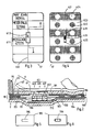
- the telephone dialing arrangement according to FIG. 1 consists of a telephone set 1 and a number of cards 2.
- the telephone set has a number and control keyboard 11, display 12 and storage troughs 13a and 13b for the handset, which is not identified.
- the vertical edge is recessed at a point 16 by one easy to remove inserted card with your finger.
- four membrane keyboard target keys 18 are accommodated; their position is indicated by four crosses "+”.
- the successive three layers of the membrane keyboard are shown in the lower left half of the drawing: the flexible upper layer 181 has a first contact line pattern on its underside; followed by a spacer grid 182 and at the bottom the solid support layer 183 with the mating contact line pattern.
- the remaining electronic circuit 19 is also drawn out downwards; it can be placed anywhere in the telephone set 1. It contains a control unit 191 (Central Processing Unit CPU) and a memory 192 (Memory M), as well as a line and voice unit 193 (L) for connecting the central line a, b and the telephone handset.
- a control unit 191 Central Processing Unit CPU
- a memory 192 Memory M
- L line and voice unit 193
- the card 2 is divided into four equal-sized, writable fields 21 a, b, c, d on its upper side. This division corresponds to the arrangement of the four target buttons 18 according to the four crosses in the recess 15, also recognizable in the contact line patterns of the layers 181 and 183 and the holes in the spacer grid 182.
- This card 2 is so flexible that the top layer passes through it 181 pressed on the base layer 183 and thus the target key contact concerned can be closed.
- the form and lettering of the card 2 can also be attached to the card 2 with the aid of an adhesive film.
- the map 2 was divided into only four fields 21c-d for drawing reasons; in practical application, for example according to the embodiment Fig. 2-6, however, a card of 6x10 cm in size in two columns with six fields 61, i.e. 12 fields divided. With a set of up to seven cards per device, the requirements of most private individuals or households or small companies for their individual directory number with up to 84 names can be met very economically.
- FIGS. 2 to 6 differs in another way from that in FIG. 1.
- the card 6 has a fixed writing medium 61 for the entries of the user and a transparent cover film 62 adhering to it. Furthermore, the identifier of the card 6 is detected by a reflective light barrier arrangement 63, a 3-bit code for the set of seven cards per apparatus mentioned.
- the writing medium 61 consists of white semi-cardboard and, according to FIG. 3, contains a rectangular cutout 613 along the line network 612 printed on to delimit the fields 611, which serves to pass the rays of the light barrier arrangement 63.
- the cover film 62 has, as indicated in FIG. 4, on its upper side an alternating pattern of a light color shade 621, 622, FIG. 4 corresponding to the field division 611 with uncolored areas 623, 624. In a set of cards, seven different color tones can be used for visual differentiation, for example in compartment 14 Fig. 1. 4 has the three-part optical code 625, 626 and 627, in the present case two reflective surfaces 625 and 627 and in between an absorbent black surface 626.
- the adhesive coating is of the type generally known from 3M's POST-IT (TM) sticky notes, and which allows the cover film 62 to be stuck onto the writing medium 61 and removed again several times, e.g. with additions to the directory on card 6, without causing damage. This is indicated in Fig. 2 by the dashed, bent piece 62 'of the cover film 62. Furthermore, the color tint 621, 622 is so weak or transparent that when the card 6 is assembled, the inscriptions on the writing medium 61 are still legible through them.
- TM 3M's POST-IT
- part of the apparatus 1 or 7, which is generally constructed according to FIG. 1, is shown with a card 6 placed on it.
- the rounded edge 75 of the recess (15 in FIG. 1) still appears on the left in FIG.
- the membrane keyboard 78 consists of the top layer 781, the spacer grating 782 and the support layer 783, but with the special feature that the three identical transmitter / receiver units 77 of the reflex light barrier arrangement 63 are also accommodated in it.
- the support plate 751 which is also part of the apparatus housing and by means of which the membrane keyboard 78 is attached to the edge 75 from below, is bulged downward.
- the daylight influence on the transmitter / receiver unit is very limited with two measures. 1. By attaching a daylight filter in front of the receivers, 2. By taking measures to control the transmitter.
- FIG. 5 and 6 show how, by means of a simple punching process, a U-shaped cut 785 is first made in the support layer 783, and then the flap 786 that is formed is bent downwards.
- the base layer 783 is glued to the support plate 751, it then fits well on the latter. Possibly lower transmitter / receiver units that will be available in the future will make the above-mentioned bends unnecessary.
- the transmitter / receiver units 77 are surface-mounted (surface mounted technology) at the solder joints 771 with the line pattern 787, which forms the latter with the opposite line pattern 788 and the film contact 784. Since the upper layer 781 is translucent in any case, it is only necessary to ensure that no conductor tracks of the counter-conductor pattern 788 interfere with the light path. This is indicated in Fig. 2 by omitting the hatching.
- the vertical dimensions are shown greatly enlarged compared to the horizontal;
- the indication that the card 6 and the membrane keyboard 78 - calculated without an offset - are each about 0.7 mm thick. This results in favorable conditions for the required deflection when the target keys are pressed.
- a short tone indicates whether the operation has been carried out correctly.
- the display 12 is used to monitor the process.
- the destination keys can also be arranged to the side of the recess, which means that simple, not particularly flexible cards with optical or other identifiers can be used.
- This identifier can also be affixed to other areas or locations on the card as described; also a color tint. For reasons of space, we do not present such variants in detail.
Landscapes
- Engineering & Computer Science (AREA)
- Signal Processing (AREA)
- Telephone Set Structure (AREA)
- Credit Cards Or The Like (AREA)
Applications Claiming Priority (4)
| Application Number | Priority Date | Filing Date | Title |
|---|---|---|---|
| CH498587 | 1987-12-22 | ||
| CH4985/87 | 1987-12-22 | ||
| CH4455/88 | 1988-12-01 | ||
| CH445588 | 1988-12-01 |
Publications (1)
| Publication Number | Publication Date |
|---|---|
| EP0324316A1 true EP0324316A1 (de) | 1989-07-19 |
Family
ID=25695516
Family Applications (1)
| Application Number | Title | Priority Date | Filing Date |
|---|---|---|---|
| EP88810882A Withdrawn EP0324316A1 (de) | 1987-12-22 | 1988-12-21 | Telefon-Wählanordnung |
Country Status (6)
| Country | Link |
|---|---|
| US (1) | US4914691A (da) |
| EP (1) | EP0324316A1 (da) |
| DK (1) | DK712088A (da) |
| FI (1) | FI885919A7 (da) |
| NO (1) | NO885715L (da) |
| PT (1) | PT89295A (da) |
Cited By (1)
| Publication number | Priority date | Publication date | Assignee | Title |
|---|---|---|---|---|
| EP0413364A3 (en) * | 1989-08-17 | 1992-07-29 | Sharp Kabushiki Kaisha | Dial number generator |
Families Citing this family (14)
| Publication number | Priority date | Publication date | Assignee | Title |
|---|---|---|---|---|
| US5099512A (en) * | 1988-09-22 | 1992-03-24 | Kabushiki Kaisha Toshiba | Communication terminal device |
| US5134717A (en) * | 1988-11-26 | 1992-07-28 | Motorola, Inc. | Radio telephone with repertory dialer |
| US5146493A (en) * | 1989-07-06 | 1992-09-08 | Canon Kabushiki Kaisha | Communication system |
| US5590190A (en) * | 1989-10-31 | 1996-12-31 | Canon Kabushiki Kaisha | Data communication apparatus including volatile and non-volatile storage |
| DE69125741T2 (de) * | 1990-02-20 | 1997-10-02 | Canon Kk | Faksimilegerät |
| US5450078A (en) * | 1992-10-08 | 1995-09-12 | Intellitools, Inc. | Membrane computer keyboard and method |
| US7266186B1 (en) | 1994-01-05 | 2007-09-04 | Intellect Wireless Inc. | Method and apparatus for improved paging receiver and system |
| US6278862B1 (en) | 1994-01-05 | 2001-08-21 | Daniel A. Henderson | Method and apparatus for enhancing the efficient communication of information in an alphanumeric paging network |
| US7426264B1 (en) | 1994-01-05 | 2008-09-16 | Henderson Daniel A | Method and apparatus for improved personal communication devices and systems |
| US6427064B1 (en) | 1994-01-05 | 2002-07-30 | Daniel A. Henderson | Method and apparatus for maintaining a database in a portable communication device |
| US20090244402A1 (en) * | 2006-06-29 | 2009-10-01 | Rye David J | Favorite channel remote |
| US20080001773A1 (en) * | 2006-06-29 | 2008-01-03 | X10 Ltd. | Programmable remote control and methods of using same |
| US20100127912A1 (en) * | 2008-11-26 | 2010-05-27 | X-10 Ltd. | Remote control |
| US10957445B2 (en) | 2017-10-05 | 2021-03-23 | Hill-Rom Services, Inc. | Caregiver and staff information system |
Citations (3)
| Publication number | Priority date | Publication date | Assignee | Title |
|---|---|---|---|---|
| EP0025254A1 (en) * | 1979-08-20 | 1981-03-18 | Suchi Chiou | A telephone set |
| EP0158294A2 (de) * | 1984-04-06 | 1985-10-16 | Bayer Diagnostic GmbH | Telefonanrufbeantworter |
| DE3432270C2 (de) * | 1984-09-01 | 1987-02-19 | Telefonbau Und Normalzeit Gmbh, 6000 Frankfurt | Anordnung zur Mehrfachausnutzung von Bedientasten an Fernmelde-, insbesondere Fernsprech-Endgeräten |
Family Cites Families (6)
| Publication number | Priority date | Publication date | Assignee | Title |
|---|---|---|---|---|
| US4030094A (en) * | 1975-07-14 | 1977-06-14 | Varian Associates | Device for selecting computer operational mode and labeling input controls accordingly |
| US4275273A (en) * | 1979-02-08 | 1981-06-23 | Ts Ao Si Ling | Telephone index for repertory dialer |
| US4595798A (en) * | 1984-01-18 | 1986-06-17 | Marcamor, Inc. | Telephone number input terminal devices |
| US4771557A (en) * | 1985-07-19 | 1988-09-20 | C.R. Gibson Company | Transparent pocket for mounting display items and method for manufacturing same |
| US4741119A (en) * | 1985-12-05 | 1988-05-03 | Baryla Stanley J | Electrostatic display board |
| US4661976A (en) * | 1986-04-21 | 1987-04-28 | Mfb Enterprises, Inc. | Automatic telephone dialer utilizing an electronic telephone book |
-
1988
- 1988-12-21 PT PT89295A patent/PT89295A/pt not_active Application Discontinuation
- 1988-12-21 EP EP88810882A patent/EP0324316A1/de not_active Withdrawn
- 1988-12-21 FI FI885919A patent/FI885919A7/fi not_active Application Discontinuation
- 1988-12-21 DK DK712088A patent/DK712088A/da not_active Application Discontinuation
- 1988-12-21 US US07/287,147 patent/US4914691A/en not_active Expired - Fee Related
- 1988-12-22 NO NO88885715A patent/NO885715L/no unknown
Patent Citations (3)
| Publication number | Priority date | Publication date | Assignee | Title |
|---|---|---|---|---|
| EP0025254A1 (en) * | 1979-08-20 | 1981-03-18 | Suchi Chiou | A telephone set |
| EP0158294A2 (de) * | 1984-04-06 | 1985-10-16 | Bayer Diagnostic GmbH | Telefonanrufbeantworter |
| DE3432270C2 (de) * | 1984-09-01 | 1987-02-19 | Telefonbau Und Normalzeit Gmbh, 6000 Frankfurt | Anordnung zur Mehrfachausnutzung von Bedientasten an Fernmelde-, insbesondere Fernsprech-Endgeräten |
Non-Patent Citations (1)
| Title |
|---|
| BELL LABORATORIES RECORD, Band 59, Nr. 4, April 1981, Seiten 117-122, Murray Hill, New Jersey, US; N.R. HALL et al.: "TOUCH-A-MATIC'S telephone-styled for the residence market" * |
Cited By (2)
| Publication number | Priority date | Publication date | Assignee | Title |
|---|---|---|---|---|
| EP0413364A3 (en) * | 1989-08-17 | 1992-07-29 | Sharp Kabushiki Kaisha | Dial number generator |
| US5185788A (en) * | 1989-08-17 | 1993-02-09 | Sharp Kabushiki Kaisha | Dial number generator |
Also Published As
| Publication number | Publication date |
|---|---|
| DK712088D0 (da) | 1988-12-21 |
| DK712088A (da) | 1989-06-23 |
| NO885715D0 (no) | 1988-12-22 |
| FI885919A7 (fi) | 1989-06-23 |
| NO885715L (no) | 1989-06-23 |
| PT89295A (pt) | 1989-09-14 |
| US4914691A (en) | 1990-04-03 |
Similar Documents
| Publication | Publication Date | Title |
|---|---|---|
| EP0324316A1 (de) | Telefon-Wählanordnung | |
| DE2819713C3 (de) | Hilfstastenfeld | |
| DE3688351T2 (de) | Fernsprecher. | |
| DE3123596C2 (da) | ||
| DE3311032C2 (de) | Anordnung zum selbsttätigen Wählen von Zielnummern | |
| DE2242255A1 (de) | Schluesselfeldplatte | |
| DE2139044C3 (de) | Elektrische Selbstlerneinrichtung | |
| DE3017470A1 (de) | Mehrfachausdruck-dateneingabeeinrichtung | |
| CH658760A5 (de) | Telefon-waehlautomat. | |
| DE2024984A1 (de) | Membran-Schalteinrichtung | |
| DE1815995A1 (de) | Fernsprechwaehlvorrichtung | |
| DE3702509A1 (de) | Verfahren fuer eine mobile elektronische waehlhilfe an fernsprechstationen | |
| DE3335774C2 (da) | ||
| EP0120477A2 (de) | Anordnung zum selbsttätigen Wählen von Zielnummern | |
| DE69027381T2 (de) | Wählnummergenerator | |
| CH666152A5 (de) | Vorrichtung zum speichern und wiedergeben von teilnehmerrufnummern. | |
| DE3410608A1 (de) | Verfahren zur vielfachausnuetzung der tasten der tastatur von einfachen fernsprechstationen | |
| DE3432270C2 (de) | Anordnung zur Mehrfachausnutzung von Bedientasten an Fernmelde-, insbesondere Fernsprech-Endgeräten | |
| DE958660C (de) | Anordnung zur automatischen Wahl von Fernsprechnummern | |
| DE3110863A1 (de) | Bedienungstastatur fuer fernmelde-, insbesondere fernsprechgeraete | |
| DE3037532C2 (de) | Merkblattregister mit einer Vorrichtung zur Durchführung einer Wahl in Fernmelde-, insbesondere Fernsprechanlagen | |
| DE3017469A1 (de) | Mehrfachausdruck-dateneingabeeinrichtung | |
| DE3037472C2 (de) | Merkblattregister mit einer Vorrichtung zur Durchführung einer Wahl in Fernmelde-, insbesondere Fernsprechanlagen | |
| AT234159B (de) | Anordnung zur Durchführung der automatischen Wahl in Fernmelde-, insbesondere Fernsprechanlagen | |
| DE3037510A1 (de) | Merkblattregister mit einer vorrichtung zur durchfuehrung einer wahl in fernmelde-, insbesondere fernsprechanlagen |
Legal Events
| Date | Code | Title | Description |
|---|---|---|---|
| PUAI | Public reference made under article 153(3) epc to a published international application that has entered the european phase |
Free format text: ORIGINAL CODE: 0009012 |
|
| AK | Designated contracting states |
Kind code of ref document: A1 Designated state(s): AT BE CH DE ES FR GB IT LI NL SE |
|
| 17P | Request for examination filed |
Effective date: 19891117 |
|
| 17Q | First examination report despatched |
Effective date: 19911106 |
|
| STAA | Information on the status of an ep patent application or granted ep patent |
Free format text: STATUS: THE APPLICATION IS DEEMED TO BE WITHDRAWN |
|
| 18D | Application deemed to be withdrawn |
Effective date: 19930615 |