EP0324141B1 - Farbwerk - Google Patents
Farbwerk Download PDFInfo
- Publication number
- EP0324141B1 EP0324141B1 EP88121339A EP88121339A EP0324141B1 EP 0324141 B1 EP0324141 B1 EP 0324141B1 EP 88121339 A EP88121339 A EP 88121339A EP 88121339 A EP88121339 A EP 88121339A EP 0324141 B1 EP0324141 B1 EP 0324141B1
- Authority
- EP
- European Patent Office
- Prior art keywords
- chamber
- doctor blade
- ink
- inking unit
- doctor
- Prior art date
- Legal status (The legal status is an assumption and is not a legal conclusion. Google has not performed a legal analysis and makes no representation as to the accuracy of the status listed.)
- Expired - Lifetime
Links
- 238000011144 upstream manufacturing Methods 0.000 claims description 7
- 238000007789 sealing Methods 0.000 claims description 5
- 238000007639 printing Methods 0.000 claims description 3
- 239000002184 metal Substances 0.000 claims 3
- 238000007774 anilox coating Methods 0.000 description 36
- 239000003973 paint Substances 0.000 description 13
- 239000000356 contaminant Substances 0.000 description 3
- 238000011161 development Methods 0.000 description 3
- 230000018109 developmental process Effects 0.000 description 3
- 238000007645 offset printing Methods 0.000 description 3
- 239000000428 dust Substances 0.000 description 2
- 238000003780 insertion Methods 0.000 description 2
- 230000037431 insertion Effects 0.000 description 2
- 239000000919 ceramic Substances 0.000 description 1
- 238000010276 construction Methods 0.000 description 1
- 238000010438 heat treatment Methods 0.000 description 1
- 239000012535 impurity Substances 0.000 description 1
- 239000002245 particle Substances 0.000 description 1
- 230000000149 penetrating effect Effects 0.000 description 1
- 230000000284 resting effect Effects 0.000 description 1
- 230000002441 reversible effect Effects 0.000 description 1
- 230000008961 swelling Effects 0.000 description 1
Images
Classifications
-
- B—PERFORMING OPERATIONS; TRANSPORTING
- B41—PRINTING; LINING MACHINES; TYPEWRITERS; STAMPS
- B41F—PRINTING MACHINES OR PRESSES
- B41F31/00—Inking arrangements or devices
- B41F31/02—Ducts, containers, supply or metering devices
- B41F31/027—Ink rail devices for inking ink rollers
Definitions
- the invention relates to an inking unit, in particular a short inking unit, for printing machines, in particular offset printing machines, with at least one anilox roller, which is assigned a chambered doctor blade arrangement with two doctor blades, which are preferably accommodated on a doctor blade holder and are offset with respect to one another in the circumferential direction of the anilox roller and which delimit an ink chamber which can be acted upon by ink. into which the anilox roller is immersed, as can be seen, for example, from US Pat. No. 4,590,855.
- this object is achieved in that the ink chamber is preceded by an inkable pre-chamber outside of the doctor blade, which acts as a front or closing squeegee and is upstream in the direction of rotation of the anilox roller, and into which the anilox roller is immersed.
- the inking of the anilox roller in the area of the pre-chamber ensures that the entire length of the doctor blade, which is at risk of wear due to the contaminants to be wiped off, is applied over its entire length, which also ensures gentle operation in the event of an unfavorable angle of attack of this doctor blade. With the help of the measures according to the invention, it is therefore possible to ensure a long doctor life even if the doctor blade located upstream is turned negative.
- the prechamber can be supplied with paint from the paint chamber, which can preferably be pressurized, via at least one overflow opening.
- a particularly simple design results in an advantageous manner in that the prechamber is separated from the ink chamber only by the doctor blade located upstream and that at least one overflow opening is provided in the area of this doctor blade and / or its receptacle.
- the prechamber can expediently be provided with a paint overflow, which can be formed in a simple manner in that the prechamber is delimited by a baffle plate which does not touch the anilox roller.
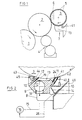
- the short inking unit on which Firgur 1 is based consists of a rubberized applicator roller 2 which cooperates with a plate cylinder 1 which can be covered with hard offset printing plates and which has the same diameter as the plate cylinder and an anilox roller 3 which cooperates with the applicator roller 2 and which has a smaller diameter Applicator roller 2 together with a dampening unit designated as a whole by 4.
- the circumference of the anilox roller 3, which can have a ceramic cover, is provided with cups 5 indicated in an enlarged manner in FIG. 1 and webs 6 delimiting them. The cups 5 are filled with paint, the webs 6 are scraped off, so that there is an exact dosage of the paint corresponding to the capacity of the cups 5.
- FIG. 1 The ink supply to the anilox roller 3 and the doctoring take place by means of a chamber doctor blade arrangement designated as a whole in FIG. 1, which, as can best be seen from FIG. 2, is provided by two in the circumferential direction of the anilox roller 3 doctor blades 11, 12 which are offset from one another and have an ink chamber 13 which is delimited and has an antechamber 41 arranged upstream thereof, that is to say arranged upstream of the ink chamber 13.
- a plurality of chamber doctor blade arrangements 7 arranged next to one another for example two chamber doctor blade arrangements 7 each comprising half a roller length, can be provided.
- the chambered doctor blade arrangement 7 comprises, as can further be seen in FIG. 2, a bar-shaped doctor holder 9 which can be received on supports 8 fixed to the frame and on which the two doctor blades 11, 12 which are offset with respect to one another in the direction of rotation of the anilox roller 3 are accommodated.
- the doctor blades 11, 12 are held by jaws 10.
- the jaws 10 can thus be designed as clamping jaws which clamp the respectively assigned doctor blade on the doctor holder 9.
- the jaws 10 together with the doctor holder 9 are each intended to limit an insertion slot into which the associated doctor blade can be inserted without clamping, that is to say loosely.
- the clear width of the insertion slot is three to four hundredths of a millimeter larger than the thickness of the doctor blade assigned in each case. This ensures that the doctor blades can expand laterally in the event of heating to be feared, particularly when processing offset ink, so that even with low contact force and therefore gentle operation, ripple of the doctor blades is prevented and reliable contact of the doctor blades is achieved.
- both doctor blades 11, 12 lie against the circumference of the anilox roller 3 with a negative angle of attack, that is to say with the circumferential section lying back in the direction of rotation of the anilox roller 3, against the circumference of the anilox roller 3. If the direction of rotation of the anilox roller 3 should be reversible, a symmetrical, roof-shaped doctor blade arrangement could also be provided, with only the doctor blade located downstream in the direction of rotation of the anilox roller 3 being negatively positioned.
- the two doctor blades 11, 12 offset from one another form the rear and front limits of the ink chamber 13 in the direction of rotation of the anilox roller 3, the radial limits of which are formed by the doctor blade holder 9 and the circumference of the anilox roller 3.
- the ink chamber 3 and the pre-chamber 41 are closed on the end face by sealing jaws 43 resting on the end faces of the doctor blades 11, 12.
- the sealing jaws 43 are gripped in the region of their contact with the doctor blades 11, 12 by finger-shaped abutments 44 which extend in the longitudinal direction of the doctor blades 11 , 12 are resiliently supported on the squeegee holder 9, as indicated at 45.
- the ink chamber 13 is supplied with paint.
- the squeegee holder 9 is provided with a distribution chamber 17 formed by an axial bore, from which a plurality of inflow bores 19, which are distributed uniformly over the length of the squeegee holder 9 and exit into the ink chamber 13, and which via a connection bore 18 lead to a supply line leading to an ink pump 16 15 can be connected.
- the ink in the ink chamber 13 should be present with a slight overpressure, so that the anilox roller 3 is reliably inked without further aids.
- the pre-chamber 41 is also supplied with paint.
- the pre-chamber 41 can be provided with its own paint supply.
- the pre-chamber 41 is acted upon by excess paint emerging from the ink chamber 13.
- the ink chamber 13 is in fact provided with overflow openings 24, via which ink can flow, which is returned to the pump 16, so that a color cycle results.
- These overflow openings 24, as can be seen further in FIG. 2, can be designed as bore-shaped recesses, spaced from the doctor edge, of the upstream doctor blade 11, which acts as a preliminary or closing doctor blade.
- slots arranged in the area of the doctor blade holder could also be provided as overflow openings.
- prechamber 41 is applied uniformly over the entire length of the chamber divided overflow openings 24 provided.
- the antechamber 41 is delimited by a dust plate 40 arranged approximately parallel to the adjacent doctor blade 11, which does not touch the circumference of the anilox roller 3.
- the roller-side edge of the baffle plate 40 thus forms an overflow edge delimiting an outlet slot 42.
- the baffle plate 40 can be molded onto the squeegee holder 9 or the closing squeegee jaws 10 or, as here, be attached.
- the ink penetrating through the overflow openings 24 is accumulated in the antechamber 41.
- the excess ink can swell out of the pre-chamber 41 in the area of the outlet gap 42, so that only a complete filling of the pre-chamber 41 is guaranteed, but the occurrence of an undesirable overpressure is not possible.
- the outlet gap 42 is covered by a drainage channel 14 which catches the excess paint dripping off.
- a return line 26 leads from the drainage channel 14 to a paint reservoir or directly to the paint pump 16.
- doctor blade 11 anilox roller receives its final inking in the area of the ink chamber 13, which is under a slight positive pressure here, that is to say the filling of the cells 5 is supplemented where something is still missing.
- the webs 6 are scraped off by means of the doctor blade 12 located downstream. Accordingly, this is known as a squeegee.
- the opposite doctor blade is referred to as the front or closing doctor blade. In the exemplary embodiment shown, both doctor blades 11, 12, as already mentioned above, are made negative.
- a fixed, predetermined direction of rotation of the anilox roller 3 is used, so that only one prechamber 41 is provided which is adjacent to the doctor blade, which acts in each case as a pre-doctor or closing doctor. If the direction of rotation of the anilox roller 3 can be reversed, prechambers could be provided in the area of both doctor blades, with no prechamber not being used in each case by applying a doctor blade with overflow openings only in the region of the prechamber required.
Landscapes
- Inking, Control Or Cleaning Of Printing Machines (AREA)
Applications Claiming Priority (2)
| Application Number | Priority Date | Filing Date | Title |
|---|---|---|---|
| DE3800411 | 1988-01-09 | ||
| DE3800411A DE3800411A1 (de) | 1988-01-09 | 1988-01-09 | Farbwerk |
Publications (3)
| Publication Number | Publication Date |
|---|---|
| EP0324141A2 EP0324141A2 (de) | 1989-07-19 |
| EP0324141A3 EP0324141A3 (en) | 1990-08-22 |
| EP0324141B1 true EP0324141B1 (de) | 1992-07-08 |
Family
ID=6344988
Family Applications (2)
| Application Number | Title | Priority Date | Filing Date |
|---|---|---|---|
| EP88121339A Expired - Lifetime EP0324141B1 (de) | 1988-01-09 | 1988-12-21 | Farbwerk |
| EP88121337A Expired - Lifetime EP0324139B1 (de) | 1988-01-09 | 1988-12-21 | Rakeleinrichtung |
Family Applications After (1)
| Application Number | Title | Priority Date | Filing Date |
|---|---|---|---|
| EP88121337A Expired - Lifetime EP0324139B1 (de) | 1988-01-09 | 1988-12-21 | Rakeleinrichtung |
Country Status (4)
| Country | Link |
|---|---|
| US (2) | US5010815A (enExample) |
| EP (2) | EP0324141B1 (enExample) |
| JP (2) | JPH07102687B2 (enExample) |
| DE (3) | DE3800411A1 (enExample) |
Families Citing this family (21)
| Publication number | Priority date | Publication date | Assignee | Title |
|---|---|---|---|---|
| DE3938447A1 (de) * | 1989-11-18 | 1991-05-23 | Roland Man Druckmasch | Farbwerk mit zonaler dosierung der farbmenge |
| DE4012825A1 (de) * | 1990-04-23 | 1991-10-24 | Koenig & Bauer Ag | Kammerrakel |
| US5213037A (en) * | 1990-11-02 | 1993-05-25 | The Procter & Gamble Company | Apparatus for applying ink to a substrate |
| DE4117390C2 (de) * | 1991-05-28 | 2003-11-06 | Koenig & Bauer Ag | Rakelbalken für ein Farbwerk einer Rotationsdruckmaschine |
| DE4119338A1 (de) * | 1991-06-12 | 1992-12-17 | Koenig & Bauer Ag | Kurzfarbwerk fuer eine offset-rollenrotationsdruckmaschine |
| FR2689451B1 (fr) * | 1992-04-03 | 1997-01-17 | Komori Chambon | Dispositif d'encrage pour un appareil d'impression heliographique. |
| DE4401299C2 (de) * | 1994-01-18 | 1997-04-30 | Roland Man Druckmasch | Vorrichtung zum Einfärben einer Rasterwalze einer Rotationsdruckmaschine |
| US5495800A (en) * | 1995-03-29 | 1996-03-05 | Cavanagh Corporation | Enhanced application printing ink hand proofing device |
| US5836519A (en) * | 1996-10-03 | 1998-11-17 | Brown; Robert S. | Portable wheeled spraying apparatus having an adjustable handle |
| DE29617829U1 (de) * | 1996-10-14 | 1997-01-23 | Voith Sulzer Papiermaschinen GmbH, 89522 Heidenheim | Auftragseinrichtung zum Auftragen eines Streichmediums |
| US6119595A (en) * | 1997-10-06 | 2000-09-19 | R. J. Reynolds Tobacco Company | Gravure printing press with encapsulated ink applicator and method |
| US6076463A (en) * | 1998-03-13 | 2000-06-20 | Heidelberger Druckmaschinen Ag | Ink metering device and method of metering ink |
| CH693305A5 (fr) * | 1999-03-05 | 2003-05-30 | Bobst Sa | Dispositif d'encrage amovible pour une machine d'impression flexographique. |
| US6378426B1 (en) | 2000-05-12 | 2002-04-30 | Harper Companies International | Manually operable proofer for producing sample test printings of inks and coatings |
| DE10158485A1 (de) | 2001-01-12 | 2002-07-18 | Heidelberger Druckmasch Ag | Farbwerk in einer Druckmaschine |
| US7013104B2 (en) * | 2004-03-12 | 2006-03-14 | Lexmark International, Inc. | Toner regulating system having toner regulating member with metallic coating on flexible substrate |
| US7236729B2 (en) * | 2004-07-27 | 2007-06-26 | Lexmark International, Inc. | Electrophotographic toner regulating member with induced strain outside elastic response region |
| DE102005040929B4 (de) * | 2005-07-18 | 2009-06-04 | Windmöller & Hölscher Kg | Farbkammerrakel |
| JP5391559B2 (ja) * | 2008-03-04 | 2014-01-15 | 凸版印刷株式会社 | 印刷機およびそれを用いた印刷物の製造方法 |
| EP3399099A1 (en) * | 2017-05-03 | 2018-11-07 | Oradoc S.r.l. | Rigid and flexible doctor blade holder and system comprising a cylinder and a doctor blade holder |
| GB2576566B (en) * | 2018-08-24 | 2022-12-14 | Edward Rogerson Mark | Improved wiper blade for printer roller |
Family Cites Families (28)
| Publication number | Priority date | Publication date | Assignee | Title |
|---|---|---|---|---|
| US2018193A (en) * | 1931-08-27 | 1935-10-22 | Goss Printing Press Co Ltd | Inking mechanism and method |
| US2177656A (en) * | 1933-06-30 | 1939-10-31 | Harris Seybold Potter Co | Gravure printing press |
| US2151969A (en) * | 1938-06-09 | 1939-03-28 | Standard Process Corp | Inking apparatus and method |
| GB693187A (en) * | 1950-12-22 | 1953-06-24 | Harold Eric Baliol Scott | Improvements in doctors for paper and like machines |
| FR1164098A (fr) * | 1956-01-13 | 1958-10-06 | Vickerys Ltd | Racle perfectionnée pour machine à fabriquer le papier et machines analogues |
| GB800607A (en) * | 1956-01-13 | 1958-08-27 | Harold Eric Baliol Scott | Improvements in or relating to doctors for papermaking and other machines |
| US3339485A (en) * | 1964-06-15 | 1967-09-05 | Bonnierfoeretagen Ab | Adjustable ink supply device in rotary printing presses |
| GB1230020A (enExample) * | 1967-06-30 | 1971-04-28 | ||
| US3759175A (en) * | 1970-03-10 | 1973-09-18 | Strachan & Henshaw Ltd | Dampening apparatus with rotor for projecting spray |
| DE2228685C3 (de) * | 1972-06-13 | 1978-04-06 | Escher Wyss Gmbh, 7980 Ravensburg | Beschichtungsvorrichtung |
| AT345240B (de) * | 1973-02-01 | 1978-09-11 | Zimmer Peter | Rakeleinrichtung fuer das bedrucken von warenbahnen |
| GB1507825A (en) * | 1974-04-08 | 1978-04-19 | Ahlen & Akerlunds Forlags Ab | Method and device for stripping excess ink from a rotating printing roll in rotogravure presses |
| US4009657A (en) * | 1975-02-25 | 1977-03-01 | Scott Paper Company | Apparatus for applying fluid to an intaglio roll for transfer to a soft, absorbent fibrous web |
| DE2538908A1 (de) * | 1975-09-02 | 1977-03-10 | Kaspar Walter Maschinenfabrik | Langzeit-tiefdruckrakel |
| US4455938A (en) * | 1979-05-22 | 1984-06-26 | Graph Tech Inc. | Dampening apparatus for lithographic press |
| DE3043234A1 (de) * | 1980-11-15 | 1982-07-01 | M.A.N.- Roland Druckmaschinen AG, 6050 Offenbach | Farbkasten fuer eine druckmaschine |
| JPS5962152A (ja) * | 1982-09-30 | 1984-04-09 | Osaka Yomiuri Shinbunsha:Kk | 輪転印刷機におけるインキ供給装置 |
| DE110081T1 (de) * | 1982-12-02 | 1984-10-11 | Rockwell International Corp., Pittsburgh, Pa. | Farbverteilbalken. |
| CH663362A5 (de) * | 1984-01-07 | 1987-12-15 | Jagenberg Ag | Vorrichtung zum beschichten von ueber eine stuetzwalze laufenden materialbahnen mit regelbarer auftragsstaerke. |
| FI71081C (fi) * | 1984-05-11 | 1986-11-24 | Waertsilae Oy Ab | Bestrykningsanordning |
| US4590855A (en) * | 1984-06-18 | 1986-05-27 | Printco Industries, Ltd. | Reverse angle doctor blade assembly with stationary end seal |
| DE3427909C2 (de) * | 1984-07-28 | 1987-02-12 | M.A.N.- Roland Druckmaschinen AG, 6050 Offenbach | Farbdosiereinrichtung |
| US4625643A (en) * | 1984-08-09 | 1986-12-02 | Davis William F | Ink dispensing means |
| US4802928A (en) * | 1984-08-13 | 1989-02-07 | Thermo Electron-Web Systems, Inc. | Doctoring apparatus and method employing prestressed doctor blade |
| DE3505598C2 (de) * | 1984-10-30 | 1986-08-14 | Windmöller & Hölscher, 4540 Lengerich | Spülfarbwerk mit geteilter Farbkammerrakel |
| EP0199520A3 (en) * | 1985-04-19 | 1989-02-08 | Vickers Plc | Gravure printing press and method of manufacturing the same |
| EP0278255A3 (en) * | 1987-02-04 | 1990-09-12 | General Electric Company | Solvent-resistant, compatible polyphenylene ether-linear polyester blends |
| DE3704433A1 (de) * | 1987-02-12 | 1988-08-25 | Frankenthal Ag Albert | Kurzfarbwerk |
-
1988
- 1988-01-09 DE DE3800411A patent/DE3800411A1/de active Granted
- 1988-12-21 EP EP88121339A patent/EP0324141B1/de not_active Expired - Lifetime
- 1988-12-21 EP EP88121337A patent/EP0324139B1/de not_active Expired - Lifetime
- 1988-12-21 DE DE8888121339T patent/DE3872693D1/de not_active Expired - Fee Related
- 1988-12-21 DE DE8888121337T patent/DE3872692D1/de not_active Expired - Lifetime
- 1988-12-27 US US07/290,152 patent/US5010815A/en not_active Expired - Fee Related
-
1989
- 1989-01-09 JP JP1002680A patent/JPH07102687B2/ja not_active Expired - Lifetime
- 1989-01-09 JP JP1002679A patent/JPH01222959A/ja active Pending
-
1991
- 1991-02-21 US US07/659,459 patent/US5072669A/en not_active Expired - Fee Related
Also Published As
| Publication number | Publication date |
|---|---|
| EP0324139A3 (en) | 1990-08-08 |
| DE3800411C2 (enExample) | 1990-03-29 |
| EP0324141A2 (de) | 1989-07-19 |
| DE3872693D1 (de) | 1992-08-13 |
| JPH01222959A (ja) | 1989-09-06 |
| DE3872692D1 (de) | 1992-08-13 |
| EP0324139B1 (de) | 1992-07-08 |
| EP0324139A2 (de) | 1989-07-19 |
| US5010815A (en) | 1991-04-30 |
| DE3800411A1 (de) | 1989-07-20 |
| JPH01225555A (ja) | 1989-09-08 |
| EP0324141A3 (en) | 1990-08-22 |
| US5072669A (en) | 1991-12-17 |
| JPH07102687B2 (ja) | 1995-11-08 |
Similar Documents
| Publication | Publication Date | Title |
|---|---|---|
| EP0324141B1 (de) | Farbwerk | |
| EP0458371B1 (de) | Kurzfarbwerk | |
| DE3823340C2 (de) | Kammerrakel für Rotations-Druckmaschinen | |
| DE3117341C2 (de) | Farbwerk | |
| EP0568674B1 (de) | Farbkammerrakel für einen farbübertragenden körper | |
| EP0078444A1 (de) | Farbwerk für Offsetdruckmaschinen | |
| DE4012825C2 (enExample) | ||
| DE8413874U1 (de) | Vorrichtung zum Befeuchten an lithographischen Druckpressen | |
| EP0324140B1 (de) | Farbwerk | |
| DE4213660C2 (de) | Kurzfarbwerk für eine Rollenrotationsdruckmaschine | |
| DE3838546C2 (enExample) | ||
| DE10023935A1 (de) | Kurzfarbwerk einer Rotationsdruckmaschine | |
| DD144155B1 (de) | Feuchtwerk fuer rotations-offsetdruckmaschinen | |
| DE2849096C2 (de) | Feuchtwerk | |
| CH678710A5 (enExample) | ||
| DE3638813C2 (enExample) | ||
| DE8224875U1 (de) | Farbwerk für Offsetdruckmaschinen | |
| DD148607A1 (de) | Farbwerk | |
| DE1240887B (de) | Farbwerk fuer eine Rotationstiefdruckmaschine | |
| DE102005041185B4 (de) | Vorrichtung zum Einfärben einer Walze an einer Rotationsdruckmaschine | |
| DE4340867A1 (de) | Einrichtung zum An- und Abstellen einer Kammerrakel an eine Auftragwalze in Rotationsdruckmaschinen | |
| EP0916490A2 (de) | Farbwerk für eine Rotationsdruckmaschine | |
| DE29823689U1 (de) | Rollenrotationshochdruckmaschine | |
| DE102005041187A1 (de) | Vorrichtung und Verfahren zum Entfärben einer Walze an einer Rotationsdruckmaschine | |
| DE102007003944A1 (de) | Farbwerk in einer Rotationsdruckmaschine |
Legal Events
| Date | Code | Title | Description |
|---|---|---|---|
| PUAI | Public reference made under article 153(3) epc to a published international application that has entered the european phase |
Free format text: ORIGINAL CODE: 0009012 |
|
| AK | Designated contracting states |
Kind code of ref document: A2 Designated state(s): CH DE FR GB IT LI SE |
|
| PUAL | Search report despatched |
Free format text: ORIGINAL CODE: 0009013 |
|
| AK | Designated contracting states |
Kind code of ref document: A3 Designated state(s): CH DE FR GB IT LI SE |
|
| 17P | Request for examination filed |
Effective date: 19901004 |
|
| 17Q | First examination report despatched |
Effective date: 19910429 |
|
| GRAA | (expected) grant |
Free format text: ORIGINAL CODE: 0009210 |
|
| AK | Designated contracting states |
Kind code of ref document: B1 Designated state(s): CH DE FR GB IT LI SE |
|
| ITF | It: translation for a ep patent filed | ||
| GBT | Gb: translation of ep patent filed (gb section 77(6)(a)/1977) | ||
| REF | Corresponds to: |
Ref document number: 3872693 Country of ref document: DE Date of ref document: 19920813 |
|
| PGFP | Annual fee paid to national office [announced via postgrant information from national office to epo] |
Ref country code: GB Payment date: 19921021 Year of fee payment: 5 |
|
| ET | Fr: translation filed | ||
| PGFP | Annual fee paid to national office [announced via postgrant information from national office to epo] |
Ref country code: FR Payment date: 19921119 Year of fee payment: 5 |
|
| PGFP | Annual fee paid to national office [announced via postgrant information from national office to epo] |
Ref country code: CH Payment date: 19921124 Year of fee payment: 5 |
|
| PGFP | Annual fee paid to national office [announced via postgrant information from national office to epo] |
Ref country code: SE Payment date: 19921125 Year of fee payment: 5 |
|
| PGFP | Annual fee paid to national office [announced via postgrant information from national office to epo] |
Ref country code: DE Payment date: 19921211 Year of fee payment: 5 |
|
| PLBE | No opposition filed within time limit |
Free format text: ORIGINAL CODE: 0009261 |
|
| STAA | Information on the status of an ep patent application or granted ep patent |
Free format text: STATUS: NO OPPOSITION FILED WITHIN TIME LIMIT |
|
| 26N | No opposition filed | ||
| PG25 | Lapsed in a contracting state [announced via postgrant information from national office to epo] |
Ref country code: GB Effective date: 19931221 |
|
| PG25 | Lapsed in a contracting state [announced via postgrant information from national office to epo] |
Ref country code: SE Effective date: 19931222 |
|
| PG25 | Lapsed in a contracting state [announced via postgrant information from national office to epo] |
Ref country code: LI Effective date: 19931231 Ref country code: CH Effective date: 19931231 |
|
| GBPC | Gb: european patent ceased through non-payment of renewal fee |
Effective date: 19931221 |
|
| PG25 | Lapsed in a contracting state [announced via postgrant information from national office to epo] |
Ref country code: FR Effective date: 19940831 |
|
| REG | Reference to a national code |
Ref country code: CH Ref legal event code: PL |
|
| PG25 | Lapsed in a contracting state [announced via postgrant information from national office to epo] |
Ref country code: DE Effective date: 19940901 |
|
| REG | Reference to a national code |
Ref country code: FR Ref legal event code: ST |
|
| EUG | Se: european patent has lapsed |
Ref document number: 88121339.1 Effective date: 19940710 |
|
| PG25 | Lapsed in a contracting state [announced via postgrant information from national office to epo] |
Ref country code: IT Free format text: LAPSE BECAUSE OF NON-PAYMENT OF DUE FEES;WARNING: LAPSES OF ITALIAN PATENTS WITH EFFECTIVE DATE BEFORE 2007 MAY HAVE OCCURRED AT ANY TIME BEFORE 2007. THE CORRECT EFFECTIVE DATE MAY BE DIFFERENT FROM THE ONE RECORDED. Effective date: 20051221 |