EP0319673B1 - Vorrichtung zur Steuerung eines mit Dampf betriebenen Gargerätes und Verfahren zum Betreiben eines solchen Gerätes - Google Patents
Vorrichtung zur Steuerung eines mit Dampf betriebenen Gargerätes und Verfahren zum Betreiben eines solchen Gerätes Download PDFInfo
- Publication number
- EP0319673B1 EP0319673B1 EP88116915A EP88116915A EP0319673B1 EP 0319673 B1 EP0319673 B1 EP 0319673B1 EP 88116915 A EP88116915 A EP 88116915A EP 88116915 A EP88116915 A EP 88116915A EP 0319673 B1 EP0319673 B1 EP 0319673B1
- Authority
- EP
- European Patent Office
- Prior art keywords
- steam
- opening
- air
- cooking
- cooking chamber
- Prior art date
- Legal status (The legal status is an assumption and is not a legal conclusion. Google has not performed a legal analysis and makes no representation as to the accuracy of the status listed.)
- Expired - Lifetime
Links
- 238000000034 method Methods 0.000 title claims description 3
- 238000010411 cooking Methods 0.000 claims abstract description 31
- XLYOFNOQVPJJNP-UHFFFAOYSA-N water Substances O XLYOFNOQVPJJNP-UHFFFAOYSA-N 0.000 claims description 7
- 238000001816 cooling Methods 0.000 claims description 4
- 238000007789 sealing Methods 0.000 claims 1
- 230000007704 transition Effects 0.000 claims 1
- 238000010438 heat treatment Methods 0.000 description 4
- 230000006978 adaptation Effects 0.000 description 1
- 238000009833 condensation Methods 0.000 description 1
- 230000005494 condensation Effects 0.000 description 1
- 239000000203 mixture Substances 0.000 description 1
- 229920006395 saturated elastomer Polymers 0.000 description 1
- 238000010025 steaming Methods 0.000 description 1
Images
Classifications
-
- F—MECHANICAL ENGINEERING; LIGHTING; HEATING; WEAPONS; BLASTING
- F24—HEATING; RANGES; VENTILATING
- F24C—DOMESTIC STOVES OR RANGES ; DETAILS OF DOMESTIC STOVES OR RANGES, OF GENERAL APPLICATION
- F24C15/00—Details
- F24C15/32—Arrangements of ducts for hot gases, e.g. in or around baking ovens
- F24C15/322—Arrangements of ducts for hot gases, e.g. in or around baking ovens with forced circulation
- F24C15/327—Arrangements of ducts for hot gases, e.g. in or around baking ovens with forced circulation with air moisturising
-
- A—HUMAN NECESSITIES
- A21—BAKING; EDIBLE DOUGHS
- A21B—BAKERS' OVENS; MACHINES OR EQUIPMENT FOR BAKING
- A21B3/00—Parts or accessories of ovens
- A21B3/04—Air-treatment devices for ovens, e.g. regulating humidity
-
- A—HUMAN NECESSITIES
- A21—BAKING; EDIBLE DOUGHS
- A21C—MACHINES OR EQUIPMENT FOR MAKING OR PROCESSING DOUGHS; HANDLING BAKED ARTICLES MADE FROM DOUGH
- A21C13/00—Provers, i.e. apparatus permitting dough to rise
-
- A—HUMAN NECESSITIES
- A47—FURNITURE; DOMESTIC ARTICLES OR APPLIANCES; COFFEE MILLS; SPICE MILLS; SUCTION CLEANERS IN GENERAL
- A47J—KITCHEN EQUIPMENT; COFFEE MILLS; SPICE MILLS; APPARATUS FOR MAKING BEVERAGES
- A47J27/00—Cooking-vessels
- A47J27/14—Cooking-vessels for use in hotels, restaurants, or canteens
- A47J27/16—Cooking-vessels for use in hotels, restaurants, or canteens heated by steam
-
- F—MECHANICAL ENGINEERING; LIGHTING; HEATING; WEAPONS; BLASTING
- F24—HEATING; RANGES; VENTILATING
- F24C—DOMESTIC STOVES OR RANGES ; DETAILS OF DOMESTIC STOVES OR RANGES, OF GENERAL APPLICATION
- F24C15/00—Details
- F24C15/20—Removing cooking fumes
- F24C15/2007—Removing cooking fumes from oven cavities
Definitions
- the invention relates to a device for controlling a steam-operated cooking device, in particular a baking oven provided with a heated saturated steam generator, and a method for operating such a cooking device. It is known (DE-OS 3443477) to operate a cooking device in addition to the operation with circulated hot air also with steam by supplying steam to the cooking space via a heated steam generator.
- DE-U-8701431 discloses a cooking device with water vapor entering the cooking space, in which the water vapor exiting through an opening in the oven ceiling is conducted via a return line into the negative pressure area of a fan and is discharged via an air duct.
- a problem with such devices consists in controlling the steam generation in such a way that on the one hand the amount of steam in the cooking space is sufficient, but on the other hand the visible steam escape is avoided when the appliance is in operation.
- the invention has for its object to improve such a cooking device so that no disruptive steam escapes when the oven door is opened.
- the claimed control of the various openings enables the steam to be released before it exits so that it no longer interferes with the operation of the device.
- a pot 3 which can be filled with water and which generates 4 steam when heated by, for example, electrical heating elements.
- the steam enters the cooking space, and as soon as the entire muffle is filled with steam, excess steam exits through an opening 5 in the oven ceiling 6.
- a sleeve 8 provided with lateral openings 7, which carries the temperature sensor 9.
- the openings 7 of the sleeve 8 lie in an air duct 10, through which a forced air flow generated by the blower 11 is guided to the front of the device, where it exits above the door 12.
- the forced air flow also influences the steam that initially flows in in small quantities from the outlet opening 5. Only at; only when A sufficiently high excess of steam can therefore influence the temperature sensor in such a way that the heating of the steam generator is reduced or switched off.
- a return line 13 is provided, through which the escaping water vapor is conducted into the negative pressure region of the blower 11, where it is mixed with the other cooling air drawn in by the blower and mixed with it is derived via the air duct 10 which widens towards the front of the device.
- Condensate which forms in the air duct 10, can run through the all-round slope of the air duct 10 to the sleeve and reaches the cooking chamber muffle 2 through the outlet opening 5.
- the condensate baffle 17 guides the condensate to the rear of the door 12 due to its inclination and prevents it so the draining.
- a U-shaped guide wall 14 can be inserted within the air duct 10, which may force steam entering the air duct 10 from the openings 7 into a longer flow path and prevent direct escape to the front of the cooker.
- the steam required to control the steam output and emerging through the opening 5 is in this way sufficiently diluted and cooled, but not the steam still present in the cooking space at the end of the cooking.
- two further openings are provided, which can be closed depending on the program.
- the steam outlet opening 18 with the closure device 20 controlled via 21 opens into the return line 13 and the air supply opening 19 with the closure device 20 controlled via 22 is connected to the pressure channel 24 so that fresh air can flow into the cooking chamber from the pressure channel.
- the device works as follows: The steam outlet opening 18 and the air supply opening 19 with their closure device 20-22 are normally permanently closed. They are only opened in the final phase of steaming. Then steam flows through 18 from the cooking space 2 into the return line 13 of the blower 11. Here, mixing takes place with air, the steam-air mixture flows through the pressure channel 24 and emerges on the front of the appliance, while fresh air flows through 19 from the pressure channel 24 flows. Since the steam generator is switched off in this phase, the steam in the oven muffle is reduced until the program ends, so that hardly any steam escapes when the oven door is opened.
- the opening 5 (Fig. 1 and 3) is always open.
- the control steam flows through them against the steam thermostat. It also prevents the occurrence of any significant overpressure.
- the further opening 23 shown in Fig. 2 is structurally similar to the openings 18 u. 19.
- the vapors are supposed to pass through them escape. It is closed during steam operation, but when the cooking compartment is operated with recirculated hot air or with electr. Resistance heating opened so that the vapors can escape in these operating modes.
Landscapes
- Engineering & Computer Science (AREA)
- Food Science & Technology (AREA)
- Chemical & Material Sciences (AREA)
- Combustion & Propulsion (AREA)
- Mechanical Engineering (AREA)
- General Engineering & Computer Science (AREA)
- Life Sciences & Earth Sciences (AREA)
- Cookers (AREA)
- Commercial Cooking Devices (AREA)
Description
- Die Erfindung betrifft eine Vorrichtung zur Steuerung eines mit Dampf betriebenen Gargerätes, insbesondere eines mit einem beheizten Sattdampferzeuger versehenen Backofens, und ein Verfahren zum Betreiben eines derartigen Gargerätes. Es ist bekannt (DE-OS 3443477) ein Gargerät neben dem Betrieb mit umgewälzter Heißluft auch mit Wasserdampf zu betreiben, indem über einen beheizten Dampferzeuger Wasserdampf dem Garraum zugeführt wird.
- Weiterhin ist durch die DE-U-8701431 ein Gargerät mit in den Garraum eintretenden Wasserdampf bekannt, bei welchem der durch eine öffnung in der Backofendecke austretende Wasserdampf über eine Rückführleitung in den Unterdruckbereich eines Gebläses geleitet und über einen Luftkanal abgeleitet wird Ein Problem bei derartigen Geräten besteht darin, die Dampferzeugung so zu steuern, daß einerseits die Dampfmenge im Garraum ausreicht, andererseits aber der sichtbare Dampfaustritt bei Betrieb des Gerätes vermieden wird. Der Erfindung liegt die Aufgabe zugrunde, ein solches Gargerät so zu verbessern, daß beim öffnen der Backofentür kein störender Dampf austritt.
- Zur Lösung dieser Aufgabe werden die im Patentanspruch 1 angegebenen Merkmale vorgeschlagen.
- Die beanspruchte Steuerung der verschiedenen Öffnungen ermöglicht es den Dampf vor seinem Austritt so abzubauen, daß er nicht mehr bei der Bedienung des Gerätes stört.
- In der Zeichnung ist die Erfindung an einem Ausführungsbeispiel dargestellt. Es zeigen:
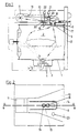
- Fig. 1
- den senkrechten Schnitt durch ein Gargerät
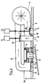
- Fig. 2
- die Draufsicht auf den Luftkanal des Zwangsluftstromes
- Fig. 3
- einen Schnitt durch den Luftkanal des Zwangsluftstromes und des Temperatur-Fühlers entlang der Linie A-A gemäß Fig. 2.
- Im Boden 1 der Garraummuffel 2 ist ein mit Wasser befüllbarer Topf 3 eingelassen, welcher bei Beheizung durch z.B. elektrische Heizelemente 4 Dampf erzeugt. Der Dampf tritt in den Garraum ein, und sobald die gesamte Muffel mit Dampf gefüllt ist, tritt überschüssiger Dampf durch eine Öffnung 5 in der Backofendecke 6 aus. Im Bereich der Auslaßöffnung 5 ist eine mit seitlichen Öffnungen 7 versehene Hülse 8 vorgesehen, welche den Temperaturfühler 9 trägt. Die Öffnungen 7 der Hülse 8 liegen in einem Luftkanal 10, durch welchen ein von dem Gebläse 11 erzeugter Zwangsluftstrom bis zur Vorderseite des Gerätes geführt wird, wo er oberhalb der Tür 12 austritt. Der Zwangsluftstrom beeinflußt auch den aus der Auslaßöffnung 5 zunächst in geringer Menge einströmenden Dampf. Erst bei genügend hohem Dampfüberschuß kann deshalb der Dampf den Temperaturfühler so beeinflussen, daß die Beheizung des Dampferzeugers reduziert oder abgeschaltet wird.
- Sobald durch die reduzierte Beheizung des Dampferzeugers die Dampfmenge absinkt, wird der Dampf bald den Temperaturfühler nicht mehr erreichen. Jetzt sorgt der Zwangsluftstrom für eine schnelle zusätzliche Abkühlung der Hülse 8 und des Fühlers 9. Es wird somit eine schnelle Anpassung an die jeweilige Anforderung erreicht.
- Um die Kondensation des durch die Auslaßöffnung 5 austretenden Wasserdampfes im Bereich der Herdvorderseite zu vermeiden, ist eine Rückführleitung 13 vorgesehen, durch welche der austretende Wasserdampf bis in den Unterdruckbereich des Gebläses 11 geleitet wird und dort mit der übrigen vom Gebläse angesaugten Kühlluft vermischt und mit dieser über den sich zur Gerätevorderseite hin verbreiternden Luftkanal 10 abgeleitet wird.
- Kondensat, das sich im Luftkanal 10 bildet, kann durch das allseitige Gefälle des Luftkanals 10 zur Hülse ablaufen und gelangt durch die Auslaßöffnung 5 wieder in die Garraummuffel 2. Das Kondensat-Leitblech 17 führt aufgrund seiner Neigung das Kondensat zur Rückseite der Tür 12 und verhindert so das Abtropfen.
- Innerhalb des Luftkanals 10 kann eine U-förmige Leitwand 14 eingesetzt sein, welche evtl. aus den öffnungen 7 in den Luftkanal 10 gelangenden Dampf zu einem längeren Strömungsweg zwingt und das direkte Austreten zur Herdvorderseite hin verhindert.
- Der zur Steuerung der Dampfleistung benötigte und durch die Öffnung 5 austretende Dampf wird zwar auf diese Weise ausreichend verdünnt und abgekühlt, nicht aber der im Garraum am Garende noch vorhandene Dampf. Hierzu sind zwei weitere Öffnungen vorgesehen, welche programmabhängig verschließbar sind. Die Dampfaustrittsöffnung 18 mit der über 21 gesteuerten Verschlußeinrichtung 20 mündet in der Rückführungsleitung 13 und die Luftzuführungsöffnung 19 mit der über 22 gesteuerten Verschlußeinrichtung 20 ist an den Druckkanal 24 angeschlossen, so daß Frischluft aus dem Druckkanal in den Garraum einströmen kann.
- Die Wirkungsweise der Vorrichtung ist folgende:
Die Dampfaustrittsöffnung 18 und die Luftzuführungsöffnung 19 mit ihren Verschlußeinrichtung 20-22 sind normalerweise ständig geschlossen. Sie werden lediglich in der Endphase des Dampfgarens geöffnet. Dann strömt Dampf durch 18 aus dem Garraum 2 in die Rückführungsleitung 13 des Gebläses 11. Hier erfolgt die Vermischung mit Luft, das Dampf-Luft-Gemisch strömt durch den Druckkanal 24 und tritt an der Gerätevorderseite aus, während gleichzeitig Frischluft durch 19 aus dem Druckkanal 24 einströmt. Da in dieser Phase der Dampferzeuger abgeschaltet ist, wird bis zum tatsächlichen Programmende der in der Backofenmuffel befindliche Dampf so weit abgebaut, daß beim Öffnen der Backofentür kaum noch Dampf austritt. - Die Öffnung 5 (Fig. 1 u. 3) ist ständig offen. Durch sie strömt der Steuerdampf gegen den Dampfthermostaten. Außerdem verhindert sie das Entstehen eines nennenswerten Überdruckes. Die in Fig. 2 dargestellte weitere Öffnung 23 ist konstruktiv ähnlich aufgebaut wie die Öffnungen 18 u. 19. Durch sie soll der Wrasen entweichen. Sie ist bei Dampfbetrieb geschlossen, aber bei Betrieb des Garraumes mit umgewälzter Heißluft oder bei elektr. Widerstandsbeheizung geöffnet damit der Wrasen bei diesen Betriebsweisen entweichen kann.
Claims (4)
Priority Applications (1)
| Application Number | Priority Date | Filing Date | Title |
|---|---|---|---|
| AT88116915T ATE67581T1 (de) | 1987-12-11 | 1988-10-12 | Vorrichtung zur steuerung eines mit dampf betriebenen gargeraetes und verfahren zum betreiben eines solchen geraetes. |
Applications Claiming Priority (2)
| Application Number | Priority Date | Filing Date | Title |
|---|---|---|---|
| DE3741975 | 1987-12-11 | ||
| DE19873741975 DE3741975A1 (de) | 1987-12-11 | 1987-12-11 | Vorrichtung zur steuerung eines mit dampf betriebenen gargeraetes und vorrichtung zum betreiben eines solchen geraetes |
Publications (2)
| Publication Number | Publication Date |
|---|---|
| EP0319673A1 EP0319673A1 (de) | 1989-06-14 |
| EP0319673B1 true EP0319673B1 (de) | 1991-09-18 |
Family
ID=6342343
Family Applications (1)
| Application Number | Title | Priority Date | Filing Date |
|---|---|---|---|
| EP88116915A Expired - Lifetime EP0319673B1 (de) | 1987-12-11 | 1988-10-12 | Vorrichtung zur Steuerung eines mit Dampf betriebenen Gargerätes und Verfahren zum Betreiben eines solchen Gerätes |
Country Status (3)
| Country | Link |
|---|---|
| EP (1) | EP0319673B1 (de) |
| AT (1) | ATE67581T1 (de) |
| DE (2) | DE3741975A1 (de) |
Cited By (4)
| Publication number | Priority date | Publication date | Assignee | Title |
|---|---|---|---|---|
| FR2688297A1 (fr) * | 1992-03-03 | 1993-09-10 | Europ Equip Menager | Appareil de cuisson electromenager, notamment fours ou cuisinieres comportant un dispositif de mise en depression. |
| FR2797682A1 (fr) | 1999-08-20 | 2001-02-23 | Aeg Hausgeraete Gmbh | Four de cuisson avec phase d'evacuation et procede de fonctionnement d'un tel four de cuisson |
| US6755121B2 (en) | 2000-08-03 | 2004-06-29 | Rational Ag | Cooking chamber with excess pressure and/or low pressure |
| DE102006038415A1 (de) * | 2006-08-17 | 2008-03-27 | BSH Bosch und Siemens Hausgeräte GmbH | Gargerät und Verfahren zum Einstellen einer Dampferzeugung in einem Gargerät |
Families Citing this family (26)
| Publication number | Priority date | Publication date | Assignee | Title |
|---|---|---|---|---|
| FR2705136B1 (fr) * | 1993-05-11 | 1995-06-16 | Cepem | Four de cuisson vapeur à dispositif d'évacuation de la vapeur. |
| DE4341410A1 (de) * | 1993-12-04 | 1995-06-08 | Licentia Gmbh | Back- und Bratofen mit einem Garraum und einem Dampferzeuger für den Garraum |
| ES2116172B1 (es) * | 1994-09-16 | 1999-03-01 | Fagor S Coop | Dispositivo de salida de vapor en horno de cocinado. |
| EP0937400B1 (de) * | 1998-02-13 | 2000-03-29 | eloma GmbH Grossküchentechnik | Verfahren zum umweltschonenden und gefahrlosen Backen oder Garen von Lebensmitteln |
| DE19825322A1 (de) | 1998-06-05 | 1999-12-09 | Bsh Bosch Siemens Hausgeraete | Backofen mit Strömungsleitmitteln |
| FR2817018B1 (fr) * | 2000-11-17 | 2005-09-30 | Brandt Cooking | Dispositif d'evacuation de vapeur d'eau destine a un four de cuisson a la vapeur |
| JP3827679B2 (ja) * | 2003-08-21 | 2006-09-27 | シャープ株式会社 | 加熱調理器 |
| DE102004003409A1 (de) * | 2004-01-23 | 2005-08-18 | Electrolux Schwanden Ag | Multivalent nutzbares Belüftungs-/Kühlungsmodul für Gargeräte mit verschiedenen Garbetriebsarten |
| CH711637B1 (de) | 2004-07-21 | 2017-04-13 | V Zug Ag | Gargerät mit steuerbarer Entlüftung. |
| DE102005003975A1 (de) * | 2005-01-28 | 2006-08-03 | Electrolux Home Products Corp. N.V. | Gargerät |
| ES2371665T3 (es) * | 2005-12-30 | 2012-01-09 | Arcelik A.S. | Horno con sensor. |
| FR2902501B1 (fr) * | 2006-06-15 | 2009-11-27 | Brandt Ind | Four de cuisson a la vapeur |
| FR2902500B1 (fr) * | 2006-06-15 | 2008-08-22 | Brandt Ind Sas | Four de cuisson a la vapeur |
| DE102006047587A1 (de) | 2006-10-05 | 2008-04-10 | Miele & Cie. Kg | Backofen mit einer Backmuffel und einem Querstromlüfter |
| WO2011026819A2 (en) * | 2009-09-01 | 2011-03-10 | Arcelik Anonim Sirketi | An oven whereof heat losses are decreased |
| PL2519776T3 (pl) * | 2009-12-31 | 2016-10-31 | Piekarnik z przewodem wentylacyjnym | |
| DE102010061353A1 (de) * | 2010-12-20 | 2012-06-21 | Miele & Cie. Kg | Gargerät und Verfahren zum Betreiben eines Gargerätes |
| EP2713109B2 (de) | 2012-09-28 | 2020-07-08 | Electrolux Home Products Corporation N.V. | Abgasverschlusssystem für einen Kochherd |
| DE102012222158A1 (de) * | 2012-12-04 | 2014-06-05 | BSH Bosch und Siemens Hausgeräte GmbH | Gargerät |
| DE102013214848A1 (de) * | 2013-07-30 | 2015-02-05 | BSH Bosch und Siemens Hausgeräte GmbH | Backofen mit Feuchtigkeitssensor und Luftmanagementsystem |
| EP3029382B1 (de) | 2014-12-01 | 2018-11-28 | Electrolux Appliances Aktiebolag | Küchengerät umfassend ein feuchtigkeitsspülsystem |
| CN108139079B (zh) * | 2015-10-22 | 2020-05-19 | 伊莱克斯家用电器股份公司 | 用于控制湿度的方法和家用器具 |
| DE102016215650A1 (de) | 2016-08-19 | 2018-02-22 | BSH Hausgeräte GmbH | Haushaltsgargerät |
| TR201612515A2 (tr) * | 2016-09-02 | 2018-03-21 | Arcelik As | Kontrollü egzoz si̇stemi̇ne sahi̇p bi̇r firin |
| DE102018209581A1 (de) | 2018-06-14 | 2019-12-19 | BSH Hausgeräte GmbH | Gargerät |
| US11339974B2 (en) | 2019-03-21 | 2022-05-24 | Bsh Home Appliances Corporation | Multifunctional steam cooking appliance with active air inlet |
Family Cites Families (4)
| Publication number | Priority date | Publication date | Assignee | Title |
|---|---|---|---|---|
| DE3027566C2 (de) * | 1980-07-21 | 1983-03-17 | Bosch-Siemens Hausgeräte GmbH, 7000 Stuttgart | Backofen mit einem Wrasenaustrittskanal |
| FR2559241B1 (fr) * | 1984-02-06 | 1986-12-12 | Dietrich Sa | Perfectionnement permettant la mise et le maintien en depression du moufle d'un four electrodomestique a reacteur catalytique |
| DE8701431U1 (de) * | 1987-01-30 | 1987-03-19 | Buderus Ag, 6330 Wetzlar | Gerät zum Garen von Speisen mittels Wasserdampf |
| DE3703539A1 (de) * | 1987-02-06 | 1988-08-18 | Buderus Kuechentechnik | Vorrichtung zur steuerung der dampfleistung eines mit dampf betriebenen gargeraetes |
-
1987
- 1987-12-11 DE DE19873741975 patent/DE3741975A1/de not_active Withdrawn
-
1988
- 1988-10-12 DE DE8888116915T patent/DE3864986D1/de not_active Expired - Fee Related
- 1988-10-12 AT AT88116915T patent/ATE67581T1/de not_active IP Right Cessation
- 1988-10-12 EP EP88116915A patent/EP0319673B1/de not_active Expired - Lifetime
Cited By (5)
| Publication number | Priority date | Publication date | Assignee | Title |
|---|---|---|---|---|
| FR2688297A1 (fr) * | 1992-03-03 | 1993-09-10 | Europ Equip Menager | Appareil de cuisson electromenager, notamment fours ou cuisinieres comportant un dispositif de mise en depression. |
| EP0615097A1 (de) * | 1992-03-03 | 1994-09-14 | Compagnie Europeenne Pour L'equipement Menager "Cepem" | Elektrisches Haushaltskochgerät wie Ofen, Kochherd oder dergleichen |
| FR2797682A1 (fr) | 1999-08-20 | 2001-02-23 | Aeg Hausgeraete Gmbh | Four de cuisson avec phase d'evacuation et procede de fonctionnement d'un tel four de cuisson |
| US6755121B2 (en) | 2000-08-03 | 2004-06-29 | Rational Ag | Cooking chamber with excess pressure and/or low pressure |
| DE102006038415A1 (de) * | 2006-08-17 | 2008-03-27 | BSH Bosch und Siemens Hausgeräte GmbH | Gargerät und Verfahren zum Einstellen einer Dampferzeugung in einem Gargerät |
Also Published As
| Publication number | Publication date |
|---|---|
| DE3741975A1 (de) | 1989-06-22 |
| EP0319673A1 (de) | 1989-06-14 |
| ATE67581T1 (de) | 1991-10-15 |
| DE3864986D1 (de) | 1991-10-24 |
Similar Documents
| Publication | Publication Date | Title |
|---|---|---|
| EP0319673B1 (de) | Vorrichtung zur Steuerung eines mit Dampf betriebenen Gargerätes und Verfahren zum Betreiben eines solchen Gerätes | |
| DE69409916T2 (de) | Dampfsteuereinrichtung eines Backofens | |
| EP0279065B1 (de) | Vorrichtung zur Steuerung der Dampfleistung eines mit Dampf betriebenen Gargerätes | |
| EP0386862B1 (de) | Gargerät | |
| DE3839657C2 (de) | Luftführungssystem für einen Backofen | |
| DE60121245T2 (de) | Dampferzeugungsmechanismus im Feld von Kochgefässen | |
| DE4423557C2 (de) | Ofen zur Wärmebehandlung von Lebensmitteln | |
| DE69211611T2 (de) | Kochgerät | |
| DE19939673B4 (de) | Garofen mit Auslaßphase | |
| DE2731191B1 (de) | Vorrichtung zur Waermebehandlung von Nahrungsmitteln mittels eines Dampf-Luft-Gemisches | |
| DE3519423A1 (de) | Gargeraet mit verschliessbarem garraum | |
| DE19509569A1 (de) | Ofen zur Wärmebehandlung von Lebensmitteln und Verfahren zum Backen | |
| EP1385382A2 (de) | Backofen | |
| EP0768055B1 (de) | Backofen zum Dampfgaren | |
| DE3246333C2 (de) | ||
| EP0671591A1 (de) | Vorrichtung zum Abführen von Wrasen aus einem Backofen | |
| CH630240A5 (en) | Hot-air circulating, baking, frying and grilling oven, and method of operating it | |
| EP0845234B2 (de) | Vorrichtung und Verfahren zur Regelung des Feuchtigkeitsgehaltes in einer Kochvorrichtung | |
| DE60116849T2 (de) | Dampfauslass für Dampfkochgeräte | |
| DE10037905C2 (de) | Garraum mit Über- und/oder Unterdruck | |
| DE102004003409A1 (de) | Multivalent nutzbares Belüftungs-/Kühlungsmodul für Gargeräte mit verschiedenen Garbetriebsarten | |
| DE2741917C3 (de) | Einbaubratofen | |
| DE19858134A1 (de) | Gargerät und Verfahren zur Wärmebehandlung eines Gargutes mit Dampf | |
| DE29914472U1 (de) | Garofen mit Außengebläse zum Gasauslaß | |
| DE3130064A1 (de) | Backofen |
Legal Events
| Date | Code | Title | Description |
|---|---|---|---|
| PUAI | Public reference made under article 153(3) epc to a published international application that has entered the european phase |
Free format text: ORIGINAL CODE: 0009012 |
|
| AK | Designated contracting states |
Kind code of ref document: A1 Designated state(s): AT CH DE FR GB IT LI NL SE |
|
| 17P | Request for examination filed |
Effective date: 19890620 |
|
| 17Q | First examination report despatched |
Effective date: 19900404 |
|
| GRAA | (expected) grant |
Free format text: ORIGINAL CODE: 0009210 |
|
| RAP1 | Party data changed (applicant data changed or rights of an application transferred) |
Owner name: ELECTROLUX-JUNO KUECHENTECHNIK GMBH |
|
| AK | Designated contracting states |
Kind code of ref document: B1 Designated state(s): AT CH DE FR GB IT LI NL SE |
|
| REF | Corresponds to: |
Ref document number: 67581 Country of ref document: AT Date of ref document: 19911015 Kind code of ref document: T |
|
| REF | Corresponds to: |
Ref document number: 3864986 Country of ref document: DE Date of ref document: 19911024 |
|
| ITF | It: translation for a ep patent filed | ||
| PGFP | Annual fee paid to national office [announced via postgrant information from national office to epo] |
Ref country code: NL Payment date: 19911031 Year of fee payment: 4 |
|
| PGFP | Annual fee paid to national office [announced via postgrant information from national office to epo] |
Ref country code: SE Payment date: 19911108 Year of fee payment: 4 |
|
| GBT | Gb: translation of ep patent filed (gb section 77(6)(a)/1977) | ||
| ET | Fr: translation filed | ||
| PLBE | No opposition filed within time limit |
Free format text: ORIGINAL CODE: 0009261 |
|
| STAA | Information on the status of an ep patent application or granted ep patent |
Free format text: STATUS: NO OPPOSITION FILED WITHIN TIME LIMIT |
|
| 26N | No opposition filed | ||
| PG25 | Lapsed in a contracting state [announced via postgrant information from national office to epo] |
Ref country code: SE Effective date: 19921013 |
|
| PG25 | Lapsed in a contracting state [announced via postgrant information from national office to epo] |
Ref country code: NL Effective date: 19930501 |
|
| NLV4 | Nl: lapsed or anulled due to non-payment of the annual fee | ||
| PGFP | Annual fee paid to national office [announced via postgrant information from national office to epo] |
Ref country code: FR Payment date: 19941017 Year of fee payment: 7 |
|
| PGFP | Annual fee paid to national office [announced via postgrant information from national office to epo] |
Ref country code: GB Payment date: 19941223 Year of fee payment: 7 |
|
| EUG | Se: european patent has lapsed |
Ref document number: 88116915.5 Effective date: 19930510 |
|
| PG25 | Lapsed in a contracting state [announced via postgrant information from national office to epo] |
Ref country code: GB Effective date: 19951012 |
|
| GBPC | Gb: european patent ceased through non-payment of renewal fee |
Effective date: 19951012 |
|
| PG25 | Lapsed in a contracting state [announced via postgrant information from national office to epo] |
Ref country code: FR Effective date: 19960628 |
|
| REG | Reference to a national code |
Ref country code: FR Ref legal event code: ST |
|
| PGFP | Annual fee paid to national office [announced via postgrant information from national office to epo] |
Ref country code: AT Payment date: 19981222 Year of fee payment: 11 |
|
| PG25 | Lapsed in a contracting state [announced via postgrant information from national office to epo] |
Ref country code: AT Free format text: LAPSE BECAUSE OF NON-PAYMENT OF DUE FEES Effective date: 19991012 |
|
| PGFP | Annual fee paid to national office [announced via postgrant information from national office to epo] |
Ref country code: DE Payment date: 19991116 Year of fee payment: 12 Ref country code: CH Payment date: 19991116 Year of fee payment: 12 |
|
| PG25 | Lapsed in a contracting state [announced via postgrant information from national office to epo] |
Ref country code: LI Free format text: LAPSE BECAUSE OF NON-PAYMENT OF DUE FEES Effective date: 20001031 Ref country code: CH Free format text: LAPSE BECAUSE OF NON-PAYMENT OF DUE FEES Effective date: 20001031 |
|
| REG | Reference to a national code |
Ref country code: CH Ref legal event code: PL |
|
| PG25 | Lapsed in a contracting state [announced via postgrant information from national office to epo] |
Ref country code: DE Free format text: LAPSE BECAUSE OF NON-PAYMENT OF DUE FEES Effective date: 20010703 |
|
| PG25 | Lapsed in a contracting state [announced via postgrant information from national office to epo] |
Ref country code: IT Free format text: LAPSE BECAUSE OF NON-PAYMENT OF DUE FEES Effective date: 20051012 |