EP0318721B1 - Système de suspension à réglage actif avec un contrôle de l'alimentation en puissance - Google Patents
Système de suspension à réglage actif avec un contrôle de l'alimentation en puissance Download PDFInfo
- Publication number
- EP0318721B1 EP0318721B1 EP88118441A EP88118441A EP0318721B1 EP 0318721 B1 EP0318721 B1 EP 0318721B1 EP 88118441 A EP88118441 A EP 88118441A EP 88118441 A EP88118441 A EP 88118441A EP 0318721 B1 EP0318721 B1 EP 0318721B1
- Authority
- EP
- European Patent Office
- Prior art keywords
- pressure
- valve
- control
- working chamber
- vehicle body
- Prior art date
- Legal status (The legal status is an assumption and is not a legal conclusion. Google has not performed a legal analysis and makes no representation as to the accuracy of the status listed.)
- Expired - Lifetime
Links
Images


Classifications
-
- B—PERFORMING OPERATIONS; TRANSPORTING
- B60—VEHICLES IN GENERAL
- B60G—VEHICLE SUSPENSION ARRANGEMENTS
- B60G17/00—Resilient suspensions having means for adjusting the spring or vibration-damper characteristics, for regulating the distance between a supporting surface and a sprung part of vehicle or for locking suspension during use to meet varying vehicular or surface conditions, e.g. due to speed or load
- B60G17/015—Resilient suspensions having means for adjusting the spring or vibration-damper characteristics, for regulating the distance between a supporting surface and a sprung part of vehicle or for locking suspension during use to meet varying vehicular or surface conditions, e.g. due to speed or load the regulating means comprising electric or electronic elements
- B60G17/017—Resilient suspensions having means for adjusting the spring or vibration-damper characteristics, for regulating the distance between a supporting surface and a sprung part of vehicle or for locking suspension during use to meet varying vehicular or surface conditions, e.g. due to speed or load the regulating means comprising electric or electronic elements characterised by their use when the vehicle is stationary, e.g. during loading, engine start-up or switch-off
-
- B—PERFORMING OPERATIONS; TRANSPORTING
- B60—VEHICLES IN GENERAL
- B60G—VEHICLE SUSPENSION ARRANGEMENTS
- B60G2400/00—Indexing codes relating to detected, measured or calculated conditions or factors
- B60G2400/10—Acceleration; Deceleration
- B60G2400/102—Acceleration; Deceleration vertical
-
- B—PERFORMING OPERATIONS; TRANSPORTING
- B60—VEHICLES IN GENERAL
- B60G—VEHICLE SUSPENSION ARRANGEMENTS
- B60G2400/00—Indexing codes relating to detected, measured or calculated conditions or factors
- B60G2400/10—Acceleration; Deceleration
- B60G2400/104—Acceleration; Deceleration lateral or transversal with regard to vehicle
-
- B—PERFORMING OPERATIONS; TRANSPORTING
- B60—VEHICLES IN GENERAL
- B60G—VEHICLE SUSPENSION ARRANGEMENTS
- B60G2400/00—Indexing codes relating to detected, measured or calculated conditions or factors
- B60G2400/10—Acceleration; Deceleration
- B60G2400/106—Acceleration; Deceleration longitudinal with regard to vehicle, e.g. braking
-
- B—PERFORMING OPERATIONS; TRANSPORTING
- B60—VEHICLES IN GENERAL
- B60G—VEHICLE SUSPENSION ARRANGEMENTS
- B60G2400/00—Indexing codes relating to detected, measured or calculated conditions or factors
- B60G2400/25—Stroke; Height; Displacement
- B60G2400/252—Stroke; Height; Displacement vertical
-
- B—PERFORMING OPERATIONS; TRANSPORTING
- B60—VEHICLES IN GENERAL
- B60G—VEHICLE SUSPENSION ARRANGEMENTS
- B60G2400/00—Indexing codes relating to detected, measured or calculated conditions or factors
- B60G2400/30—Propulsion unit conditions
-
- B—PERFORMING OPERATIONS; TRANSPORTING
- B60—VEHICLES IN GENERAL
- B60G—VEHICLE SUSPENSION ARRANGEMENTS
- B60G2500/00—Indexing codes relating to the regulated action or device
- B60G2500/30—Height or ground clearance
-
- B—PERFORMING OPERATIONS; TRANSPORTING
- B60—VEHICLES IN GENERAL
- B60G—VEHICLE SUSPENSION ARRANGEMENTS
- B60G2600/00—Indexing codes relating to particular elements, systems or processes used on suspension systems or suspension control systems
- B60G2600/02—Retarders, delaying means, dead zones, threshold values, cut-off frequency, timer interruption
-
- B—PERFORMING OPERATIONS; TRANSPORTING
- B60—VEHICLES IN GENERAL
- B60G—VEHICLE SUSPENSION ARRANGEMENTS
- B60G2600/00—Indexing codes relating to particular elements, systems or processes used on suspension systems or suspension control systems
- B60G2600/22—Magnetic elements
- B60G2600/26—Electromagnets; Solenoids
-
- B—PERFORMING OPERATIONS; TRANSPORTING
- B60—VEHICLES IN GENERAL
- B60G—VEHICLE SUSPENSION ARRANGEMENTS
- B60G2600/00—Indexing codes relating to particular elements, systems or processes used on suspension systems or suspension control systems
- B60G2600/72—Cooling or warming means
-
- B—PERFORMING OPERATIONS; TRANSPORTING
- B60—VEHICLES IN GENERAL
- B60G—VEHICLE SUSPENSION ARRANGEMENTS
- B60G2800/00—Indexing codes relating to the type of movement or to the condition of the vehicle and to the end result to be achieved by the control action
- B60G2800/20—Stationary vehicle
Definitions
- the present invention relates to a control system for controlling suspension characteristics in an automotive suspension system, comprising: a cylinder disposed between a vehicle body and a suspension member which rotatably supports a road wheel, said cylinder defining a variable pressure working chamber filled with a pressure medium for generating a damping force resisting against relative displacement between said vehicle body and said suspension member; a pressure source circuit means connected to said working chamber via a control line for supplying pressure medium and including a pressure source unit feeding pressurized pressure medium through said pressure source circuit means; a pressure control valve connected to said pressure source unit via a supply line and a drain line and to said working chamber via said control line and variable of valve position between a first mode for increasing pressure of said pressure medium within said working chamber, a second mode for decreasing pressure in said pressure medium within said working chamber, and a third mode for maintaining said pressure in said pressure medium within said working chamber constant; a sensor means for monitoring vehicle body attitude change for producing a vehicle body attitude change indicative sensor signal; a controller means for deriving a control signal on the basis
- Actively controlled suspension systems gains popularity in automotive vehicles because of remarkable performance in achieving both of driving stability and riding comfort.
- Such suspension systems performs various control, such as anti-rolling and/or anti-pitching control, bounding suppressive control and so forth, for regulating vehicular body attitude at various vehicle driving mode condition.
- bouncing suppressive suspension control is performed for suppressing relative displacement between a vehicle body and a suspension member which rotatable support a road wheel.
- Relative displacement between the vehicle body and a suspension member is monitored by means a sensor, such as a vertical acceleration sensor, a stroke sensor and so forth.
- US-A-4 349 077 shows a control system corresponding to the preamble of claim 1.
- This document discloses an electric vehicle-level control device, with is provided for controlling an electrically operated fluid pressure control device for a pneumatic, hydraulic or hydropneumatic suspension unit such as a hydropneumatic suspension strut of a self-levelling suspension system for an automotive vehicle.
- the control device comprises a timing or delay circuit adapted to deliver an output signal at a predetermined retarded timing following generation of a signal responsive to a vehicle level higher or lower than a predetermined value, or a signal responsive to shutdown of a power plant such as an internal combustion engine of an automotive vehicle.
- GB-A-2 159 107 shows a vehicle suspension apparatus, in which front and rear wheel suspension units respectively have fluid spring chambers. Fluid is supplied to predermined fluid spring chambers from a fluid source through a supply control valve, and at the same time fluid is exhausted from remaining fluid spring chambers through an exhaust control valve. Three-directional valves are inserted between the respective spring chambers and the exhaust control valve. One end of a front wheel communication path is connected to the front left wheel three-directional valve and the other end of the path is connected to the front right wheel three-directional valve. Similarly, one end of a rear wheel communication path is connected to the rear left wheel three-directional valve and the other end of the path is connected to the rear right wheel three-directional valve.
- the fluid passing through the supply control valve is supplied to the front wheel spring chambers through the front wheel communication path or to the rear wheel spring chambers through the rear wheel communication path.
- Each of the three-directional valves can take the first position where the spring chambers communicate with the supply control valve or the second position where the air spring chambers communicate with the exhaust control valve.
- Another object of the invention is to provide a suspension control system, in which a pressure in a working chamber of a dydraulic cylinder disposed between a vehicular body and a suspension member, is maintained at a preset neutral pressure while power is not supplied to a control unit.
- control system comprises a check valve means provided in said supply line and arranged to allow flow of pressure medium from said pressure source to said pressure control valve, and a shut-off valve means provided in said drain line and responsive to a pilot pressure signal indicative of the pressure in said supply line, whereby the shut-off valve is only maintained in the open position as long as the pilot pressure is equal to or greater than a preset pressure
- said controller means has two operating modes: a normal mode for deriving said control signal on the basis of a value of said vehicle body attitude change indicative signal for supressing vehicular attitude change and a power OFF transition mode, in which the pressure in said working chamber is adjusted toward said preset pressure.
- the power main switch may be an ignition switch.
- the controller means may be variable of operation mode between a normal mode for deriving the control signal on the basis of the vehicular attitude indicative signal value for suppressing vehicular attitude change and a power OFF transition mode, in which pressure of the pressure medium is adjusted toward a preset pressure.
- the controller means may derive the control signal in the power OFF transisition mode for gradually adjusting the pressure of the pressure medium in the working chamber toward a preset pressure.
- the controller means may derive the control signal in the power OFF transisition mode for adjusting the pressure of the pressure medium in the working chamber in stepwise fashion toward the the preset pressure.
- the preferred embodiment of an actively controlled suspension system is designed to generally perform suspension control for suppressing relative displacement between a vehicle body 10 and suspension members 24FL, 24FR, 24RL and 24RR provided in front-left, front-right, rear-left and rear-right suspension mechanisms 14FL, 14FR, 14RL and 14RR and rotatably supporting front-left, front-right, rear-left and rear-right wheels 11FL, 11FR, 11RL and 11RR, which suspension member will be represented by the reference numeral "24" as generally referred to, and suspension mechanisms will be represented by the reference numeral "14" as generally referred to, and whereby suppressing vehicle body attitude change.
- Respective front-left, front-right, rear-left and rear-right suspension mechanisms 14FL, 14FR, 14RL and 14RR include hydraulic cylinders 26FL, 26FR, 26RL and 26RR, which hydraulic cylinder will be hereafter represented by the reference numeral "26" as generally referred to.
- Each of the hydraulic cylinder 26 is disposed between the vehicle body 10 and the suspension member 24 to produce a damping force for suppressing relative displacement between the vehicle body and the suspension member.
- the hydraulic cylinder 26 has a cylinder body 26a.
- the cylinder body 26a defines a working fluid chamber therein.
- a piston 26c is disposed within the working fluid chamber to divide the working fluid chamber into a lower working chamber 26d and an upper reference pressure chamber 26e. As will be seen from Fig. 1, the working chamber 26d and the reference pressure chamber 26e are communicated each other via an orifice 26f defined through the piston 26c.
- the piston 26c is connected to the vehicle body 10 via a piston rod 26b.
- a suspension coil spring 36 is wound around the piston road 26b.
- each hydraulic cylinder 26 is connected to a hydraulic pressure source unit 16 via a pressure supply line 52, a pressure drain line 54, a pressure control valve units 28FL, 28FR, 28RL and 28RR and a pressure control line 38, which pressure control valve units will be hereafter represented by the reference numeral "28" as generally referred to, and a pressure line 38.
- the pressure line 38 is connected to a fluid path 26g defined through the piston rod 26b and the piston 26c.
- the working chamber 26d of the hydraulic cylinder 26 is further communicated with a pressure accumulator 34 via an orifice 32 .
- Another pressure accumulators 18 are provided in the pressure supply line 52 for accumulating the excessive pressure generated by the pressure source unit 16 .
- the pressure control valve unit 28 comprises a proportioning valve and is designed to be controlled by an electric control signal for varying valve position according to variation of current value of the control signal. Generally, the pressure control valve unit 28 controls magnitude of introduction and draining of the pressurized working fluid into and from the working chamber 26d for adjusting the pressure in the working chamber for setting the damping mode of the hydraulic cylinder 26 . To control the valve position of the pressure control valve unit 28 , a control unit 22 which comprises a microprocessor, is provided.
- the control unit 22 is connected to various sensors which monitor vehicle body attitude change representative parameters to produce sensor signals.
- the sensors may include vehicular height sensor 21 for monitoring stroke of relative motion between the vehicle body and the suspension member 24 to produce a vehicle height indicative sensor signal. While the shown embodiment employs the vehicle height sensor as the vehicular attitude change indicative paramter, the similar vehicular height indicative parameter can be monitored by a vertical acceleration sensor which monitors vertical acceleration exerted to the vehicle body to produce vertical acceleration indicative signal for bouncing control for suppressing bounding and rebounding motion of the vehicle body.
- a longitudinal acceleration sensor for monitoring longituginal acceleration exerted on the vehicle body as vehicular pitching representative parameter and a lateral acceleration sensor for monitoring lateral acceleration exerted on the vehicle body a vehicular rolling representative parameter may be employed for anti-pitching and anti-rolling control.
- other sensors such as a vehicular speed sensor, steering angle sensor and so forth which monitor vehicular driving condition affecting vehicular attitude may also be employed for performing various suspension control.
- Fig. 2 shows the detailed construction of the pressure control valve unit 28 to be employed in the shown embodiment of the actively controlled suspension system set forth above.
- the pressure control valve 28 comprises a valve housing 42 which housing a proportioning solenoid 43 .
- the proportioning solenoid 43 is electrically connected to the control unit 22 .
- the valve housing 42 defines a valve bore which is separated into a valve chamber 42L and a control chamber 42U by means of a partitioning member 42A .
- the partitioning member 42A is formed with a communication hole 42a .
- Above the communication hole 42a is defined the control chamber 42U .
- the valve chamber 42L and the control chamber 42U are aligned to each other across the communication hole 42a .
- Beneath the communication hole 42a and adjacent the top of the valve chamber 42L a stationary throttling orifice defining member 44 is provided.
- the throttling orifice defining member 44 is formed with a fixed throttling rate of orifice.
- the throttling orifice defining member 44 defines with the partitioning member 42A a pilot chamber P .
- a valve spool 48 is thrustingly or slidingly disposed within the valve chamber 42L .
- the valve spool 48 defines an upper feedback chamber FU between the top end thereof and the throttling orifice defining member 44 .
- the valve spool 48 also defines a lower feedback chamber FL between the lower end thereof and the bottom of the valve chamber 42L .
- Offset springs 50A and 50B are disposed within the upper and lower feedback chambers FU and FL , which offset springs exerts spring force to the valve spool 48 for resiliently restricting movement of the latter.
- the valve chamber 42L is communicated with an inlet port 42i , a drain port 42o and the communication port 42n which are defined through the valve housing 42 .
- the inlet port 42i is connected to the pressure unit 16 via a supply line 52 .
- the drain port 42o is connected to the pressure unit 16 via the drain line 54 .
- the valve spool 48 is formed with an upper land 48b and a lower land 48a .
- the upper and lower lands 48b and 48a defines therebetween an annular pressure chamber 48c .
- the valve spool 48 is formed with a pilot path communicating the pressure chamber 48c with the lower feedback chamber FL .
- a poppet valve member 56 is disposed within the control chamber 42U for thrusting or sliding movement therein.
- the poppet valve member 56 has a valve head opposing to the communication hole 42a .
- the poppet valve member 56 is operably associated with the proportioning solenoid 43 which comprises a plunger 58 which has a plunger rod 58A .
- the lower end of the plunger rod 58A of the plunger 58 opposes to the top end of the poppet valve member 56 .
- the poppet valve member 56 is driven by the plunger 58 to control the path area in the communication hole 42a according to the position of the plunger rod 58A . Therefore, the poppet valve member 56 adjusts the path area of the communication hole 42a and whereby to control fluid pressure to be introduced in the pilot chamber P .
- the poppet valve member 56 separates the control chamber 42U into upper and lower control chambers.
- a solenoid coil 60 is provided for energizing the deenergizing to cause axial shift of the plunger rod 58A.
- the pressure in the upper feedback chamber FU is adjusted to exert an axially driving force to the valve spool 48 to cause axial shift.
- selective fluid communication between the inlet port 42i, the drain port 42o and the communication port 42n can be established to adjust the fluid pressure at the communication port 42n. Since the pressure at the communication port 42n is equal to the fluid pressure in the woking chamber 26d of the pressure cylinder 26, the damping force created by the pressure cylinder can be adjusted.
- the inlet port 42i is also connected to the pilot chamber P via a fluid path 42s.
- the drain port 42o is connected to control chamber 42U via a fluid path 42t.
- a control current I is applied to the solenoid coil 60.
- Fig. 3 shows alternative embodiment of the pressure control valve unit 28 to be employed in the preferred embodiment of the actively controlled suspension system, according to the invention.
- Fig. 3 shows the detailed construction of the hydraulic cylinder 115A and the pressure control valve 22.
- the hollow cylinder housing 115a is formed with a port 115f communicating the upper fluid chamber 15d to an outlet port 118d of the pressure control valve 22 via a communication line 127.
- the lower fluid chamber 115e is defined as an enclosed space and is filled with the viscous working fluid. The pressure of the working fluid in the lower fluid chamber 115e at an initial position of the piston 115c serves as a reference pressure and per se serves as resistance for downward movement of the piston.
- the pressure control valve 22 has a valve housing 18A having the aforementioned outlet port 118d, an inlet port 118b and a drain port 118c. Respective inlet port 118b, the drain port 118c and the outlet port 118d are connected to a valve bore 118a defined within the valve housing 118A.
- a valve spool 119 is disposed within the valve bore 118a for thrusting movement therein.
- the valve spool 119 has first, second and third lands 119a, 119b and 119c. As will be seen from Fig. 3, the third land 119c has smaller diameter than that of the first and second lands 119a and 119b.
- the third land 119c defines a fifth pressure control chamber 118h which is connected to the drain port 118c via a drain path 118f.
- An actuator piston 122c is also disposed within the valve bore 118a.
- the actuator piston 122c opposes the second land 119b in spaced apart relationship to define a second pressure control chamber 118i which is connected to the drain port 118c via a drain path 118e.
- An annular pressure chamber 118j is defined between the first and second lands 119a and 119b.
- the pressure chamber 118j is constantly communicated with the outlet port 118d and whereby communicated with the upper fluid chamber 115d.
- the pressure chamber 118j shifts according to shifting of the valve spool 119 to selectively communicate with the inlet port 118b and the drain port 118c.
- an pressure control chamber 118k is defined between the first and third lands 119a and 119c.
- the pressure control chamber 118k is in communication with the outlet port 118d via a pilot path 118g.
- a bias spring 122d is interposed between the actuator piston 122c and the valve spool 119.
- the actuator piston 122c contacts with an actuator rod 122a of an electrically operable actuator 122 which comprises an electromagnetic solenoid.
- the solenoid 122 comprises a proportioning solenoid.
- the spool valve 119 In order to increase the supply pressure of the working fluid, the spool valve 119 is shifted to the position to increase path area at a throttle constituted at the inner end of the inlet port 118b by means of the land 119a of the spool valve 119 .
- the spool valve In order to decrease the supply pressure of the working fluid, the spool valve is shifted to the position to decrease the path area at the throttle of the inner end of the inlet port 118b and opens the drain port 118 which is normally blocked by means of the land 119b of the spool valve.
- the proportioning solenoid 122 comprises the actuator rod 122a and a solenoid coil 122b .
- the solenoid coil 122b is energized by suspension control signal from the control unit.
- the working fluid pressure P at the outlet port 118d is variable according to the predetermined variation characteristics. Namely, when the control value represented by the suspension control signal is zero, the pressure at the outlet port 118 becomes an initial pressure determined according to a predetermined offset pressure.
- the suspension control signal value in positive value increases, the fluid pressure at the outlet port 118d increases with a predetermined proportioning rate. Namely, by increasing of the suspension control value, the actuator rod 122a is driven downwardly in Fig.
- the actuator rod 122a of the proportioning solenoid 122 is associated with the actuator piston 122c. Contact between the actuation rod 122a and the actuator piston 122c can be maintained by the resilient force of the bias spring 122d which normally biases the actuator piston toward the actuation rod. On the other hand, the spring force of the bias spring 122d is also exerted on the valve spool 119 to constantly bias the valve spool downwardly in Fig. 3. The valve spool 119 also receives upward hydraulic force from the pressure control chamber 118k. Therefore, the valve spool 119 is oriented at the position in the valve bore at the position where the downward bias of the bias spring 122d balances with the upward hydraulic force of the pressure control chamber 118k.
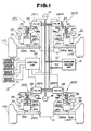
- Fig. 4 is a circuit diagram of a hydraulic circuit including the pressure source unit 16 and the working fluid chamber 26d of the hydraulic cylinder 26.
- the pressure source unit includes the pressure unit 16 which comprises a fluid pump, and is connected to the reservoir 16a via a suction pipe 201 which is driven by means of an automotive engine 200.
- the outlet of the pressure unit 16, through which the pressurized working fluid is fed, is connected to the inlet port 42i of the pressure control valve 18 via the supply line 52.
- a pressure regulating orifice 202 is disposed in the supply line 52 for suppressing pulsatile flow of the working fluid and whereby regulate the output pressure of the pressure unit 16 to be delivered to the pressure control valve 28.
- a feedback line 53 is connected to the upstream of the pressure regulating orifice 202 at one end. The other end of the feedback line 53 is connected to the upstream of the inlet of the pressure unit 16. Therefore, excessive fluid between the pressure unit 16 and the orifice 202 is fed back to the inlet side of the pressure unit.
- a pressure accumulator 203 is also connected to the supply line 52 to receive therefrom the pressurized fluid for accumulating the pressure.
- An one-way check valve 204 is disposed in the supply line 52 at the position upstream of the junction between the pressure accumulator 203 and the supply line 52.
- a pressure relief line 205 is also connected to the supply line 52 at the position intermediate between the pressure regulating orifice 202 and the one-way check valve 204, at one end. The other end of the pressure relief line 205 is connected to the drain line 54.
- a pressure relief valve 206 is disposed in the pressure relief line 205. The pressure relief valve 206 is responsive to the fluid pressure in the supply line 52 higher than a give value to drain part of the working fluid to the drain line for maintaining the pressure in the supply line 52 below the given pressure value.
- a shut-off valve 207 is disposed in the drain line 54.
- the shut-off valve 207 is also connected to the supply line 52 at upstream of the one-way check valve 204 to receive therefrom the pressure in the supply line as a pilot pressure, via pilot line 208.
- the shut-off valve 207 is designed to be maintained at open position as long as the pilot pressure to be introduced through the pilot line 208 is held at a pressure level higher than or equal to a given pressure level.
- the shut-off valve maintains fluid communication between the inlet side and outlet side thereof so that the working fluid in the drain line 54 may flow therethrough to the reservoir tank 16a.
- the shut-off valve 207 is responsive to the pilot pressure drops below the given pressure level to be switched into shut-off position. At the shut-off position, the shut-off valve blocks fluid communication between the drain port 42o and the reservoir tank 16a.
- a pressure relief valve 209 is provided in parallel relationship to the shut-off valve.
- the pressure relief valve 209 is disposed in a by-pass line 210 connecting the upstream side and downstream side of the shut-off valve 207.
- the pressure relief valve 209 is normally held at closed position to block fluid communication therethrough.
- the pressure relief valve 209 is responsive to a fluid pressure in the drain line 54 upstream thereof, higher than a set pressure, e.g. 30 kgf/cm2, in order to establish fluid communication between the upstream side and downstream side of the shut-off valve to allow the excessive pressure at the upstream side drain line 54 to be drained therethrough. Therefore, the pressure relief valve 209 limits the maximum pressure at the set pressure.
- the set pressure of the pressure relief valve 209 corresponds to a predetermined offset pressure.
- An oil cooler 211 is disposed in the drain line 54 for cooling the working fluid returning to the reservoir tank 16a.
- the fluid pump as the pressure unit 16 is driven. Therefore, the working fluid in the reservoir tank 16a is sucked via the suction pipe 201 and pressurized through the pressure unit 16.
- the pressurized working fluid is discharged from the outlet of the pressure unit 16 and fed to the pressure control valve 28 via the supply line 54 including the pressure regulating orifice 202 and the one-way check valve 204.
- the pressure control valve 28 in a position of Fig. 2, the pressurized working fluid passes the pressure control valve and introduced into the working chamber 26d of the hydraulic cylinder 26.
- the pressure control valve 28 is shifted to block communication between the supply line 52 and the working chamber 26d, the line pressure in the supply line increases.
- the line pressure in the supply line 52 becomes higher than a set pressure of the pressure relief valve 206 in the pressure relief line 205, the excessive pressure higher than the set pressure is fed to the drain line 54 via the pressure relief valve 206 and thus returned to the reservoir tank 16a.
- the fluid pressure in the supply line 52 is also fed to the shut-off valve 207 via the pilot line 208.
- the shut-off valve 207 is placed at open position as long as the pilot pressure introduced through the pilot line 208 is held higher than or equal to the set pressure thereof. Therefore, fluid communication between the pressure control valve 28 and the reservoir tank 16a is maintained. At this position, the working fluid is thus returned to the reservoir tank 16a via the drain line 54 via the shut-off valve 207 and the oil cooler 211.
- shut-off valve 207 Since the shut-off valve 207, even at the open position, serves as a resistance to the fluid flow. Therefore, the fluid pressure in the drain line 54 upstream of the shut-off valve 207 becomes excessively higher, i.e. higher than the off-set pressure P0. Then, the pressure relief valve 209 becomes active to open for allowing the excessive pressure of the working fluid to flow through the by-pass line 210.
- the pressure unit 16 cease operation.
- the working fluid pressure in the supply line 52 drops.
- the pilot pressure to be exerted to the shut-off valve 207 via the pilot line 208 drops.
- the pilot line 208 drops below or equal to the set pressure
- the shut-off valve 207 is switched into shut-off position to block fluid communication therethrough.
- the fluid pressure in the drain line 54 upstream of the shut-off valve 207 becomes equal to the pressure in the working chamber 26d. Therefore, even when the working fluid leaks through a gap between the spool valve 48 and the inner periphery of the valve bore, it will not affect the fluid pressure in the working chamber 26d.
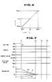
- the working fluid pressure in the working chamber 26d of the hydraulic cylinder 26 varies according to variation of the current value of the control signal applied to the pressure control valve unit 28.
- hydraulic pressure in the working chamber 26d varies between a maximum pressure P max which is saturation pressure of the pressure source unit 16 and a minimum pressure P min which is set at a magnitude in view of a noise component to be contained in the control signal.
- the maximum hydraulic pressure P max corresponds to the maximum current value I max of the control signal
- the minimum hydraulic pressure P min corresponds to the minimum current value I min of the control signal.
- the hydraulic pressure level as labeled P n represents neutral pressure at the neutral current I n .
- the neutral current value I n is set at an intermediate value between the maximum current value I max and the minimum current value I min .
- the control unit 22 comprises the microprocessor including an input/output interface, an arithmetic circuit and a memory.
- the vehivle height sensor 21 is connected to the control unit 22 to input the vehicle height indicative signals as vehicular attitude change indicative parameter.
- the control unit 22 is also connected to a pressure sensor 59 which monitors the working fluid pressure in the pressure control line 38 and produces a fluid pressure indicative signal.
- the control unit 22 is also connected to a vehicular battery 60 via a power holding circuit 62 and also via an ignition switch 64 which serves as a main switch for the electric equipments of the automotive vehicle and various components of control systems including the control unit 22.
- the power holding circuit 62 comprises a relay circuit 66 including a relay coil 68 and a movable contact 70, and an OFF-delay timer circuit 72.
- the OFF-delay timer 72 is further connected to the ignition switch 64 to receive therefrom a switch signal IS indicative of the ignitision switch position.
- the switch signal IS is also input to the control unit 22 as ignition switch position indicative data.
- the control unit 22 is connected to the positive terminal of the vehicular battery 60 via the ignition switch 64.
- the positive terminal of the vehicular battery 60 is further connected to the control unit via a relay switch 74 including the movable contact 70 which is normally open contact.
- the relay coil 68 of the relay circuit 66 is held in deenergized condition. Therefore, the normally open movable contact is held open to maintain the relay switch 74 in non-conductive state.
- the OFF-delay timer 72 is held conductive to establish connection between the relay coil 68 .
- the relay coil 68 is thus energized to shift the movable contact 70 to close the relay switch.
- the OFF-delay timer 72 is maintained conductive for a predetermined period of time after turning the switching signal IS level from HIGH level to LOW level due to turning OFF of the ignition switch.
- the OFF-delay timer 72 is herefore maintained in conductive state to maintain the circuit for connecting the positive terminal of the vehicular battery to the relay coil 68 closed.
- the relay coil 68 is held energized to cause shifting of the normally open movable contact 70 to the closed position.
- the movable contact 70 closes the relay switch 74 to establish connection between the positive terminal of the vehicular battery to the control unit 22 . Therefore, power supply for the control unit 22 is maintained for the period set in the OFF-delay time set in the OFF-delay timer.
- Fig. 6 is a flowchart of a suspension control program executed by the control unit 22 .
- the control operation to be performed by the preferred embodiment of the suspendion control system, according to the invention, will be discussed according to the processed illustrated in Fig. 6 with reference to the timing chart in Fig. 7 .
- the ignition switch position is checked at a step S102 .
- the ignition switch position is checked by checking the signal level of the switch signal IS .
- the switch signal level IS is maintained HIGH level and thus the ON position of the ignition switch 64 is detected, normal height control is performed at a step S104.
- step S104 normal mode suspension control, such as bouncing suppressive control, anti-rolling, anti-pitching control and so forth, is perfromed on the basis of various control parameters.
- control for vehicular height reguation is performed based on the vehicle height indicative signal value H D .
- the vehicle height indicative signal value H D is compared with a predetermined reference value D N which representative of a standard or neutral height position of the vehicular body.
- a suspension control value V of a control signal is derived on the basis of a difference between the vehicle height indicative signal value H D and the reference value D N for adjusting the vehicular height level at the neutral height level.
- the control signal indicative of the control value V is supplied to the plunger 58 of the pressure control valve 28 for adjusting the fluid pressure in the working chamber 26d. For instance, when the vehicle height indicative signal value H D is greater than the reference value D N , the control signal for reducing the pressure in the working chamber 26d is output. On the other hand, when the vehicle height indicative signal value H D is smaller than the reference value D N , the control signal ordering increasing of the fluid pressure in the working chamber 26d is output.
- the OFF-delay timer 70 is maintained conductive for the given period as set forth above. Therefore, power supply for the control unit is maintained for the OFF-delay period of the OFF-delay timer.
- switch signal IS turns into LOW level.
- the LOW level switch signal IS is detected at the step S102 .
- the operation mode of the control system is switched into power OFF transition mode operation.
- the power OFF transition mode operation is performed in the OFF-delay period of the OFF-delay timer 70 .
- the fluid pressure indicative signal P D from the fluid pressure sensor 59 is read out and compared with the neutral pressure P N at a step S106 .
- a pressure adjusting value v1 is derived at a step S108 .
- the pressure adjusting value v1 is variable depending upon the difference of the fluid pressure indicative signal value P D and the neutral pressure indicative value P N and indicative of magnitude of the fluid pressure to be decreased in each execution cycle so that the pressure in the working chamber 26d can be adjusted to the neutral pressure within the OFF-delay period.
- the control signal value V is modified by subtracting the pressure adjusting value v1 to derive the reduced value of the pressure control signal value.
- the control signal with the control signal value modified in the step S108 is then output to the plunger 58 of the pressure control valve 28 at the step S108 .
- a pressure adjusting value v2 is derived at a step S110 .
- the pressure adjusting value v2 is variable depending upon the difference of the fluid pressure indicative signal value P D and the neutral pressure indicative value P N and indicative of magnitude of the fluid pressure to be increased in each execution cycle so that the pressure in the working chamber 26d can be adjusted to the neutral pressure within the OFF-delay period.
- the control signal value V is modified by adding the pressure adjusting value v2 to derive the reduced value of the pressure control signal value.
- the control signal with the control signal value modified in the step S110 is then output to the plunger 58 of the pressure control valve 28 .
- the OFF-delay timer 70 is maintained in conductive state for the OFF-delay period which ends to a time t4 .
- the fluid pressure P D held higher than the neutral pressure P N is gradually lowered to the neutral pressure through the power OFF transition mode control operation.
- the fluid pressure reaches the neutral pressure P N at a time t2 as shown by line l2. It should be noted that when the fluid pressure P D is lower than the neutral pressure, the fluid pressure is gradually increased toward the neutral pressure through the process in the steps S106 and S112 , as shown by line l3 .
- the pressure in the supply line 52 of the hydraulic circuit becomes the neutral pressure.
- the pressure in the pressure accumulator 203 is drained through the pilot line 42a , the pilot chamber P of the pressure control valve 28 and the fluid path 42t is gradually reduced toward the neutral pressure.
- Speed of decreasing of the fluid pressure in the pressure accumulator 203 is lower than that in the working chamber 26d because of flow resistance in the pressure control valve.
- the shut-off valve is held open.
- the pressure in the pressure accumulator 203 reaches the neutral pressure which is equal to the pilot pressure. Then, the shut-off valve 207 is turned into the shut-off position to block fluid communication.
- the OFF-delay timer 70 becomes non-conductive to shut-off power supply for the relay coil 68 .
- the relay coil 68 is thus deenergized to open the relay switch 74 .
- power supply for the control unit 22 is terminated. Therefore, the poppet valve 56 becomes free to move.
- no vehicle height change may occur in response to termination of the control by the control unit 22 .
- the invention is also applicable for the suspension control system which employs a flow control valve for controlling amount of working fluid to flow.
- the shown embodiment employs a pressure sensor for monitoring the fluid pressure in the pressure control line and whereby monitors the pressure in the working chamber, it may possible to utilize the control signal value as a pressure indicative data because the pressure in the working chamber is controlled to the pressure represented by the control signal.
Claims (5)
- Système de commande ou de contrôle pour contrôler les caractéristiques de suspension dans un système de suspension automobile, comprenant :
un cylindre (26) disposé entre une carosserie de véhicule et un élément de suspension (24) qui supporte de façon rotative une roue (11) du véhicule, ledit cylindre définissant une chambre de travail à pression variable (26d) remplie d'un milieu de pression pour produire une force d'amortissement résistant à un déplacement relatif entre ladite carosserie de véhicule et ledit élément de suspension (24);
un moyen formant circuit de source de pression relié à ladite chambre de travail (26d) via une ligne de contrôle (38) pour amener le milieu de pression et comprenant une unité de source de pression (16) amenant le milieu de pression sous pression à travers ledit moyen formant circuit de source de pression;
une soupape de commande de pression (28) reliée à ladite unité de source de pression via une ligne d'amenée (52) et une ligne de drain (54) et à ladite chambre de travail (26d) via ladite ligne de contrôle (38), la position de la soupape pouvant varier entre un premier mode pour augmenter la pression dudit milieu de pression à l'intérieur de ladite chambre de travail (26d), un deuxième mode pour diminuer la pression dans ledit milieu de pression à l'intérieur de ladite chambre de travail (26d) et un troisième mode pour maintenir constante ladite pression dans ledit milieu de pression à l'intérieur de ladite chambre de travail;
un moyen formant capteur (21) pour surveiller un changement dans l'attitude de la carosserie de véhicule pour produire un signal de capteur indiquant un changement dans l'attitude de la carosserie de véhicule;
des moyens contrôleurs (22) pour faire dériver un signal de contrôle sur la base dudit signal indiquant un changement dans l'attitude de la carosserie de véhicule pour faire fonctionnner ladite soupape de commande de pression (28) selon l'un desdits premier, deuxième et troisième modes pour régler la pression dudit milieu de pression dans ladite chambre de travail (26d) afin de supprimer le changement d'attitude de la carosserie de véhicule;
un circuit d'amenée de puissance électrique reliant lesdits moyens contrôleurs (22) à une source de puissance électrique (60), ledit circuit d'amenée de puissance électrique comprenant un interrupteur principal de puissance (64) pour commander l'amenée de puissance audit moyen contrôleur (22); et
des moyens qui répondent à la commutation dudit interrupteur principal de puissance (64) d'une position d'amenée de puissance à une position d'arrêt de puissance pour maintenir l'amenée de puissance pour ledit moyen contrôleur (22) pendant une période de temps donnée;
caractérisé en ce que le système de contrôle ou de commande comprend un moyen de soupape de retenue (204) prévu dans ladite ligne d'amenée (52) et disposé pour permettre l'écoulement du milieu de pression de ladite unité de source de pression (16) à ladite soupape de commande de pression (28), et un moyen de soupape d'arrêt (207) prévu dans ladite ligne de drain (54) et répondant à un signal de pression pilote indiquant la pression dans ladite ligne d'amenée (52), par quoi la soupape d'arrêt est seulement maintenue dans la position ouverte aussi longtemps que la pression pilote est égale ou supérieure à une pression préréglée (Pn), et en ce que lesdits moyens contrôleurs (22) ont deux modes de fonctionnement : un mode normal pour faire dériver ledit signal de contrôle sur la base d'une valeur dudit signal indiquant un changement dans l'attitude de la carosserie de véhicule afin de supprimer le changement d'attitude du véhicule et un mode de transition d'ARRET de puissance, dans lequel la pression dans ladite chambre de travail (26d) est ajustée à ladite pression préréglée (Pn). - Système de contrôle ou de commande selon la revendication 1, caractérisé en ce que ledit interrupteur principal de puissance est constitué par un contacteur d'allumage (64).
- Système de contrôle ou de commande selon la revendication 1, caractérisé en ce que lesdits moyens contrôleurs (22) peuvent varier entre un mode de fonctionnement normal pour faire dériver ledit signal de contrôle sur la base d'une valeur dudit signal indiquant un changement dans l'attitude de la carosserie de véhicule pour supprimer le changement d'attitude du véhicule et un mode de transition d'ARRET de puissance dans lequel la pression dudit milieu de pression est réglée à une pression préréglée.
- Système de contrôle ou de commande selon la revendication 3, caractérisé en ce que lesdits moyens contrôleurs (22) font dériver ledit signal de contrôle dans ledit mode de transition d'ARRET de puissance pour régler progressivement la pression dudit milieu de pression dans ladite chambre de travail (26d) à la pression préréglée.
- Système de contrôle ou de commande selon la revendication 4, caractérisé en ce que lesdits moyens contrôleurs (22) font dériver ledit signal de contrôle dans ledit mode de transition d'ARRET de puissance afin de régler la pression dudit milieu de pression dans ladite chambre de travail (26d) pas à pas à ladite pression préréglée.
Applications Claiming Priority (2)
| Application Number | Priority Date | Filing Date | Title |
|---|---|---|---|
| JP62280071A JP2509257B2 (ja) | 1987-11-05 | 1987-11-05 | 能動型サスペンション装置 |
| JP280071/87 | 1987-11-05 |
Publications (2)
| Publication Number | Publication Date |
|---|---|
| EP0318721A1 EP0318721A1 (fr) | 1989-06-07 |
| EP0318721B1 true EP0318721B1 (fr) | 1993-03-10 |
Family
ID=17619894
Family Applications (1)
| Application Number | Title | Priority Date | Filing Date |
|---|---|---|---|
| EP88118441A Expired - Lifetime EP0318721B1 (fr) | 1987-11-05 | 1988-11-04 | Système de suspension à réglage actif avec un contrôle de l'alimentation en puissance |
Country Status (4)
| Country | Link |
|---|---|
| US (1) | US4967360A (fr) |
| EP (1) | EP0318721B1 (fr) |
| JP (1) | JP2509257B2 (fr) |
| DE (1) | DE3879121T2 (fr) |
Families Citing this family (34)
| Publication number | Priority date | Publication date | Assignee | Title |
|---|---|---|---|---|
| US5201388A (en) * | 1988-07-28 | 1993-04-13 | Ohlins Racing Ab | Shock absorber |
| JPH02225119A (ja) * | 1988-11-10 | 1990-09-07 | Toyota Motor Corp | 流体圧式サスペンション |
| JP2616038B2 (ja) * | 1989-08-31 | 1997-06-04 | 日産自動車株式会社 | 能動型サスペンション |
| DE68921590T2 (de) * | 1988-12-28 | 1995-07-27 | Aisin Seiki | Aktives hydraulisches Steuersystem, welches das Steuern der Lage eines hochbelasteten Fahrzeugs ermöglicht. |
| US5130926A (en) * | 1989-02-08 | 1992-07-14 | Aisin Seiki Kabushiki Kaisha | Pressure control system for suspension |
| JPH0814297B2 (ja) * | 1989-03-27 | 1996-02-14 | 日産自動車株式会社 | 能動型サスペンション |
| JP2528964B2 (ja) * | 1989-03-27 | 1996-08-28 | 日産自動車株式会社 | 能動型サスペンション |
| JP2506436B2 (ja) * | 1989-03-30 | 1996-06-12 | 日産自動車株式会社 | 車両用流体圧供給装置 |
| DE69023793T2 (de) * | 1989-04-04 | 1996-06-13 | Aisin Seiki | Druckregelventil. |
| JP2502367B2 (ja) * | 1989-04-20 | 1996-05-29 | 日産自動車株式会社 | 車高制御装置 |
| JP2502369B2 (ja) * | 1989-04-20 | 1996-05-29 | 日産自動車株式会社 | ソレノイド駆動装置及びこれを使用した能動型サスペンション制御装置 |
| JP3026441B2 (ja) * | 1989-04-27 | 2000-03-27 | 日産自動車株式会社 | 能動型サスペンション |
| JP2503271B2 (ja) * | 1989-04-27 | 1996-06-05 | 日産自動車株式会社 | 能動型サスペンション |
| JP2502372B2 (ja) * | 1989-04-28 | 1996-05-29 | 日産自動車株式会社 | 車両用流体圧供給装置 |
| JP2509328B2 (ja) * | 1989-04-28 | 1996-06-19 | 日産自動車株式会社 | 車両用流体圧供給装置 |
| JP2584318B2 (ja) * | 1989-07-14 | 1997-02-26 | マツダ株式会社 | 車両のサスペンション装置 |
| JP2611447B2 (ja) * | 1989-08-31 | 1997-05-21 | 日産自動車株式会社 | 能動型サスペンション |
| JP2623853B2 (ja) * | 1989-08-31 | 1997-06-25 | 日産自動車株式会社 | 能動型サスペンション |
| JP2649091B2 (ja) * | 1989-09-05 | 1997-09-03 | 株式会社 豊田中央研究所 | 高圧液体供給装置 |
| JPH0671849B2 (ja) * | 1989-09-29 | 1994-09-14 | マツダ株式会社 | 車両のサスペンション装置 |
| JP2509358B2 (ja) * | 1990-02-23 | 1996-06-19 | 日産自動車株式会社 | 能動型サスペンション |
| US5097419A (en) * | 1990-06-08 | 1992-03-17 | Monroe Auto Equipment Company | Method and apparatus for dynamic leveling |
| US5396423A (en) * | 1991-01-22 | 1995-03-07 | Nissan Motor Co., Ltd. | Automotive active suspension system for regulating vehicular height level during anti-rolling control |
| JP2757579B2 (ja) * | 1991-04-10 | 1998-05-25 | 日産自動車株式会社 | 能動型サスペンション |
| DE4221088C2 (de) * | 1992-06-26 | 2000-05-25 | Bosch Gmbh Robert | Aufhängungssystem für Fahrzeuge |
| US5682980A (en) * | 1996-02-06 | 1997-11-04 | Monroe Auto Equipment Company | Active suspension system |
| DE19812234C2 (de) * | 1998-03-20 | 2002-07-18 | Daimler Chrysler Ag | Luftfederungsanlage für Fahrzeuge |
| DE19821305A1 (de) * | 1998-05-13 | 1999-11-18 | Wabco Gmbh | Niveauregeleinrichtung |
| DE102005059116A1 (de) * | 2005-12-10 | 2007-08-16 | Zf Friedrichshafen Ag | Aktives Fahrwerk für ein Kraftfahrzeug |
| DE102007050187B4 (de) * | 2007-10-04 | 2015-06-25 | Daimler Ag | Gasfedersystem mit Mehrkammer-Gasfedern |
| DE102009022763A1 (de) * | 2009-05-27 | 2010-12-02 | Trw Automotive Gmbh | Aktives Fahrwerkstabilisierungssystem |
| US9256576B2 (en) * | 2012-11-08 | 2016-02-09 | Ford Global Technologies, Llc | Assisted direct start and active suspension integration control |
| JP6108531B2 (ja) * | 2013-03-14 | 2017-04-05 | Kyb株式会社 | 車高昇降装置 |
| US10358010B2 (en) | 2017-06-05 | 2019-07-23 | Tenneco Automotive Operating Company Inc. | Interlinked active suspension |
Citations (2)
| Publication number | Priority date | Publication date | Assignee | Title |
|---|---|---|---|---|
| US4349077A (en) * | 1978-10-02 | 1982-09-14 | Atsugi Motor Parts Co., Ltd. | Electric control device for vehicle suspension system |
| GB2159107A (en) * | 1984-05-22 | 1985-11-27 | Mitsubishi Motors Corp | Vehicle suspension apparatus |
Family Cites Families (22)
| Publication number | Priority date | Publication date | Assignee | Title |
|---|---|---|---|---|
| DE1630758A1 (de) * | 1967-12-21 | 1971-08-12 | Langen & Co | Niveauregulierte,hydropneumatische Abfederungsvorrichtung fuer Fahrzeuge |
| US3734478A (en) * | 1970-05-08 | 1973-05-22 | Hoesch Ag | Hydropneumatic shock absorbing arrangement for automotive vehicles or the like |
| BE768292A (fr) * | 1970-06-13 | 1971-12-09 | Hoesch Ag | Installation de suspension hydropneumatique avec reglage du niveau |
| FR2176599B1 (fr) * | 1972-03-24 | 1975-10-24 | Peugeot & Renault | |
| JPS593284A (ja) * | 1982-06-29 | 1984-01-09 | Tohoku Metal Ind Ltd | 盗難防止用センサ |
| JPS59121216U (ja) * | 1983-02-04 | 1984-08-15 | 三菱自動車工業株式会社 | 車高調整装置 |
| JPS59213510A (ja) * | 1983-05-20 | 1984-12-03 | Toyota Central Res & Dev Lab Inc | アクテイブ・サスペンシヨン装置 |
| US4770438A (en) * | 1984-01-20 | 1988-09-13 | Nissan Motor Co., Ltd. | Automotive suspension control system with road-condition-dependent damping characteristics |
| JPS60191809A (ja) * | 1984-03-14 | 1985-09-30 | Fuji Heavy Ind Ltd | 自動車の車高調整装置 |
| US4540188A (en) * | 1984-04-19 | 1985-09-10 | General Motors Corporation | Automatic vehicle level control |
| DE3577241D1 (de) * | 1984-12-07 | 1990-05-23 | Hitachi Ltd | Fahrzeug-hoehen-regelvorrichtung. |
| DE3524863A1 (de) * | 1985-04-12 | 1986-10-30 | Robert Bosch Gmbh, 7000 Stuttgart | Verfahren und vorrichtung zum steuern der federhaerte, insbesondere bei fahrzeugen |
| JP2532059B2 (ja) * | 1985-09-13 | 1996-09-11 | 日産自動車株式会社 | 車両のサスペンシヨン制御装置 |
| JP2589067B2 (ja) * | 1985-10-01 | 1997-03-12 | トヨタ自動車株式会社 | サスペンシヨン制御装置 |
| JPH0613246B2 (ja) * | 1985-10-01 | 1994-02-23 | トヨタ自動車株式会社 | サスペンション制御装置 |
| JPH07448B2 (ja) * | 1985-11-25 | 1995-01-11 | トヨタ自動車株式会社 | サスペンシヨン制御装置 |
| DE3768968D1 (de) * | 1986-01-30 | 1991-05-08 | Toyota Motor Co Ltd | Steuerungsverfahren fuer das fahrzeugverhalten. |
| JPH0717135B2 (ja) * | 1986-06-12 | 1995-03-01 | 日産自動車株式会社 | 車両用サスペンシヨン |
| JP2537226B2 (ja) * | 1987-03-06 | 1996-09-25 | 日産自動車株式会社 | 能動型サスペンシヨン装置 |
| JPH0829648B2 (ja) * | 1987-03-16 | 1996-03-27 | 日産自動車株式会社 | 車両用サスペンシヨン制御装置 |
| JPH0829649B2 (ja) * | 1987-03-31 | 1996-03-27 | 日産自動車株式会社 | 能動型サスペンシヨン装置 |
| JP2503227B2 (ja) * | 1987-04-06 | 1996-06-05 | 日産自動車株式会社 | 車両用油圧供給装置 |
-
1987
- 1987-11-05 JP JP62280071A patent/JP2509257B2/ja not_active Expired - Fee Related
-
1988
- 1988-11-03 US US07/266,763 patent/US4967360A/en not_active Expired - Lifetime
- 1988-11-04 EP EP88118441A patent/EP0318721B1/fr not_active Expired - Lifetime
- 1988-11-04 DE DE88118441T patent/DE3879121T2/de not_active Expired - Fee Related
Patent Citations (2)
| Publication number | Priority date | Publication date | Assignee | Title |
|---|---|---|---|---|
| US4349077A (en) * | 1978-10-02 | 1982-09-14 | Atsugi Motor Parts Co., Ltd. | Electric control device for vehicle suspension system |
| GB2159107A (en) * | 1984-05-22 | 1985-11-27 | Mitsubishi Motors Corp | Vehicle suspension apparatus |
Also Published As
| Publication number | Publication date |
|---|---|
| DE3879121T2 (de) | 1993-09-30 |
| JP2509257B2 (ja) | 1996-06-19 |
| DE3879121D1 (de) | 1993-04-15 |
| EP0318721A1 (fr) | 1989-06-07 |
| US4967360A (en) | 1990-10-30 |
| JPH01122717A (ja) | 1989-05-16 |
Similar Documents
| Publication | Publication Date | Title |
|---|---|---|
| EP0318721B1 (fr) | Système de suspension à réglage actif avec un contrôle de l'alimentation en puissance | |
| US4911470A (en) | Hydraulic circuit for actively controlled automotive suspension system | |
| US4911468A (en) | Hydraulic circuit for actively controlled suspension system with vehicle speed dependent variable fluid pressure source unit | |
| US4905152A (en) | Actively controlled suspension system with control characteristics variable depending upon vehicular speed | |
| US4919440A (en) | Actively controlled suspension system for automotive vehicle with fail-safe system in response to failure of electric circuitry | |
| US5089966A (en) | Actively controlled automotive suspension system with improved damping characteristics | |
| US5087072A (en) | Attitude change suppressive control system for active suspension system for automotive vehicle | |
| US5044660A (en) | Suspension control system for automotive vehicle with adjustment of wheel slippage dependent wheel load distribution | |
| US4948164A (en) | Actively controlled suspension system with compensation of delay in phase in control system | |
| US5013061A (en) | Hydraulic circuit for actively controlled automotive suspension system with fail-safe system | |
| EP0286072B1 (fr) | Système fournissant une pression hydraulique variable avec les conditions de fonctionnement d'un véhicule automobile | |
| EP0345816B1 (fr) | Réglage anti-dévers pour système de suspension à réglage actif de véhicule automobile ayant une sensibilité de détection du dévers augmentée | |
| EP0345817B1 (fr) | Système de réglage anti-dévers pour système de suspension active d'automobile avec caractéristiques de contrôle variables selon la friction de la route | |
| EP0395108B1 (fr) | Circuit d'alimentation de fluide pour suspension active avec source de fluide à débit variable selon la grandeur de l'accélération latérale | |
| US4961595A (en) | Active suspension system for an automotive vehicle with slip angle dependent control for enhanced steering characteristics | |
| US4911469A (en) | Actively controlled suspension system with improved layout of pressure control valve | |
| US5085459A (en) | Pressure supply network for active suspension system and control therefor | |
| US5076606A (en) | Active suspension system with hydraulic circuit having line pressure dependent flow restriction for working fluid introduced into and drained from working chamber | |
| US5042832A (en) | Proportioning valve assembly and actively controlled suspension system utilizing the same | |
| US4938499A (en) | Actively controlled automotive suspension system with engine driving condition dependent vehicular attitude control | |
| US5062660A (en) | Pressure medium fluid circuit for active suspension system with variable fluid source discharge rate depending upon magnitude of stroke in relative displacement between vehicular body and suspension member | |
| US5085460A (en) | Working fluid circuit for automotive active suspension system with enhanced take-up characteristics upon initiation of operation | |
| US5054808A (en) | Working fluid circuit for active suspension system with surge suppressive feature | |
| US5092625A (en) | Fail detecting system for electromagnetic actuator and fail-safe system for active suspension system incorporating electromagnetic actuator | |
| US4982979A (en) | Active suspension system with enhanced response characteristics hydraulic circuit |
Legal Events
| Date | Code | Title | Description |
|---|---|---|---|
| PUAI | Public reference made under article 153(3) epc to a published international application that has entered the european phase |
Free format text: ORIGINAL CODE: 0009012 |
|
| 17P | Request for examination filed |
Effective date: 19881104 |
|
| AK | Designated contracting states |
Kind code of ref document: A1 Designated state(s): DE GB |
|
| 17Q | First examination report despatched |
Effective date: 19910527 |
|
| GRAA | (expected) grant |
Free format text: ORIGINAL CODE: 0009210 |
|
| AK | Designated contracting states |
Kind code of ref document: B1 Designated state(s): DE GB |
|
| REF | Corresponds to: |
Ref document number: 3879121 Country of ref document: DE Date of ref document: 19930415 |
|
| PLBE | No opposition filed within time limit |
Free format text: ORIGINAL CODE: 0009261 |
|
| STAA | Information on the status of an ep patent application or granted ep patent |
Free format text: STATUS: NO OPPOSITION FILED WITHIN TIME LIMIT |
|
| 26N | No opposition filed | ||
| REG | Reference to a national code |
Ref country code: GB Ref legal event code: IF02 |
|
| PGFP | Annual fee paid to national office [announced via postgrant information from national office to epo] |
Ref country code: DE Payment date: 20041028 Year of fee payment: 17 |
|
| PGFP | Annual fee paid to national office [announced via postgrant information from national office to epo] |
Ref country code: GB Payment date: 20041104 Year of fee payment: 17 |
|
| PG25 | Lapsed in a contracting state [announced via postgrant information from national office to epo] |
Ref country code: GB Free format text: LAPSE BECAUSE OF NON-PAYMENT OF DUE FEES Effective date: 20051104 |
|
| PG25 | Lapsed in a contracting state [announced via postgrant information from national office to epo] |
Ref country code: DE Free format text: LAPSE BECAUSE OF NON-PAYMENT OF DUE FEES Effective date: 20060601 |
|
| GBPC | Gb: european patent ceased through non-payment of renewal fee |
Effective date: 20051104 |