EP0315941A2 - Jonction pour matériaux ayant une dilatation thermique différente - Google Patents
Jonction pour matériaux ayant une dilatation thermique différente Download PDFInfo
- Publication number
- EP0315941A2 EP0315941A2 EP88118551A EP88118551A EP0315941A2 EP 0315941 A2 EP0315941 A2 EP 0315941A2 EP 88118551 A EP88118551 A EP 88118551A EP 88118551 A EP88118551 A EP 88118551A EP 0315941 A2 EP0315941 A2 EP 0315941A2
- Authority
- EP
- European Patent Office
- Prior art keywords
- intermediate space
- thermal expansion
- connection
- parts
- spiral spring
- Prior art date
- Legal status (The legal status is an assumption and is not a legal conclusion. Google has not performed a legal analysis and makes no representation as to the accuracy of the status listed.)
- Withdrawn
Links
- 239000000463 material Substances 0.000 title claims abstract description 38
- HBMJWWWQQXIZIP-UHFFFAOYSA-N silicon carbide Chemical compound [Si+]#[C-] HBMJWWWQQXIZIP-UHFFFAOYSA-N 0.000 claims description 8
- 229910010271 silicon carbide Inorganic materials 0.000 claims description 8
- 239000002184 metal Substances 0.000 claims description 6
- 229910052751 metal Inorganic materials 0.000 claims description 6
- 239000000853 adhesive Substances 0.000 claims description 4
- 230000001070 adhesive effect Effects 0.000 claims description 4
- 150000001875 compounds Chemical class 0.000 claims 3
- 230000005540 biological transmission Effects 0.000 abstract description 4
- 239000000919 ceramic Substances 0.000 abstract description 3
- 238000010438 heat treatment Methods 0.000 abstract description 2
- 229910000831 Steel Inorganic materials 0.000 description 2
- 239000010959 steel Substances 0.000 description 2
- OKTJSMMVPCPJKN-UHFFFAOYSA-N Carbon Chemical compound [C] OKTJSMMVPCPJKN-UHFFFAOYSA-N 0.000 description 1
- 229910000997 High-speed steel Inorganic materials 0.000 description 1
- 229910010293 ceramic material Inorganic materials 0.000 description 1
- 230000007797 corrosion Effects 0.000 description 1
- 238000005260 corrosion Methods 0.000 description 1
- 229910003460 diamond Inorganic materials 0.000 description 1
- 239000010432 diamond Substances 0.000 description 1
- 229910002804 graphite Inorganic materials 0.000 description 1
- 239000010439 graphite Substances 0.000 description 1
- 230000005764 inhibitory process Effects 0.000 description 1
- 150000002739 metals Chemical class 0.000 description 1
- 238000000034 method Methods 0.000 description 1
- 230000036316 preload Effects 0.000 description 1
- 238000007493 shaping process Methods 0.000 description 1
- 230000008646 thermal stress Effects 0.000 description 1
Images


Classifications
-
- F—MECHANICAL ENGINEERING; LIGHTING; HEATING; WEAPONS; BLASTING
- F16—ENGINEERING ELEMENTS AND UNITS; GENERAL MEASURES FOR PRODUCING AND MAINTAINING EFFECTIVE FUNCTIONING OF MACHINES OR INSTALLATIONS; THERMAL INSULATION IN GENERAL
- F16D—COUPLINGS FOR TRANSMITTING ROTATION; CLUTCHES; BRAKES
- F16D3/00—Yielding couplings, i.e. with means permitting movement between the connected parts during the drive
- F16D3/50—Yielding couplings, i.e. with means permitting movement between the connected parts during the drive with the coupling parts connected by one or more intermediate members
- F16D3/76—Yielding couplings, i.e. with means permitting movement between the connected parts during the drive with the coupling parts connected by one or more intermediate members shaped as an elastic ring centered on the axis, surrounding a portion of one coupling part and surrounded by a sleeve of the other coupling part
-
- F—MECHANICAL ENGINEERING; LIGHTING; HEATING; WEAPONS; BLASTING
- F01—MACHINES OR ENGINES IN GENERAL; ENGINE PLANTS IN GENERAL; STEAM ENGINES
- F01D—NON-POSITIVE DISPLACEMENT MACHINES OR ENGINES, e.g. STEAM TURBINES
- F01D5/00—Blades; Blade-carrying members; Heating, heat-insulating, cooling or antivibration means on the blades or the members
- F01D5/02—Blade-carrying members, e.g. rotors
- F01D5/025—Fixing blade carrying members on shafts
-
- F—MECHANICAL ENGINEERING; LIGHTING; HEATING; WEAPONS; BLASTING
- F04—POSITIVE - DISPLACEMENT MACHINES FOR LIQUIDS; PUMPS FOR LIQUIDS OR ELASTIC FLUIDS
- F04D—NON-POSITIVE-DISPLACEMENT PUMPS
- F04D29/00—Details, component parts, or accessories
- F04D29/18—Rotors
- F04D29/20—Mounting rotors on shafts
-
- F—MECHANICAL ENGINEERING; LIGHTING; HEATING; WEAPONS; BLASTING
- F04—POSITIVE - DISPLACEMENT MACHINES FOR LIQUIDS; PUMPS FOR LIQUIDS OR ELASTIC FLUIDS
- F04D—NON-POSITIVE-DISPLACEMENT PUMPS
- F04D29/00—Details, component parts, or accessories
- F04D29/26—Rotors specially for elastic fluids
-
- F—MECHANICAL ENGINEERING; LIGHTING; HEATING; WEAPONS; BLASTING
- F16—ENGINEERING ELEMENTS AND UNITS; GENERAL MEASURES FOR PRODUCING AND MAINTAINING EFFECTIVE FUNCTIONING OF MACHINES OR INSTALLATIONS; THERMAL INSULATION IN GENERAL
- F16B—DEVICES FOR FASTENING OR SECURING CONSTRUCTIONAL ELEMENTS OR MACHINE PARTS TOGETHER, e.g. NAILS, BOLTS, CIRCLIPS, CLAMPS, CLIPS OR WEDGES; JOINTS OR JOINTING
- F16B37/00—Nuts or like thread-engaging members
- F16B37/12—Nuts or like thread-engaging members with thread-engaging surfaces formed by inserted coil-springs, discs, or the like; Independent pieces of wound wire used as nuts; Threaded inserts for holes
-
- F—MECHANICAL ENGINEERING; LIGHTING; HEATING; WEAPONS; BLASTING
- F16—ENGINEERING ELEMENTS AND UNITS; GENERAL MEASURES FOR PRODUCING AND MAINTAINING EFFECTIVE FUNCTIONING OF MACHINES OR INSTALLATIONS; THERMAL INSULATION IN GENERAL
- F16J—PISTONS; CYLINDERS; SEALINGS
- F16J15/00—Sealings
- F16J15/16—Sealings between relatively-moving surfaces
- F16J15/34—Sealings between relatively-moving surfaces with slip-ring pressed against a more or less radial face on one member
- F16J15/3496—Sealings between relatively-moving surfaces with slip-ring pressed against a more or less radial face on one member use of special materials
-
- F—MECHANICAL ENGINEERING; LIGHTING; HEATING; WEAPONS; BLASTING
- F16—ENGINEERING ELEMENTS AND UNITS; GENERAL MEASURES FOR PRODUCING AND MAINTAINING EFFECTIVE FUNCTIONING OF MACHINES OR INSTALLATIONS; THERMAL INSULATION IN GENERAL
- F16B—DEVICES FOR FASTENING OR SECURING CONSTRUCTIONAL ELEMENTS OR MACHINE PARTS TOGETHER, e.g. NAILS, BOLTS, CIRCLIPS, CLAMPS, CLIPS OR WEDGES; JOINTS OR JOINTING
- F16B2200/00—Constructional details of connections not covered for in other groups of this subclass
- F16B2200/97—Constructional details of connections not covered for in other groups of this subclass having differing thermal expansion coefficients
Definitions
- the invention relates to a connection of materials of different thermal expansion, in particular of machine parts rotating and concentrically arranged about a common axis.
- Typical materials with low thermal expansion are ceramic materials, for example silicon carbide, which can be exposed to particularly extreme requirements with regard to temperature, wear and corrosion properties and are used increasingly because of these advantages.
- ceramic components pose particular problems, particularly when combined with other materials with different material properties.
- connection by means of which the disadvantages mentioned can be avoided and the difficulties can be eliminated.
- connection should ensure a safe torque transmission and take into account the different thermal expansions of the materials to be connected while avoiding breakage of the ceramic components.
- the connection should also be easy and inexpensive to produce and edit.
- an elastic connecting element is arranged in a space between the two material parts, which creates a non-positive and positive connection between the material parts and the fits are dimensioned so that even when heated, no direct contact between the Sharing is given. Because a direct one Contact between the materials of different thermal expansion is avoided, a particularly high accuracy of fit is not necessary, ie high tolerances are permissible. The processing costs can be significantly reduced in this way, since otherwise the processing of silicon carbide is very costly only possible with diamond tools. Any ductile materials can be used as connecting elements with regard to the desired torque transmission.
- the intermediate space is formed spirally around the axis of rotation. This measure enables a particularly simplified introduction of the elastic connecting element into the space provided for this purpose.
- the material parts are provided with semicircular threads, which together form the intermediate space in which the connecting link is arranged. In this way, the surface pressures in the individual threads are advantageously kept small or even.
- a spiral spring is arranged as a connecting member in the intermediate space, which preferably consists of spirally wound flat material and which has the diameter of the circular through the two round threads remaining Fills in cross section.
- a connection between material parts is created, which acts positively and non-positively over the entire area of the spring.
- the expansion of the spring that occurs during heating does not fully affect the increase in the preload on the hub or shaft, but rather leads to an elongation of the spring with approximately constant surface pressures in the threads.
- There is also a high backward inhibition, ie the torque to release the connection is higher than the connection torque to be applied.
- the jacket of a commercially available Bowden cable is expediently used as the spiral spring. This is a particularly cost-effective measure, only the usually existing plastic cover having to be removed.
- the spiral spring is fixed in the intermediate space by using an adhesive. In this way it is prevented that the spiral spring changes its position, with sufficient free space for the thermal expansion of the adhesive being made available, so that no thermal stresses are exerted on the silicon carbide.
- the connector of the material part with the greater thermal expansion can be arranged on the inside and the connector of the material part with the lower thermal expansion can be arranged on the outside.
- the connector of the material part with the greater thermal expansion can also be arranged on the outside and the connector of the material part with the lower thermal expansion can be arranged on the inside.
- connection according to the invention is used between a pump impeller made of silicon carbide and a drive shaft made of metal.
- a pump impeller made of silicon carbide and a drive shaft made of metal.
- Figure 1 shows a connection according to the invention between a material (1) with low thermal expansion, for example a pump impeller made of silicon carbide, which has a receiving bore (2) for connecting a drive shaft made of steel (not shown).
- the impeller (1) and drive shaft rotate around the common axis of rotation (3).
- a likewise metallic threaded bushing (4) sits on the drive shaft (not shown) and can be connected to it via a thread (5).
- Both the main body of the pump impeller (1) and the threaded bush (4) are provided with threads or thread grooves (12, 13) which form the intermediate space (14) between them, in which a spiral spring (15) is located.
- the spiral spring (15) can be fixed in the intermediate space (14) by using a suitable adhesive, in order to prevent movement of the spiral spring (15) or unintentional loosening of the connection.
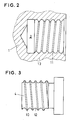
- Figure 2 shows a section of the pump impeller (1) with an inner jacket (11) and thread grooves (13), the Assembly or the connection according to the invention is carried out in such a way that the spiral spring (cf. FIG. 1, number 15) is inserted into the grooves (13) in the shaft connection opening or receiving bore (2) and then the shaft connection body (4 ) is screwed in, the semicircular thread (12) of which is adapted in shape to the spiral spring and the outer lateral surfaces (10) do not touch the inner lateral surfaces of the receiving bore of the impeller.
- the spiral spring cf. FIG. 1, number 15
- Figure 4 shows an alternative embodiment of the connection according to the invention between the connecting pin of a pump impeller (21) made of silicon carbide and the bearing bush of a drive shaft (24), in whose receiving bore (22) the connecting piece of the impeller comes to rest. Impeller (21) and drive shaft (24) rotate un the common axis of rotation (23). Between the inner casing of the bearing bush of the drive shaft (24) and the outer casing of the connecting pin of the impeller (21) there is again the gap (S), which is dimensioned such that at maximum expansion of the two connected materials (21, 24) there is no direct contact between the different materials come about. Both the base body of the pump impeller (21) and the bearing bush (24) are provided with threads or thread grooves (32, 33) which form the intermediate space (34) between them, in which the spiral spring (35) is according to the invention .
- the measures according to the invention are not limited to the exemplary embodiment shown in the drawing figures.
- any materials with different thermal expansion for example also tool steels, special high-speed steels or hard metals (Widia) can be combined with other qualities.
- the gaps for receiving the connecting links can also have any shape and can be produced in any way, for example, these can already be taken into account in the shaping or can be formed later using a variety of known methods. All known types of thread can, if appropriate, be produced with appropriately adapted connecting links.
- the respective structural design is left to the person skilled in the art to adapt to the later use of the connection.
Applications Claiming Priority (2)
| Application Number | Priority Date | Filing Date | Title |
|---|---|---|---|
| DE3738081 | 1987-11-10 | ||
| DE19873738081 DE3738081A1 (de) | 1987-11-10 | 1987-11-10 | Verbindung fuer werkstoffe unterschiedlicher waermeausdehnung |
Publications (2)
| Publication Number | Publication Date |
|---|---|
| EP0315941A2 true EP0315941A2 (fr) | 1989-05-17 |
| EP0315941A3 EP0315941A3 (fr) | 1989-11-23 |
Family
ID=6340152
Family Applications (1)
| Application Number | Title | Priority Date | Filing Date |
|---|---|---|---|
| EP88118551A Withdrawn EP0315941A3 (fr) | 1987-11-10 | 1988-11-08 | Jonction pour matériaux ayant une dilatation thermique différente |
Country Status (2)
| Country | Link |
|---|---|
| EP (1) | EP0315941A3 (fr) |
| DE (1) | DE3738081A1 (fr) |
Cited By (5)
| Publication number | Priority date | Publication date | Assignee | Title |
|---|---|---|---|---|
| EP0492603A2 (fr) * | 1990-12-27 | 1992-07-01 | Ebara Corporation | Baque d'étanchéité pour pompe |
| EP0815892A1 (fr) * | 1996-06-25 | 1998-01-07 | Schneider (Europe) Ag | Assemblage de retenue pour l'extension d'un fil de guidage |
| EP1201944A1 (fr) * | 2000-10-23 | 2002-05-02 | HILTI Aktiengesellschaft | Elément de connexion |
| CN104791016A (zh) * | 2014-01-16 | 2015-07-22 | 博世马勒涡轮系统有限两合公司 | 用于涡轮机或者压缩机或者涡轮机/压缩机几何结构的转子 |
| EP3293425A1 (fr) * | 2016-09-13 | 2018-03-14 | Siemens Aktiengesellschaft | Joint etanche aux gaz |
Families Citing this family (3)
| Publication number | Priority date | Publication date | Assignee | Title |
|---|---|---|---|---|
| DE19702796A1 (de) * | 1996-12-30 | 1998-07-02 | Widia Gmbh | Schneideinsatz |
| EP0954622B1 (fr) | 1997-01-21 | 2001-07-11 | Widia GmbH | Corps composite et procede de fabrication |
| DE10102104A1 (de) * | 2001-01-18 | 2002-07-25 | Sachtleben Chemie Gmbh | Laufradsystem für Pumpen |
Citations (3)
| Publication number | Priority date | Publication date | Assignee | Title |
|---|---|---|---|---|
| US3104583A (en) * | 1960-10-31 | 1963-09-24 | Autoclave Eng Inc | Screw connection having coil spring thread means |
| US3666302A (en) * | 1969-11-28 | 1972-05-30 | Cav Ltd | Rotor assemblies |
| DE2750870A1 (de) * | 1977-11-14 | 1979-05-17 | Krupp Gmbh | Verfahren zum anbringen von gewinden an hartmetallformkoerpern |
Family Cites Families (8)
| Publication number | Priority date | Publication date | Assignee | Title |
|---|---|---|---|---|
| GB605374A (en) * | 1941-09-02 | 1948-07-22 | Tissages A Brechard Sa Des | Device for clamping a member to a shaft |
| DE1056148B (de) * | 1956-12-21 | 1959-04-30 | Mosstype Roller Co Inc | Loesbare Verbindung zwischen Formzylinder und Welle bei Rotationsdruckmaschinen |
| DE1600208B2 (de) * | 1965-06-23 | 1971-10-21 | Williams Research Corp., Walled Lake, Mich. (V.St.A.) | Kupplung zum befestigen einer nabe aus bruchempfindlichem werkstoff auf einer welle mit unterschiedlichem waermeausdehnunnungskoeffizienten |
| SE383554B (sv) * | 1974-05-03 | 1976-03-15 | Skf Ind Trading & Dev | Lagersete samt forfarande for framstellning av detsamma |
| DE2734747A1 (de) * | 1977-08-02 | 1979-02-15 | Daimler Benz Ag | Verbindung eines keramischen turbinenrades mit einer metallischen welle |
| DE2845716C2 (de) * | 1978-10-20 | 1985-08-01 | Volkswagenwerk Ag, 3180 Wolfsburg | Thermisch hoch beanspruchbare Verbindung |
| DE3347136A1 (de) * | 1983-12-27 | 1985-07-04 | Ideal-Standard Gmbh, 5300 Bonn | Formschluessige verbindung |
| DE3545135A1 (de) * | 1984-12-19 | 1986-06-26 | Honda Giken Kogyo K.K., Tokio/Tokyo | Fittingeinheit |
-
1987
- 1987-11-10 DE DE19873738081 patent/DE3738081A1/de not_active Withdrawn
-
1988
- 1988-11-08 EP EP88118551A patent/EP0315941A3/fr not_active Withdrawn
Patent Citations (3)
| Publication number | Priority date | Publication date | Assignee | Title |
|---|---|---|---|---|
| US3104583A (en) * | 1960-10-31 | 1963-09-24 | Autoclave Eng Inc | Screw connection having coil spring thread means |
| US3666302A (en) * | 1969-11-28 | 1972-05-30 | Cav Ltd | Rotor assemblies |
| DE2750870A1 (de) * | 1977-11-14 | 1979-05-17 | Krupp Gmbh | Verfahren zum anbringen von gewinden an hartmetallformkoerpern |
Cited By (11)
| Publication number | Priority date | Publication date | Assignee | Title |
|---|---|---|---|---|
| EP0492603A2 (fr) * | 1990-12-27 | 1992-07-01 | Ebara Corporation | Baque d'étanchéité pour pompe |
| EP0492603A3 (en) * | 1990-12-27 | 1992-09-02 | Ebara Corporation | Liner ring for a pump |
| US5295786A (en) * | 1990-12-27 | 1994-03-22 | Ebara Corporation | Liner ring for a pump |
| EP0815892A1 (fr) * | 1996-06-25 | 1998-01-07 | Schneider (Europe) Ag | Assemblage de retenue pour l'extension d'un fil de guidage |
| US6039700A (en) * | 1996-06-25 | 2000-03-21 | Schneider (Europe) A.G. | Docking assembly for the extension of a guidewire |
| EP1201944A1 (fr) * | 2000-10-23 | 2002-05-02 | HILTI Aktiengesellschaft | Elément de connexion |
| CN104791016A (zh) * | 2014-01-16 | 2015-07-22 | 博世马勒涡轮系统有限两合公司 | 用于涡轮机或者压缩机或者涡轮机/压缩机几何结构的转子 |
| EP3293425A1 (fr) * | 2016-09-13 | 2018-03-14 | Siemens Aktiengesellschaft | Joint etanche aux gaz |
| WO2018050406A1 (fr) | 2016-09-13 | 2018-03-22 | Siemens Aktiengesellschaft | Garniture à gaz |
| RU2697018C1 (ru) * | 2016-09-13 | 2019-08-08 | Сименс Акциенгезелльшафт | Газовое уплотнение |
| US10648570B2 (en) | 2016-09-13 | 2020-05-12 | Siemens Aktiengesellschaft | Gas seal |
Also Published As
| Publication number | Publication date |
|---|---|
| EP0315941A3 (fr) | 1989-11-23 |
| DE3738081A1 (de) | 1989-05-18 |
Similar Documents
| Publication | Publication Date | Title |
|---|---|---|
| DE2730338C2 (de) | Bolzenführung für den Bremssattel einer Teilbelagscheibenbremse | |
| DE3619063C2 (fr) | ||
| DE2905683A1 (de) | Lagerbaugruppe | |
| DE2921352A1 (de) | Elastischer ring zur festlegung von gerillten oder gezahnten bauteilen | |
| DE2816155C2 (de) | Käfig für die Kugeln eines Gleichlaufdrehgelenkes | |
| DE3129220C2 (fr) | ||
| EP0777830A1 (fr) | Etrier pour frein a disque | |
| DE3149596A1 (de) | Verbindung von teilen | |
| EP0315941A2 (fr) | Jonction pour matériaux ayant une dilatation thermique différente | |
| DE2509140A1 (de) | Bohrwerkzeug mit bohrer und aufnahmeteil | |
| DE2439886A1 (de) | Armbanduhrgehaeuse | |
| DE19833159B4 (de) | Rohrplatine für eine Wischeranlage | |
| EP0186695A1 (fr) | Arbre creux | |
| DE4029026A1 (de) | Welle fuer verbrennungsmotoren | |
| DE3005058A1 (de) | Radialturbinenlaeufer | |
| DE3600677C2 (fr) | ||
| DE4016051C2 (de) | Mantelpenetrator | |
| EP1476262A2 (fr) | Cylindre de coulee et procede de production d'un cylindre de coulee | |
| DE3112754C2 (de) | Befestigung von Lagern | |
| DD296011A5 (de) | Walzring | |
| EP0303845B1 (fr) | Arbre creux et procédé pour sa fabrication | |
| DE4014752A1 (de) | Laengsschneidarm fuer vortriebs- und abbauzwecke u. dgl. | |
| DE10125042A1 (de) | Mit Flansch versehener Kugelstift | |
| DE1911812B2 (de) | Verfahren zum Einbau eines Hochseeschiffpropellers | |
| EP0156010A1 (fr) | Elément de construction en matériaux polymériques |
Legal Events
| Date | Code | Title | Description |
|---|---|---|---|
| PUAI | Public reference made under article 153(3) epc to a published international application that has entered the european phase |
Free format text: ORIGINAL CODE: 0009012 |
|
| 17P | Request for examination filed |
Effective date: 19881118 |
|
| AK | Designated contracting states |
Kind code of ref document: A2 Designated state(s): AT BE CH DE FR GB IT LI NL |
|
| PUAL | Search report despatched |
Free format text: ORIGINAL CODE: 0009013 |
|
| AK | Designated contracting states |
Kind code of ref document: A3 Designated state(s): AT BE CH DE FR GB IT LI NL |
|
| 17Q | First examination report despatched |
Effective date: 19910108 |
|
| STAA | Information on the status of an ep patent application or granted ep patent |
Free format text: STATUS: THE APPLICATION IS DEEMED TO BE WITHDRAWN |
|
| 18D | Application deemed to be withdrawn |
Effective date: 19910522 |