EP0315941A2 - Junction for materials of different thermal expansion - Google Patents
Junction for materials of different thermal expansion Download PDFInfo
- Publication number
- EP0315941A2 EP0315941A2 EP88118551A EP88118551A EP0315941A2 EP 0315941 A2 EP0315941 A2 EP 0315941A2 EP 88118551 A EP88118551 A EP 88118551A EP 88118551 A EP88118551 A EP 88118551A EP 0315941 A2 EP0315941 A2 EP 0315941A2
- Authority
- EP
- European Patent Office
- Prior art keywords
- intermediate space
- thermal expansion
- connection
- parts
- spiral spring
- Prior art date
- Legal status (The legal status is an assumption and is not a legal conclusion. Google has not performed a legal analysis and makes no representation as to the accuracy of the status listed.)
- Withdrawn
Links
- 239000000463 material Substances 0.000 title claims abstract description 38
- HBMJWWWQQXIZIP-UHFFFAOYSA-N silicon carbide Chemical compound [Si+]#[C-] HBMJWWWQQXIZIP-UHFFFAOYSA-N 0.000 claims description 8
- 229910010271 silicon carbide Inorganic materials 0.000 claims description 8
- 239000002184 metal Substances 0.000 claims description 6
- 229910052751 metal Inorganic materials 0.000 claims description 6
- 239000000853 adhesive Substances 0.000 claims description 4
- 230000001070 adhesive effect Effects 0.000 claims description 4
- 150000001875 compounds Chemical class 0.000 claims 3
- 230000005540 biological transmission Effects 0.000 abstract description 4
- 239000000919 ceramic Substances 0.000 abstract description 3
- 238000010438 heat treatment Methods 0.000 abstract description 2
- 229910000831 Steel Inorganic materials 0.000 description 2
- 239000010959 steel Substances 0.000 description 2
- OKTJSMMVPCPJKN-UHFFFAOYSA-N Carbon Chemical compound [C] OKTJSMMVPCPJKN-UHFFFAOYSA-N 0.000 description 1
- 229910000997 High-speed steel Inorganic materials 0.000 description 1
- 229910010293 ceramic material Inorganic materials 0.000 description 1
- 230000007797 corrosion Effects 0.000 description 1
- 238000005260 corrosion Methods 0.000 description 1
- 229910003460 diamond Inorganic materials 0.000 description 1
- 239000010432 diamond Substances 0.000 description 1
- 229910002804 graphite Inorganic materials 0.000 description 1
- 239000010439 graphite Substances 0.000 description 1
- 230000005764 inhibitory process Effects 0.000 description 1
- 150000002739 metals Chemical class 0.000 description 1
- 238000000034 method Methods 0.000 description 1
- 230000036316 preload Effects 0.000 description 1
- 238000007493 shaping process Methods 0.000 description 1
- 230000008646 thermal stress Effects 0.000 description 1
Images


Classifications
-
- F—MECHANICAL ENGINEERING; LIGHTING; HEATING; WEAPONS; BLASTING
- F16—ENGINEERING ELEMENTS AND UNITS; GENERAL MEASURES FOR PRODUCING AND MAINTAINING EFFECTIVE FUNCTIONING OF MACHINES OR INSTALLATIONS; THERMAL INSULATION IN GENERAL
- F16D—COUPLINGS FOR TRANSMITTING ROTATION; CLUTCHES; BRAKES
- F16D3/00—Yielding couplings, i.e. with means permitting movement between the connected parts during the drive
- F16D3/50—Yielding couplings, i.e. with means permitting movement between the connected parts during the drive with the coupling parts connected by one or more intermediate members
- F16D3/76—Yielding couplings, i.e. with means permitting movement between the connected parts during the drive with the coupling parts connected by one or more intermediate members shaped as an elastic ring centered on the axis, surrounding a portion of one coupling part and surrounded by a sleeve of the other coupling part
-
- F—MECHANICAL ENGINEERING; LIGHTING; HEATING; WEAPONS; BLASTING
- F01—MACHINES OR ENGINES IN GENERAL; ENGINE PLANTS IN GENERAL; STEAM ENGINES
- F01D—NON-POSITIVE DISPLACEMENT MACHINES OR ENGINES, e.g. STEAM TURBINES
- F01D5/00—Blades; Blade-carrying members; Heating, heat-insulating, cooling or antivibration means on the blades or the members
- F01D5/02—Blade-carrying members, e.g. rotors
- F01D5/025—Fixing blade carrying members on shafts
-
- F—MECHANICAL ENGINEERING; LIGHTING; HEATING; WEAPONS; BLASTING
- F04—POSITIVE - DISPLACEMENT MACHINES FOR LIQUIDS; PUMPS FOR LIQUIDS OR ELASTIC FLUIDS
- F04D—NON-POSITIVE-DISPLACEMENT PUMPS
- F04D29/00—Details, component parts, or accessories
- F04D29/18—Rotors
- F04D29/20—Mounting rotors on shafts
-
- F—MECHANICAL ENGINEERING; LIGHTING; HEATING; WEAPONS; BLASTING
- F04—POSITIVE - DISPLACEMENT MACHINES FOR LIQUIDS; PUMPS FOR LIQUIDS OR ELASTIC FLUIDS
- F04D—NON-POSITIVE-DISPLACEMENT PUMPS
- F04D29/00—Details, component parts, or accessories
- F04D29/26—Rotors specially for elastic fluids
-
- F—MECHANICAL ENGINEERING; LIGHTING; HEATING; WEAPONS; BLASTING
- F16—ENGINEERING ELEMENTS AND UNITS; GENERAL MEASURES FOR PRODUCING AND MAINTAINING EFFECTIVE FUNCTIONING OF MACHINES OR INSTALLATIONS; THERMAL INSULATION IN GENERAL
- F16B—DEVICES FOR FASTENING OR SECURING CONSTRUCTIONAL ELEMENTS OR MACHINE PARTS TOGETHER, e.g. NAILS, BOLTS, CIRCLIPS, CLAMPS, CLIPS OR WEDGES; JOINTS OR JOINTING
- F16B37/00—Nuts or like thread-engaging members
- F16B37/12—Nuts or like thread-engaging members with thread-engaging surfaces formed by inserted coil-springs, discs, or the like; Independent pieces of wound wire used as nuts; Threaded inserts for holes
-
- F—MECHANICAL ENGINEERING; LIGHTING; HEATING; WEAPONS; BLASTING
- F16—ENGINEERING ELEMENTS AND UNITS; GENERAL MEASURES FOR PRODUCING AND MAINTAINING EFFECTIVE FUNCTIONING OF MACHINES OR INSTALLATIONS; THERMAL INSULATION IN GENERAL
- F16J—PISTONS; CYLINDERS; SEALINGS
- F16J15/00—Sealings
- F16J15/16—Sealings between relatively-moving surfaces
- F16J15/34—Sealings between relatively-moving surfaces with slip-ring pressed against a more or less radial face on one member
- F16J15/3496—Sealings between relatively-moving surfaces with slip-ring pressed against a more or less radial face on one member use of special materials
-
- F—MECHANICAL ENGINEERING; LIGHTING; HEATING; WEAPONS; BLASTING
- F16—ENGINEERING ELEMENTS AND UNITS; GENERAL MEASURES FOR PRODUCING AND MAINTAINING EFFECTIVE FUNCTIONING OF MACHINES OR INSTALLATIONS; THERMAL INSULATION IN GENERAL
- F16B—DEVICES FOR FASTENING OR SECURING CONSTRUCTIONAL ELEMENTS OR MACHINE PARTS TOGETHER, e.g. NAILS, BOLTS, CIRCLIPS, CLAMPS, CLIPS OR WEDGES; JOINTS OR JOINTING
- F16B2200/00—Constructional details of connections not covered for in other groups of this subclass
- F16B2200/97—Constructional details of connections not covered for in other groups of this subclass having differing thermal expansion coefficients
Abstract
Description
Die Erfindung bezieht sich auf eine Verbindung von Werkstoffen unterschiedlicher Wärmeausdehnung, insbesondere von sich um eine gemeinsame Achse drehenden und konzentrisch angeordneten Maschinenteilen.The invention relates to a connection of materials of different thermal expansion, in particular of machine parts rotating and concentrically arranged about a common axis.
Typische Werkstoffe mit geringer Wärmeausdehnung sind keramische Materialien, beispielsweise Silicumcarbid, das besonders extremen Anforderungen hinsichtlich der Temperatur-, Verschleiß- und Korrosionseigenschaften ausgesetzt werden kann und wegen dieser Vorteile zunehmend Verwendung findet. Die Erfahrung hat gezeigt, daß keramische Bauteile besondere Probleme insbesondere bei einer Verbindung mit anderen Werkstoffen mit anderen Werkstoffeigenschaften bereiten. Obwohl in vielen technischen Bereichen bereits befriedigende Lösungen gefunden wurden, bleiben für spezielle Anwendungsfälle, insbesondere bei der konstruktiven Verbindung von sich drehenden Maschinenteilen die bekannten Lösungen unbefriedigend.Typical materials with low thermal expansion are ceramic materials, for example silicon carbide, which can be exposed to particularly extreme requirements with regard to temperature, wear and corrosion properties and are used increasingly because of these advantages. Experience has shown that ceramic components pose particular problems, particularly when combined with other materials with different material properties. Although satisfactory solutions have already been found in many technical areas, the known solutions remain unsatisfactory for special applications, in particular in the structural connection of rotating machine parts.
Aus der DE-OS 3428744 ist für Gleitringdichtungen oder Wellenschutzhülsen eine Befestigung von ringförmigen Siliciumcarbid-Bauteilen an Metallträgerteilen bekannt, wobei zwischen dem Metallträgerteil mindestens ein elastisches Lagerglied angeordnet ist, das vorzugsweise aus hochtemperaturbeständigem Graphit oder aus wellenförmigen Metallringen besteht. Auf diese Weise wird nur eine kraftschlüssige Verbindung hergestellt, eine formschlüssige Verbindung zur sicheren Übertragung hoher Drehmomente ist nicht vorgesehen.DE-OS 3428744 for mechanical seals or shaft protection sleeves an attachment of annular silicon carbide components to metal carrier parts is known, wherein at least one elastic bearing member is arranged between the metal carrier part, which preferably consists of high temperature-resistant graphite or wavy metal rings. In this way, only a non-positive connection is established; a positive connection for the safe transmission of high torques is not provided.
Es ist daher Aufgabe der Erfindung, eine Verbindung vorzustellen, mittels derer die genannten Nachteile vermieden und die Schwierigkeiten ausgeräumt werden können. Insbesondere soll die Verbindung eine sichere Momentenübertragung gewährleisten und die unterschiedlichen Wärmeausdehnungen der zu verbindenden Werkstoffe berücksichtigen unter Vermeidung eines Bruchs der Keramikbauteile. Die Verbindung soll gleichzeitig auch leicht und kostengünsitig herstellbar und bearbeitbar sein.It is therefore an object of the invention to provide a connection by means of which the disadvantages mentioned can be avoided and the difficulties can be eliminated. In particular, the connection should ensure a safe torque transmission and take into account the different thermal expansions of the materials to be connected while avoiding breakage of the ceramic components. The connection should also be easy and inexpensive to produce and edit.
Die Lösung der gestellten Aufgabe gelingt erfindungsgemäß dadurch, daß in einem Zwischenraum zwischen beiden Werkstoffteilen ein elastisches Verbindungsglied angeordnet ist, das eine kraft- und formschlüssige Verbindung zwischen der Werkstoffteilen herstellt und wobei die Passungen so dimensioniert sind, daß auch bei Erwärmung keine direkte Berührung zwischen den Teilen gegeben ist. Da eine direkte Berührung zwischen den Werkstoffen unterschiedlicher Wärmedehnung vermieden wird, ist auch eine besonders hohe Paßgenauigkeit nicht erforderlich, d.h. es sind hohe Toleranzen zulässig. Die Bearbeitungskosten können auf diese Weise erheblich gesenkt werden, da ansonsten die Bearbeitung von Siliciumcarbid sehr kostenintensiv nur mit Diamantwerkzeugen möglich ist. Als Verbindungsglieder können beliebige duktile Werkstoffe im Hinblick auf die gewünschte Momentenübertragung verwendet werden.The solution to the problem is achieved according to the invention in that an elastic connecting element is arranged in a space between the two material parts, which creates a non-positive and positive connection between the material parts and the fits are dimensioned so that even when heated, no direct contact between the Sharing is given. Because a direct one Contact between the materials of different thermal expansion is avoided, a particularly high accuracy of fit is not necessary, ie high tolerances are permissible. The processing costs can be significantly reduced in this way, since otherwise the processing of silicon carbide is very costly only possible with diamond tools. Any ductile materials can be used as connecting elements with regard to the desired torque transmission.
Als vorteilhafte Ausgestaltung der Erfindung ist der Zwischenraum spiralförmig um die Drehachse ausgebildet. Mit dieser Maßnahme wird ein besonders vereinfachtes Einbringen des elastischen Verbindungselementes in den dafür vorgesehenen Zwischenraum ermöglicht.As an advantageous embodiment of the invention, the intermediate space is formed spirally around the axis of rotation. This measure enables a particularly simplified introduction of the elastic connecting element into the space provided for this purpose.
In einer weiteren Ausgestaltung der Erfindung sind die Werkstoffteile mit Halbrundgewinden versehen, die gemeinsam den Zwischenraum bilden, in dem das Verbindungslied angeordnet ist. Auf diese Weise werden vorteilhaft die Flächenpressungen in den einzelnen Gewindegängen kleingehalten bzw. vergleichmäßigt.In a further embodiment of the invention, the material parts are provided with semicircular threads, which together form the intermediate space in which the connecting link is arranged. In this way, the surface pressures in the individual threads are advantageously kept small or even.
Besonders vorteilhaft ist nach der Erfindung vorgesehen, daß als Verbindungsglied im Zwischenraum eine Spiralfeder angeordnet ist, die vorzugsweise aus spiralförmig gewickeltem Flachmaterial besteht und welche mit ihrem Durchmesser den durch die beiden Rundgewindegänge verbleibenden kreisförmigen Querschnitt ausfüllt. Auf diese Weise wird eine Verbindung zwischen Werkstoffteilen geschaffen, die über den gesamte Bereich der Feder form- und kraftschlüssig wirkt. Die bei Erwärmung entstehende Dehnung der Feder wirkt sich nicht in vollem Umfang in einer Erhöhung der Vorspannung auf die Nabe bzw. Welle aus, sondern führt zu einer Längung der Feder bei in etwa gleichbleibenden Flächenpressungen in den Gewindegängen. Es tritt ferner eine hohe Rückwärtshemmung ein, d. h. das Drehmoment zu Lösen der Verbindung ist höher als das aufzubringende Verbindungsmoment.It is particularly advantageously provided according to the invention that a spiral spring is arranged as a connecting member in the intermediate space, which preferably consists of spirally wound flat material and which has the diameter of the circular through the two round threads remaining Fills in cross section. In this way, a connection between material parts is created, which acts positively and non-positively over the entire area of the spring. The expansion of the spring that occurs during heating does not fully affect the increase in the preload on the hub or shaft, but rather leads to an elongation of the spring with approximately constant surface pressures in the threads. There is also a high backward inhibition, ie the torque to release the connection is higher than the connection torque to be applied.
Zweckmäßigerweise wird als Spiralfeder der Mantel eines handelsüblichen Bowdenzuges verwendet. Hierbei handelt es sich um eine besonders kostengünstige Maßnahme, wobei lediglich die üblicherweise vorhandene Kunststoffhülle entfernt werden muß.The jacket of a commercially available Bowden cable is expediently used as the spiral spring. This is a particularly cost-effective measure, only the usually existing plastic cover having to be removed.
Ferner ist nach der Erfindung mit Vorteil vorgesehen, daß die Spiralfeder durch Verwendung eines Klebers im Zwischenraum fixiert ist. Auf diese Weise wird verhindert, daß die Spiralfeder ihre Lage verändert, wobei genügend Freiraum zur thermischen Ausdehnung des Klebers zur Verfügung gestellt wird, so daß keine thermischen Spannungen auf das Siliciumcarbid ausgeübt werden.Furthermore, it is advantageously provided according to the invention that the spiral spring is fixed in the intermediate space by using an adhesive. In this way it is prevented that the spiral spring changes its position, with sufficient free space for the thermal expansion of the adhesive being made available, so that no thermal stresses are exerted on the silicon carbide.
Bei der Erfindung kann das Verbindungsstück des Werkstoffteils mit der größeren Wärmedehnung innen und das Verbindungsstück des Werkstoffteils mit der geringeren Wärmedehnung außen angeordnet sein.In the invention, the connector of the material part with the greater thermal expansion can be arranged on the inside and the connector of the material part with the lower thermal expansion can be arranged on the outside.
Alternativ kann das Verbindungsstück des Werkstoffteils mit der größeren Wärmedehnung aber auch außen und das Verbindungsstück des Werkstoffteils mit der geringeren Wärmedehnung innen angeordnet sein.Alternatively, the connector of the material part with the greater thermal expansion can also be arranged on the outside and the connector of the material part with the lower thermal expansion can be arranged on the inside.
Nach einer besonders bevorzugten Ausführungsform wird die erfindungsgemäße Verbindung zwischen einem Pumpenlaufrad aus Siliciumcarbid und einer Antriebswelle aus Metall eingesetzt. Bei diesem speziellen, aber nur beispielhaften Anwendungsfall wurde eine besonders hohe Betriebssicherheit und Laufruhe festgestellt.According to a particularly preferred embodiment, the connection according to the invention is used between a pump impeller made of silicon carbide and a drive shaft made of metal. In this special, but only exemplary application, a particularly high level of operational reliability and smooth running was found.
Weitere Einzelheiten, Merkmale und Vorteile der Erfindung ergeben sich aus der nachstehenden Erläuterung mehrerer in den Zeichnungen schematisch dargestellter Ausführungsbeispiele.Further details, features and advantages of the invention result from the following explanation of several exemplary embodiments shown schematically in the drawings.
Es zeigen:
- Fig. 1 eine erfindungsgemäße Gewindebefestigung eines Pumpenlaufrades mit einer Antriebswelle, ausschnittweise, schematisch in geschnittener Seitenansicht,
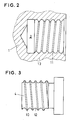
- Fig. 2 Aufnahmebohrung eines Pumpenlaufrades im Teilschnitt mit Gewinderillen zur Aufnahme einer Spiralfeder,
- Fig. 3 Antriebswelle bzw. Gewindebuchse in Seitenansicht mit Gewinderillen,
- Fig. 4 eine erfindungsgemäße Verbindung zwischen Antriebswelle und innenliegendem Zapfen eines Pumpenlaufrades in vergrößertem, schematischen Teilschnitt.
- 1 shows a threaded fastening according to the invention of a pump impeller with a drive shaft, in sections, schematically in a sectional side view,
- 2 receiving bore of a pump impeller in partial section with thread grooves for receiving a coil spring,
- 3 drive shaft or threaded bushing in side view with thread grooves,
- Fig. 4 shows a connection according to the invention between the drive shaft and the inner pin of a pump impeller in an enlarged, schematic partial section.
Figure 1 zeigt eine erfindungsgemäße Verbindung zwischen einem Werkstoff (1) mit einer geringen Wärmedehnung, beispielsweise einem Pumpenlaufrad aus Siliciumcarbid, das eine Aufnahmebohrung (2) zum Anschluß einer Antriebswelle aus Stahl (nicht dargestellt) besitzt. Laufrad (1) und Antriebswelle rotieren um die gemeinsame Drehachse (3). Auf der nicht gezeigten Antriebswelle sitzt eine ebenfalls metallische Gewindebuchse (4), die mit dieser über ein Gewinde (5) verbindbar ist. Zwischen dem Außenmantel (10) der Gewindebuchse (4) und dem Innenmantel (11) des Laufrades (1) besteht ein Spalt (S), der so bemessen ist, daß bei maximaler Ausdehnung der beiden verbundenen Werkstoffe (1, 4) keine direkte Berührung der unterschiedlichen Materialien zustande kommt. Sowohl der Grundkörper des Pumpenlaufrades (1) als auch die Gewindebuchse (4) sind mit Gewinde bzw. Gewinderillen (12, 13) versehen, die zwischen sich den Zwischenraum (14) bilden, in dem sich eine Spiralfeder (15) befindet. Die Spiralfeder (15) kann durch Verwendung eines geeigneten Klebers im Zwischenraum (14) fixiert sein, um auf diese Weise eine Bewegung der Spiralfeder (15) bzw. ein unbeabsichtigtes Lösen der Verbindung zu verhindern.Figure 1 shows a connection according to the invention between a material (1) with low thermal expansion, for example a pump impeller made of silicon carbide, which has a receiving bore (2) for connecting a drive shaft made of steel (not shown). The impeller (1) and drive shaft rotate around the common axis of rotation (3). A likewise metallic threaded bushing (4) sits on the drive shaft (not shown) and can be connected to it via a thread (5). There is a gap (S) between the outer casing (10) of the threaded bushing (4) and the inner casing (11) of the impeller (1), which is dimensioned such that there is no direct contact when the two connected materials (1, 4) are maximally expanded the different materials come about. Both the main body of the pump impeller (1) and the threaded bush (4) are provided with threads or thread grooves (12, 13) which form the intermediate space (14) between them, in which a spiral spring (15) is located. The spiral spring (15) can be fixed in the intermediate space (14) by using a suitable adhesive, in order to prevent movement of the spiral spring (15) or unintentional loosening of the connection.
Figure 2 zeigt ausschnittweise das Pumpenlaufrad (1) mit Innenmantel (11) und Gewinderillen (13), wobei die Montage bzw. die erfindungsgemäße Verbindung in der Weise erfolgt, daß in die Wellenanschlußöffnung bzw. Aufnahmebohrung (2) in die Rillen (13) die Spiralfeder (vgl. Fig. 1, Ziffer 15) eingelegt und anschließend der in Figure 3 gezeigte Wellenanschlußkörper (4) eingedreht wird, dessen Halbrundgewinde (12) formmäßig an die Spiralfeder angepaßt sind und wobei die Außenmantelflächen (10) die Innenmantelflächen der Aufnahmebohrung des Laufrades nicht berühren.Figure 2 shows a section of the pump impeller (1) with an inner jacket (11) and thread grooves (13), the Assembly or the connection according to the invention is carried out in such a way that the spiral spring (cf. FIG. 1, number 15) is inserted into the grooves (13) in the shaft connection opening or receiving bore (2) and then the shaft connection body (4 ) is screwed in, the semicircular thread (12) of which is adapted in shape to the spiral spring and the outer lateral surfaces (10) do not touch the inner lateral surfaces of the receiving bore of the impeller.
Figure 4 zeigt eine alternative Ausgestaltung der erfindungsgemäßen Verbindung zwischen dem Verbindungszapfen eines Pumpenlaufrades (21) aus Siliciumcarbid und der Lagerbuchse einer Antriebswelle (24), in deren Aufnahmebohrung (22) das Verbindungsstück des Laufrades zu liegen kommt. Laufrad (21) und Antriebswelle (24) rotieren un die gemeinsame Drehachse (23). Zwischen dem Innenmantel der Lagerbuchse der Antriebswelle (24) und dem Außenmantel des Verbindungszapfens des Laufrades (21) besteht wiederum der Spalt (S), der so bemessen ist, daß bei maximaler Ausdehnung der beiden verbundenen Werkstoffe (21, 24) keine direkte Berührung der unterschiedlichen Materialien zustande kommt. Sowohl der Grundkörper des Pumpenlaufrades (21) als auch die Lagerbuchse (24) sind mit Gewinde bzw. Gewinderillen (32, 33) versehen, die zwischen sich den Zwischenraum (34) bilden, in dem sich nach der Erfindung die Spiralfeder (35) befindet.Figure 4 shows an alternative embodiment of the connection according to the invention between the connecting pin of a pump impeller (21) made of silicon carbide and the bearing bush of a drive shaft (24), in whose receiving bore (22) the connecting piece of the impeller comes to rest. Impeller (21) and drive shaft (24) rotate un the common axis of rotation (23). Between the inner casing of the bearing bush of the drive shaft (24) and the outer casing of the connecting pin of the impeller (21) there is again the gap (S), which is dimensioned such that at maximum expansion of the two connected materials (21, 24) there is no direct contact between the different materials come about. Both the base body of the pump impeller (21) and the bearing bush (24) are provided with threads or thread grooves (32, 33) which form the intermediate space (34) between them, in which the spiral spring (35) is according to the invention .
Die erfindungsgemäßen Maßnahmen sind nicht auf das in den Zeichnungsfiguren dargestellte Ausführungsbeispiel beschränkt. So können beispielsweise, ohne den Rahmen der Erfindung zu verlassen, beliebige Werkstoffe mit unterschiedlicher Wärmeausdehnung, beispielsweise auch Werkzeug-, besondere Schnellarbeitsstähle oder Hartmetalle (Widia) mit anderen Qualitäten verbunden werden. Die Zwischenräume zur Aufnahme der Verbindungsglieder können ferner eine beliebige Form haben und in beliebiger Weise hergestellt werden, beispielsweise können diese bereits bei der Formgebung Berücksichtigung finden oder später mittels verschiedenster bekannter Verfahren gebildet werden. Es können alle bekannten Gewindearten nach Zweckmäßigkeitsgesichtspunkten gegebenenfalls mit formmäßig angepaßten Verbindungsgliedern hergestellt werden. Die jeweilige konstruktive Ausgestaltung ist in Anpassung an die spätere Verwendung der Verbindung dem Fachmann anheimgestellt.The measures according to the invention are not limited to the exemplary embodiment shown in the drawing figures. For example, without the frame to leave the invention, any materials with different thermal expansion, for example also tool steels, special high-speed steels or hard metals (Widia) can be combined with other qualities. The gaps for receiving the connecting links can also have any shape and can be produced in any way, for example, these can already be taken into account in the shaping or can be formed later using a variety of known methods. All known types of thread can, if appropriate, be produced with appropriately adapted connecting links. The respective structural design is left to the person skilled in the art to adapt to the later use of the connection.
Claims (9)
dadurch gekennzeichnet, daß die Werkstoffteile (1, 4; 21, 24) mit Halbrundgewinden (12, 13; 32, 33) versehen sind, die gemeinsam den Zwischenraum (14; 34) bilden, in dem das Verbindungsglied (15; 35) angeordnet ist.3. A compound according to claim 1 or 2,
characterized in that the material parts (1, 4; 21, 24) are provided with semicircular threads (12, 13; 32, 33) which together form the intermediate space (14; 34) in which the connecting member (15; 35) is arranged is.
dadurch gekennzeichnet, daß die Spiralfeder (15; 35) durch Verwendung eines Klebers im Zwischenraum (14; 34) fixiert ist.6. Connection according to one or more of the preceding claims 1 to 5,
characterized in that the spiral spring (15; 35) is fixed in the intermediate space (14; 34) by using an adhesive.
dadurch gekennzeichnet, daß das Verbindungsstück des Werkstoffteils mit der größeren Wärmedehnung (4) innen und das Verbindungsstück des Werkstoffteils mit der geringeren Wärmedehnung (1) außen angeordnet ist,7. Connection according to one or more of the preceding claims 1 to 6,
characterized in that the connecting piece of the material part with the greater thermal expansion (4) is arranged on the inside and the connecting piece of the material part with the lower thermal expansion (1) is arranged on the outside,
dadurch gekennzeichnet, daß das Verbindungsstück des Werkstoffteils mit der größeren Wärmedehnung (24) außen und das Verbindungsstück des Werkstoffteils mit der geringeren Wärmedehnung (21) innen angeordnet ist,8. A compound according to one or more of the preceding claims 1 to 6,
characterized in that the connecting piece of the material part with the greater thermal expansion (24) is arranged on the outside and the connecting piece of the material part with the lower thermal expansion (21) is arranged on the inside,
dadurch gekennzeichnet, daß sie zwischen einem Pumpenlaufrad (1; 21) aus Siliciumcarbid und einer Antriebswelle (4; 24) aus Metall gebildet wird.9. A compound according to one or more of the preceding claims 1 to 8,
characterized in that it is formed between a pump impeller (1; 21) made of silicon carbide and a drive shaft (4; 24) made of metal.
Applications Claiming Priority (2)
| Application Number | Priority Date | Filing Date | Title |
|---|---|---|---|
| DE19873738081 DE3738081A1 (en) | 1987-11-10 | 1987-11-10 | CONNECTION FOR MATERIALS OF DIFFERENT HEAT EXPANSION |
| DE3738081 | 1987-11-10 |
Publications (2)
| Publication Number | Publication Date |
|---|---|
| EP0315941A2 true EP0315941A2 (en) | 1989-05-17 |
| EP0315941A3 EP0315941A3 (en) | 1989-11-23 |
Family
ID=6340152
Family Applications (1)
| Application Number | Title | Priority Date | Filing Date |
|---|---|---|---|
| EP88118551A Withdrawn EP0315941A3 (en) | 1987-11-10 | 1988-11-08 | Junction for materials of different thermal expansion |
Country Status (2)
| Country | Link |
|---|---|
| EP (1) | EP0315941A3 (en) |
| DE (1) | DE3738081A1 (en) |
Cited By (5)
| Publication number | Priority date | Publication date | Assignee | Title |
|---|---|---|---|---|
| EP0492603A2 (en) * | 1990-12-27 | 1992-07-01 | Ebara Corporation | Liner ring for a pump |
| EP0815892A1 (en) * | 1996-06-25 | 1998-01-07 | Schneider (Europe) Ag | Docking assembly for the extension of a guidewire |
| EP1201944A1 (en) * | 2000-10-23 | 2002-05-02 | HILTI Aktiengesellschaft | Connector |
| CN104791016A (en) * | 2014-01-16 | 2015-07-22 | 博世马勒涡轮系统有限两合公司 | Rotor for a turbine of a compressor or a turbine/compressor geometry |
| EP3293425A1 (en) * | 2016-09-13 | 2018-03-14 | Siemens Aktiengesellschaft | Gas seal |
Families Citing this family (3)
| Publication number | Priority date | Publication date | Assignee | Title |
|---|---|---|---|---|
| DE19702796A1 (en) * | 1996-12-30 | 1998-07-02 | Widia Gmbh | Cutting insert |
| WO1998031846A1 (en) | 1997-01-21 | 1998-07-23 | Widia Gmbh | Composite body and production process |
| DE10102104A1 (en) * | 2001-01-18 | 2002-07-25 | Sachtleben Chemie Gmbh | Impeller system for pumps |
Citations (3)
| Publication number | Priority date | Publication date | Assignee | Title |
|---|---|---|---|---|
| US3104583A (en) * | 1960-10-31 | 1963-09-24 | Autoclave Eng Inc | Screw connection having coil spring thread means |
| US3666302A (en) * | 1969-11-28 | 1972-05-30 | Cav Ltd | Rotor assemblies |
| DE2750870A1 (en) * | 1977-11-14 | 1979-05-17 | Krupp Gmbh | Screw thread for carbide component - consists of attached steel wire on carbide machined to correct size |
Family Cites Families (8)
| Publication number | Priority date | Publication date | Assignee | Title |
|---|---|---|---|---|
| GB605374A (en) * | 1941-09-02 | 1948-07-22 | Tissages A Brechard Sa Des | Device for clamping a member to a shaft |
| DE1056148B (en) * | 1956-12-21 | 1959-04-30 | Mosstype Roller Co Inc | Detachable connection between forme cylinder and shaft in rotary printing machines |
| DE1600208B2 (en) * | 1965-06-23 | 1971-10-21 | Williams Research Corp., Walled Lake, Mich. (V.St.A.) | COUPLING FOR FASTENING A HUB MADE OF SENSITIVE MATERIAL ON A SHAFT WITH DIFFERENT THERMAL EXPANSION COEFFICIENTS |
| SE383554B (en) * | 1974-05-03 | 1976-03-15 | Skf Ind Trading & Dev | STORAGE SEAT AND PROCEDURE FOR PRODUCING THE SAME |
| DE2734747A1 (en) * | 1977-08-02 | 1979-02-15 | Daimler Benz Ag | Mounting for ceramic turbine rotor on metal shaft - uses shrink or friction fit or friction welding at end faces |
| DE2845716C2 (en) * | 1978-10-20 | 1985-08-01 | Volkswagenwerk Ag, 3180 Wolfsburg | Thermally highly stressable connection |
| DE3347136A1 (en) * | 1983-12-27 | 1985-07-04 | Ideal-Standard Gmbh, 5300 Bonn | POSITIVE-LOCKING CONNECTION |
| GB2169058B (en) * | 1984-12-19 | 1989-01-05 | Honda Motor Co Ltd | Fitting assembly |
-
1987
- 1987-11-10 DE DE19873738081 patent/DE3738081A1/en not_active Withdrawn
-
1988
- 1988-11-08 EP EP88118551A patent/EP0315941A3/en not_active Withdrawn
Patent Citations (3)
| Publication number | Priority date | Publication date | Assignee | Title |
|---|---|---|---|---|
| US3104583A (en) * | 1960-10-31 | 1963-09-24 | Autoclave Eng Inc | Screw connection having coil spring thread means |
| US3666302A (en) * | 1969-11-28 | 1972-05-30 | Cav Ltd | Rotor assemblies |
| DE2750870A1 (en) * | 1977-11-14 | 1979-05-17 | Krupp Gmbh | Screw thread for carbide component - consists of attached steel wire on carbide machined to correct size |
Cited By (11)
| Publication number | Priority date | Publication date | Assignee | Title |
|---|---|---|---|---|
| EP0492603A2 (en) * | 1990-12-27 | 1992-07-01 | Ebara Corporation | Liner ring for a pump |
| EP0492603A3 (en) * | 1990-12-27 | 1992-09-02 | Ebara Corporation | Liner ring for a pump |
| US5295786A (en) * | 1990-12-27 | 1994-03-22 | Ebara Corporation | Liner ring for a pump |
| EP0815892A1 (en) * | 1996-06-25 | 1998-01-07 | Schneider (Europe) Ag | Docking assembly for the extension of a guidewire |
| US6039700A (en) * | 1996-06-25 | 2000-03-21 | Schneider (Europe) A.G. | Docking assembly for the extension of a guidewire |
| EP1201944A1 (en) * | 2000-10-23 | 2002-05-02 | HILTI Aktiengesellschaft | Connector |
| CN104791016A (en) * | 2014-01-16 | 2015-07-22 | 博世马勒涡轮系统有限两合公司 | Rotor for a turbine of a compressor or a turbine/compressor geometry |
| EP3293425A1 (en) * | 2016-09-13 | 2018-03-14 | Siemens Aktiengesellschaft | Gas seal |
| WO2018050406A1 (en) | 2016-09-13 | 2018-03-22 | Siemens Aktiengesellschaft | Gas seal |
| RU2697018C1 (en) * | 2016-09-13 | 2019-08-08 | Сименс Акциенгезелльшафт | Gas seal |
| US10648570B2 (en) | 2016-09-13 | 2020-05-12 | Siemens Aktiengesellschaft | Gas seal |
Also Published As
| Publication number | Publication date |
|---|---|
| DE3738081A1 (en) | 1989-05-18 |
| EP0315941A3 (en) | 1989-11-23 |
Similar Documents
| Publication | Publication Date | Title |
|---|---|---|
| DE2730338C2 (en) | Bolt guide for the brake calliper of a partially lined disc brake | |
| DE3619063C2 (en) | ||
| DE2905683A1 (en) | BEARING ASSEMBLY | |
| DE2921352A1 (en) | ELASTIC RING FOR FASTENING GROOVED OR TOOTHED COMPONENTS | |
| DE2816155C2 (en) | Cage for the balls of a constant velocity swivel | |
| EP0777830A1 (en) | Disk brake calliper | |
| DE3149596A1 (en) | CONNECTING PARTS | |
| EP0315941A2 (en) | Junction for materials of different thermal expansion | |
| DE2509140A1 (en) | DRILLING TOOL WITH DRILL AND ADAPTER | |
| DE2439886A1 (en) | WATCH CASE | |
| DE19833159B4 (en) | Tube board for a wiper system | |
| EP0186695A1 (en) | Hollow shaft | |
| DE4029026A1 (en) | SHAFT FOR INTERNAL COMBUSTION ENGINES | |
| DE3005058A1 (en) | Radial turbine rotor with reduced moment of inertia - achieved by using hollow rotor hub engaging shaft via teeth allowing radial movement | |
| CH677836A5 (en) | ||
| DE3600677C2 (en) | ||
| DE4016051C2 (en) | Jacket penetrator | |
| EP1476262A2 (en) | Casting roll and a method for producing a casting roll | |
| DE3112754C2 (en) | Fixing of bearings | |
| DD296011A5 (en) | ROLLING RING | |
| EP0303845B1 (en) | Hollow shaft and process for producing it | |
| DE4014752A1 (en) | LENGTH CUTTING ARM FOR DRIVING AND DISASSEMBLY AND THE LIKE | |
| DE10125042A1 (en) | Flanged ball pin | |
| DE1911812B2 (en) | Procedure for installing an ocean-going ship propeller | |
| EP0156010A1 (en) | Construction element of polymeric material |
Legal Events
| Date | Code | Title | Description |
|---|---|---|---|
| PUAI | Public reference made under article 153(3) epc to a published international application that has entered the european phase |
Free format text: ORIGINAL CODE: 0009012 |
|
| 17P | Request for examination filed |
Effective date: 19881118 |
|
| AK | Designated contracting states |
Kind code of ref document: A2 Designated state(s): AT BE CH DE FR GB IT LI NL |
|
| PUAL | Search report despatched |
Free format text: ORIGINAL CODE: 0009013 |
|
| AK | Designated contracting states |
Kind code of ref document: A3 Designated state(s): AT BE CH DE FR GB IT LI NL |
|
| 17Q | First examination report despatched |
Effective date: 19910108 |
|
| STAA | Information on the status of an ep patent application or granted ep patent |
Free format text: STATUS: THE APPLICATION IS DEEMED TO BE WITHDRAWN |
|
| 18D | Application deemed to be withdrawn |
Effective date: 19910522 |