EP0309987B1 - Steuersystem für einen unter Druck stehenden Flüssigkeitskreislauf - Google Patents
Steuersystem für einen unter Druck stehenden Flüssigkeitskreislauf Download PDFInfo
- Publication number
- EP0309987B1 EP0309987B1 EP88115881A EP88115881A EP0309987B1 EP 0309987 B1 EP0309987 B1 EP 0309987B1 EP 88115881 A EP88115881 A EP 88115881A EP 88115881 A EP88115881 A EP 88115881A EP 0309987 B1 EP0309987 B1 EP 0309987B1
- Authority
- EP
- European Patent Office
- Prior art keywords
- flow passage
- valve
- selector valve
- fluid pressure
- pressure
- Prior art date
- Legal status (The legal status is an assumption and is not a legal conclusion. Google has not performed a legal analysis and makes no representation as to the accuracy of the status listed.)
- Expired
Links
- 239000012530 fluid Substances 0.000 title claims description 214
- 230000007246 mechanism Effects 0.000 claims description 27
- 238000006073 displacement reaction Methods 0.000 claims description 20
- 230000007935 neutral effect Effects 0.000 claims description 14
- 230000001276 controlling effect Effects 0.000 description 7
- 238000010586 diagram Methods 0.000 description 6
- 230000001105 regulatory effect Effects 0.000 description 5
- 230000003247 decreasing effect Effects 0.000 description 2
- 238000001514 detection method Methods 0.000 description 1
- 239000007788 liquid Substances 0.000 description 1
- 238000012986 modification Methods 0.000 description 1
- 230000004048 modification Effects 0.000 description 1
- 230000000630 rising effect Effects 0.000 description 1
Images


Classifications
-
- F—MECHANICAL ENGINEERING; LIGHTING; HEATING; WEAPONS; BLASTING
- F15—FLUID-PRESSURE ACTUATORS; HYDRAULICS OR PNEUMATICS IN GENERAL
- F15B—SYSTEMS ACTING BY MEANS OF FLUIDS IN GENERAL; FLUID-PRESSURE ACTUATORS, e.g. SERVOMOTORS; DETAILS OF FLUID-PRESSURE SYSTEMS, NOT OTHERWISE PROVIDED FOR
- F15B11/00—Servomotor systems without provision for follow-up action; Circuits therefor
- F15B11/16—Servomotor systems without provision for follow-up action; Circuits therefor with two or more servomotors
-
- E—FIXED CONSTRUCTIONS
- E02—HYDRAULIC ENGINEERING; FOUNDATIONS; SOIL SHIFTING
- E02F—DREDGING; SOIL-SHIFTING
- E02F9/00—Component parts of dredgers or soil-shifting machines, not restricted to one of the kinds covered by groups E02F3/00 - E02F7/00
- E02F9/08—Superstructures; Supports for superstructures
- E02F9/10—Supports for movable superstructures mounted on travelling or walking gears or on other superstructures
- E02F9/12—Slewing or traversing gears
- E02F9/121—Turntables, i.e. structure rotatable about 360°
- E02F9/123—Drives or control devices specially adapted therefor
-
- E—FIXED CONSTRUCTIONS
- E02—HYDRAULIC ENGINEERING; FOUNDATIONS; SOIL SHIFTING
- E02F—DREDGING; SOIL-SHIFTING
- E02F9/00—Component parts of dredgers or soil-shifting machines, not restricted to one of the kinds covered by groups E02F3/00 - E02F7/00
- E02F9/20—Drives; Control devices
- E02F9/22—Hydraulic or pneumatic drives
- E02F9/2221—Control of flow rate; Load sensing arrangements
- E02F9/2232—Control of flow rate; Load sensing arrangements using one or more variable displacement pumps
-
- E—FIXED CONSTRUCTIONS
- E02—HYDRAULIC ENGINEERING; FOUNDATIONS; SOIL SHIFTING
- E02F—DREDGING; SOIL-SHIFTING
- E02F9/00—Component parts of dredgers or soil-shifting machines, not restricted to one of the kinds covered by groups E02F3/00 - E02F7/00
- E02F9/20—Drives; Control devices
- E02F9/22—Hydraulic or pneumatic drives
- E02F9/2278—Hydraulic circuits
- E02F9/2285—Pilot-operated systems
-
- E—FIXED CONSTRUCTIONS
- E02—HYDRAULIC ENGINEERING; FOUNDATIONS; SOIL SHIFTING
- E02F—DREDGING; SOIL-SHIFTING
- E02F9/00—Component parts of dredgers or soil-shifting machines, not restricted to one of the kinds covered by groups E02F3/00 - E02F7/00
- E02F9/20—Drives; Control devices
- E02F9/22—Hydraulic or pneumatic drives
- E02F9/2278—Hydraulic circuits
- E02F9/2292—Systems with two or more pumps
-
- E—FIXED CONSTRUCTIONS
- E02—HYDRAULIC ENGINEERING; FOUNDATIONS; SOIL SHIFTING
- E02F—DREDGING; SOIL-SHIFTING
- E02F9/00—Component parts of dredgers or soil-shifting machines, not restricted to one of the kinds covered by groups E02F3/00 - E02F7/00
- E02F9/20—Drives; Control devices
- E02F9/22—Hydraulic or pneumatic drives
- E02F9/2278—Hydraulic circuits
- E02F9/2296—Systems with a variable displacement pump
-
- F—MECHANICAL ENGINEERING; LIGHTING; HEATING; WEAPONS; BLASTING
- F15—FLUID-PRESSURE ACTUATORS; HYDRAULICS OR PNEUMATICS IN GENERAL
- F15B—SYSTEMS ACTING BY MEANS OF FLUIDS IN GENERAL; FLUID-PRESSURE ACTUATORS, e.g. SERVOMOTORS; DETAILS OF FLUID-PRESSURE SYSTEMS, NOT OTHERWISE PROVIDED FOR
- F15B2211/00—Circuits for servomotor systems
- F15B2211/20—Fluid pressure source, e.g. accumulator or variable axial piston pump
- F15B2211/205—Systems with pumps
- F15B2211/2053—Type of pump
- F15B2211/20546—Type of pump variable capacity
- F15B2211/20553—Type of pump variable capacity with pilot circuit, e.g. for controlling a swash plate
-
- F—MECHANICAL ENGINEERING; LIGHTING; HEATING; WEAPONS; BLASTING
- F15—FLUID-PRESSURE ACTUATORS; HYDRAULICS OR PNEUMATICS IN GENERAL
- F15B—SYSTEMS ACTING BY MEANS OF FLUIDS IN GENERAL; FLUID-PRESSURE ACTUATORS, e.g. SERVOMOTORS; DETAILS OF FLUID-PRESSURE SYSTEMS, NOT OTHERWISE PROVIDED FOR
- F15B2211/00—Circuits for servomotor systems
- F15B2211/20—Fluid pressure source, e.g. accumulator or variable axial piston pump
- F15B2211/25—Pressure control functions
-
- F—MECHANICAL ENGINEERING; LIGHTING; HEATING; WEAPONS; BLASTING
- F15—FLUID-PRESSURE ACTUATORS; HYDRAULICS OR PNEUMATICS IN GENERAL
- F15B—SYSTEMS ACTING BY MEANS OF FLUIDS IN GENERAL; FLUID-PRESSURE ACTUATORS, e.g. SERVOMOTORS; DETAILS OF FLUID-PRESSURE SYSTEMS, NOT OTHERWISE PROVIDED FOR
- F15B2211/00—Circuits for servomotor systems
- F15B2211/30—Directional control
- F15B2211/305—Directional control characterised by the type of valves
- F15B2211/30525—Directional control valves, e.g. 4/3-directional control valve
- F15B2211/3053—In combination with a pressure compensating valve
- F15B2211/30555—Inlet and outlet of the pressure compensating valve being connected to the directional control valve
-
- F—MECHANICAL ENGINEERING; LIGHTING; HEATING; WEAPONS; BLASTING
- F15—FLUID-PRESSURE ACTUATORS; HYDRAULICS OR PNEUMATICS IN GENERAL
- F15B—SYSTEMS ACTING BY MEANS OF FLUIDS IN GENERAL; FLUID-PRESSURE ACTUATORS, e.g. SERVOMOTORS; DETAILS OF FLUID-PRESSURE SYSTEMS, NOT OTHERWISE PROVIDED FOR
- F15B2211/00—Circuits for servomotor systems
- F15B2211/30—Directional control
- F15B2211/32—Directional control characterised by the type of actuation
- F15B2211/329—Directional control characterised by the type of actuation actuated by fluid pressure
-
- F—MECHANICAL ENGINEERING; LIGHTING; HEATING; WEAPONS; BLASTING
- F15—FLUID-PRESSURE ACTUATORS; HYDRAULICS OR PNEUMATICS IN GENERAL
- F15B—SYSTEMS ACTING BY MEANS OF FLUIDS IN GENERAL; FLUID-PRESSURE ACTUATORS, e.g. SERVOMOTORS; DETAILS OF FLUID-PRESSURE SYSTEMS, NOT OTHERWISE PROVIDED FOR
- F15B2211/00—Circuits for servomotor systems
- F15B2211/30—Directional control
- F15B2211/35—Directional control combined with flow control
- F15B2211/351—Flow control by regulating means in feed line, i.e. meter-in control
-
- F—MECHANICAL ENGINEERING; LIGHTING; HEATING; WEAPONS; BLASTING
- F15—FLUID-PRESSURE ACTUATORS; HYDRAULICS OR PNEUMATICS IN GENERAL
- F15B—SYSTEMS ACTING BY MEANS OF FLUIDS IN GENERAL; FLUID-PRESSURE ACTUATORS, e.g. SERVOMOTORS; DETAILS OF FLUID-PRESSURE SYSTEMS, NOT OTHERWISE PROVIDED FOR
- F15B2211/00—Circuits for servomotor systems
- F15B2211/30—Directional control
- F15B2211/35—Directional control combined with flow control
- F15B2211/353—Flow control by regulating means in return line, i.e. meter-out control
-
- F—MECHANICAL ENGINEERING; LIGHTING; HEATING; WEAPONS; BLASTING
- F15—FLUID-PRESSURE ACTUATORS; HYDRAULICS OR PNEUMATICS IN GENERAL
- F15B—SYSTEMS ACTING BY MEANS OF FLUIDS IN GENERAL; FLUID-PRESSURE ACTUATORS, e.g. SERVOMOTORS; DETAILS OF FLUID-PRESSURE SYSTEMS, NOT OTHERWISE PROVIDED FOR
- F15B2211/00—Circuits for servomotor systems
- F15B2211/30—Directional control
- F15B2211/355—Pilot pressure control
-
- F—MECHANICAL ENGINEERING; LIGHTING; HEATING; WEAPONS; BLASTING
- F15—FLUID-PRESSURE ACTUATORS; HYDRAULICS OR PNEUMATICS IN GENERAL
- F15B—SYSTEMS ACTING BY MEANS OF FLUIDS IN GENERAL; FLUID-PRESSURE ACTUATORS, e.g. SERVOMOTORS; DETAILS OF FLUID-PRESSURE SYSTEMS, NOT OTHERWISE PROVIDED FOR
- F15B2211/00—Circuits for servomotor systems
- F15B2211/50—Pressure control
- F15B2211/505—Pressure control characterised by the type of pressure control means
- F15B2211/50509—Pressure control characterised by the type of pressure control means the pressure control means controlling a pressure upstream of the pressure control means
- F15B2211/50518—Pressure control characterised by the type of pressure control means the pressure control means controlling a pressure upstream of the pressure control means using pressure relief valves
- F15B2211/50527—Pressure control characterised by the type of pressure control means the pressure control means controlling a pressure upstream of the pressure control means using pressure relief valves using cross-pressure relief valves
-
- F—MECHANICAL ENGINEERING; LIGHTING; HEATING; WEAPONS; BLASTING
- F15—FLUID-PRESSURE ACTUATORS; HYDRAULICS OR PNEUMATICS IN GENERAL
- F15B—SYSTEMS ACTING BY MEANS OF FLUIDS IN GENERAL; FLUID-PRESSURE ACTUATORS, e.g. SERVOMOTORS; DETAILS OF FLUID-PRESSURE SYSTEMS, NOT OTHERWISE PROVIDED FOR
- F15B2211/00—Circuits for servomotor systems
- F15B2211/50—Pressure control
- F15B2211/505—Pressure control characterised by the type of pressure control means
- F15B2211/50563—Pressure control characterised by the type of pressure control means the pressure control means controlling a differential pressure
- F15B2211/50581—Pressure control characterised by the type of pressure control means the pressure control means controlling a differential pressure using counterbalance valves
- F15B2211/5059—Pressure control characterised by the type of pressure control means the pressure control means controlling a differential pressure using counterbalance valves using double counterbalance valves
-
- F—MECHANICAL ENGINEERING; LIGHTING; HEATING; WEAPONS; BLASTING
- F15—FLUID-PRESSURE ACTUATORS; HYDRAULICS OR PNEUMATICS IN GENERAL
- F15B—SYSTEMS ACTING BY MEANS OF FLUIDS IN GENERAL; FLUID-PRESSURE ACTUATORS, e.g. SERVOMOTORS; DETAILS OF FLUID-PRESSURE SYSTEMS, NOT OTHERWISE PROVIDED FOR
- F15B2211/00—Circuits for servomotor systems
- F15B2211/50—Pressure control
- F15B2211/515—Pressure control characterised by the connections of the pressure control means in the circuit
- F15B2211/5153—Pressure control characterised by the connections of the pressure control means in the circuit being connected to an output member and a directional control valve
- F15B2211/5154—Pressure control characterised by the connections of the pressure control means in the circuit being connected to an output member and a directional control valve being connected to multiple ports of an output member
-
- F—MECHANICAL ENGINEERING; LIGHTING; HEATING; WEAPONS; BLASTING
- F15—FLUID-PRESSURE ACTUATORS; HYDRAULICS OR PNEUMATICS IN GENERAL
- F15B—SYSTEMS ACTING BY MEANS OF FLUIDS IN GENERAL; FLUID-PRESSURE ACTUATORS, e.g. SERVOMOTORS; DETAILS OF FLUID-PRESSURE SYSTEMS, NOT OTHERWISE PROVIDED FOR
- F15B2211/00—Circuits for servomotor systems
- F15B2211/60—Circuit components or control therefor
- F15B2211/605—Load sensing circuits
- F15B2211/6051—Load sensing circuits having valve means between output member and the load sensing circuit
- F15B2211/6054—Load sensing circuits having valve means between output member and the load sensing circuit using shuttle valves
-
- F—MECHANICAL ENGINEERING; LIGHTING; HEATING; WEAPONS; BLASTING
- F15—FLUID-PRESSURE ACTUATORS; HYDRAULICS OR PNEUMATICS IN GENERAL
- F15B—SYSTEMS ACTING BY MEANS OF FLUIDS IN GENERAL; FLUID-PRESSURE ACTUATORS, e.g. SERVOMOTORS; DETAILS OF FLUID-PRESSURE SYSTEMS, NOT OTHERWISE PROVIDED FOR
- F15B2211/00—Circuits for servomotor systems
- F15B2211/60—Circuit components or control therefor
- F15B2211/605—Load sensing circuits
- F15B2211/6051—Load sensing circuits having valve means between output member and the load sensing circuit
- F15B2211/6055—Load sensing circuits having valve means between output member and the load sensing circuit using pressure relief valves
-
- F—MECHANICAL ENGINEERING; LIGHTING; HEATING; WEAPONS; BLASTING
- F15—FLUID-PRESSURE ACTUATORS; HYDRAULICS OR PNEUMATICS IN GENERAL
- F15B—SYSTEMS ACTING BY MEANS OF FLUIDS IN GENERAL; FLUID-PRESSURE ACTUATORS, e.g. SERVOMOTORS; DETAILS OF FLUID-PRESSURE SYSTEMS, NOT OTHERWISE PROVIDED FOR
- F15B2211/00—Circuits for servomotor systems
- F15B2211/60—Circuit components or control therefor
- F15B2211/605—Load sensing circuits
- F15B2211/6051—Load sensing circuits having valve means between output member and the load sensing circuit
- F15B2211/6057—Load sensing circuits having valve means between output member and the load sensing circuit using directional control valves
-
- F—MECHANICAL ENGINEERING; LIGHTING; HEATING; WEAPONS; BLASTING
- F15—FLUID-PRESSURE ACTUATORS; HYDRAULICS OR PNEUMATICS IN GENERAL
- F15B—SYSTEMS ACTING BY MEANS OF FLUIDS IN GENERAL; FLUID-PRESSURE ACTUATORS, e.g. SERVOMOTORS; DETAILS OF FLUID-PRESSURE SYSTEMS, NOT OTHERWISE PROVIDED FOR
- F15B2211/00—Circuits for servomotor systems
- F15B2211/60—Circuit components or control therefor
- F15B2211/635—Circuits providing pilot pressure to pilot pressure-controlled fluid circuit elements
- F15B2211/6355—Circuits providing pilot pressure to pilot pressure-controlled fluid circuit elements having valve means
-
- F—MECHANICAL ENGINEERING; LIGHTING; HEATING; WEAPONS; BLASTING
- F15—FLUID-PRESSURE ACTUATORS; HYDRAULICS OR PNEUMATICS IN GENERAL
- F15B—SYSTEMS ACTING BY MEANS OF FLUIDS IN GENERAL; FLUID-PRESSURE ACTUATORS, e.g. SERVOMOTORS; DETAILS OF FLUID-PRESSURE SYSTEMS, NOT OTHERWISE PROVIDED FOR
- F15B2211/00—Circuits for servomotor systems
- F15B2211/60—Circuit components or control therefor
- F15B2211/65—Methods of control of the load sensing pressure
-
- F—MECHANICAL ENGINEERING; LIGHTING; HEATING; WEAPONS; BLASTING
- F15—FLUID-PRESSURE ACTUATORS; HYDRAULICS OR PNEUMATICS IN GENERAL
- F15B—SYSTEMS ACTING BY MEANS OF FLUIDS IN GENERAL; FLUID-PRESSURE ACTUATORS, e.g. SERVOMOTORS; DETAILS OF FLUID-PRESSURE SYSTEMS, NOT OTHERWISE PROVIDED FOR
- F15B2211/00—Circuits for servomotor systems
- F15B2211/70—Output members, e.g. hydraulic motors or cylinders or control therefor
- F15B2211/71—Multiple output members, e.g. multiple hydraulic motors or cylinders
- F15B2211/7135—Combinations of output members of different types, e.g. single-acting cylinders with rotary motors
Definitions
- This invention relates to a fluid pressure control system for controlling a plurality of actuators. More specifically, it relates to a fluid pressure control system suitable for, but not exclusively, controlling the actuation of a fluid pressure cylinder mechanism for vertically moving a boom and a fluid pressure motor for swinging an upper swing frame in a hydraulic excavator.
- a hydraulic excavator is provided with an upper swing frame mounted pivotally on a moving undercarriage, a boom mounted on the upper swing frame for free vertical movement and a bucket mounted pivotally on the end portion of the boom via an arm.
- the upper swing frame is caused to swing by the action of the fluid pressure motor, and the boom is actuated vertically by the extention and retraction of a fluid pressure cylinder mechanism for the boom.
- the bucket is actuated by the extention and retraction of a fluid pressure cylinder mechanism for the bucket.
- a fluid pressure control system comprising a variable displacement pump of which amount of discharge is variable, a first selector valve adapted to be selectively held at any one of a neutral position, a first operative position and a second operative position, a second selector valve adapted to be selectively held at any one of a neutral position, a first operative position and a second operative position, a first actuator of which action is to be controlled by the shifting operation of the first selector valve, a second actuator of which action is to be controlled by the shifting operation of the second selector valve, a first flow control valve for controlling a fluid to be supplied to the first actuator, a second flow control valve for controlling a fluid to be supplied to the second actuator, a feed flow passage connecting the variable displacement pump to the first and second selector valves, a return flow passage connected to the first and second selector valves, a first and a second flow passage connecting the first selector
- the illustrated hydraulic excavator is provided with a vehicle body shown at 2 having a moving undercarriage 4 which may be formed by tracks.
- An upper swing frame 6 is mounted on the upper end portion of the vehicle body 2 so as to be free to swing about a vertically extending pivot axis and adapted to swing in the manner to be described by the action of a fluid pressure motor 8 such as a hydraulic motor.
- a fluid pressure motor 8 such as a hydraulic motor.
- One end portion of a boom 10 is pivotally mounted on the upper swing frame 6, and a fluid pressure cylinder mechanism 12 for the boom, such as a hydraulic cylinder, is interposed between the boom 10 and the upper swing frame 6. Accordingly, when the fluid pressure cylinder mechanism 12 is extended (or retracted), the boom 10 moves upwardly (or downwardly).
- An arm 14 is pivotally mounted on the other end portion of the boom 10, and a fluid pressure cylinder mechanism 16 for the arm is interposed between the boom 10 and the arm 14.
- a bucket 18 as a working device is mounted pivotally on the front end portion of the arm 14.
- a fluid pressure cylinder mechanism 20 for the bucket is interposed between the arm 14 and the bucket 18. Hence, the arm 14 and the bucket 18 are actuated by the extention and retraction of the fluid pressure cylinder mechanisms 16 and 20.
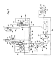
- the operations of the fluid pressure motor 8 and the fluid pressure cylinder mechanism 12 for the boom in the hydraulic excavator are controlled by the fluid pressure control system shown in Figure 2.
- the fluid pressure cylinder mechanism 16 for the arm, the fluid pressure cylinder mechanism 20 for the bucket and fluid pressure motors in the moving undercarridge are also controlled by the fluid pressure control system shown in Figure 2. But for easy understanding, these members are omitted in Figure 2.
- the illustrated fluid pressure control system is equipped with a first selector valve 22 for controlling the operation of the fluid pressure cylinder mechanism 12 (constituting a first actuator) for the boom and a second selector valve 24 for controlling the operation of the fluid pressure motor 8 (constituting a second actuator).
- the first selector valve 22 and the retracting side (rod side) of the fluid pressure cylinder mechanism 12 are connected via a first flow passage 26, and the first selector valve 22 and the extending side (head side) of the fluid pressure cylinder mechanism 12 are connected via a second flow passage 28.
- the second selector valve 24 is connected to one connecting portion of the fluid pressure motor 8 via a third flow passage 30, and to the other connecting portion of the fluid pressure motor 8 via a fourth flow passage 21.
- the illustrated system further comprises a fluid reservoir such as an oil tank and a supply source for supplying a fluid in the fluid reservoir 34.
- the supply source is constructed of a variable displacement pump 36 of which amount of discharge is variable.
- the fluid reservoir 34 and the variable displacement pump 36 are connected via a supply flow passage 37.
- the variable delivery pump 36 is connected to the first switch valve 22 and the second selector valve 24 via feed flow passage 38.
- the fluid reservoir 34 is connected to the first selector valve 22 and the second selector valve 24 via a return flow passage 40.
- the feed flow passage 38 and the return flow passage 40 are connected via a relief valve 42.
- the relief valve 42 is opened to permit the fluid in the feed flow passage to flow to the return flow passage 40 via the relief valve 42.
- the first flow passage 26 and the return flow passage 40 are connected via a relief valve 44, and the second flow passage 28 and the return flow passage 40 are connected via a relief valve 46.
- the relief valve 44 (or 46) is opened when the fluid pressure in the first flow passage 26 (or the second flow passage 28) exceeds a preset value to conduct the fluid in the first flow passage 26 (or the second flow passage 28) to the return flow passage 40.
- a check valve 48 is disposed between the first flow passage 26 and the return flow passage 40 bypassing the relief valve 44, and a check valve 50 is likewise disposed between the second flow passage 28 and the return flow passage 40 bypassing the relief valve 46.
- the third flow passage 30 and the fourth flow passage 32 are connected via relief valves 52 and 54.
- the relief valve 52 (or 54) is opened when the fluid pressure in the third flow passage 30 (or the fourth flow passage 32) exceeds a preset value to conduct the fluid in the third flow passage 30 (or the fourth flow passage 32) to the fourth flow passage 32 (or the third flow passage 30).
- a first flow control valve 56 and a second flow control valve 58 are annexed to the first selector valve 22 and the second selector valve 24, respectively. Both end portions of a fifth flow passage 60 are connected to the first selector valve 22, and the first flow control valve 56 is disposed in the fifth flow passage 60.
- the first flow control valve 56 is adapted to be selectively held at a shutting position at which it shuts off the fifth flow passage 60 and an open position at which it opens the fifth flow passage 60.
- Both end portions of a sixth flow passage 62 are connected to the second selector valve 24, and the second flow control valve 58 is disposed in the sixth flow passage 62.
- the second flow control valve 58 is adapted to be held selectively at a shutting position at which it shuts off the sixth flow passage 62 and an open position at which it opens the sixth flow passage 62.
- the fluid pressure in a main load-detecting flow passage 64 acts as a pilot pressure on the first flow control valve 56 and the second flow control valve 58. Accordingly, the first flow control valve 56 is brought from the shutting position to the opening position when the primary fluid pressure exceeds the sum of the pilot pressure acting on it (the fluid pressure in the main load-detecting flow passage 64) and the pressure of a spring 56a, thereby permitting feeding of the fluid through the fifth flow passage 60.
- the second flow control valve 58 is brought from the shutting position to the opening position when the primary fluid pressure exceeds the sum of the pilot pressure acting on it (the fluid pressure in the main load-detecting flow passage 64) and the pressure of a spring 58a, thereby permitting feeding of the fluid through the sixth flow passage 62. Since, as shown in Figure 2, the first flow control valve 56 and the second flow control valve 58 include orifices the flow rate of a fluid fed through the first flow control valve 56 or the second flow control valve 58 is regulated by the throttling action of the orifices.
- Load-detecting flow passage 66 and 68 are connected to the first selector valve 22 and the second selector valve 24, respectively.
- the load-detecting flow passage 66 is connected to a shuttle valve 74.
- the load detecting flow passage 68 is connected to the shuttle valve 74 which is connected to the main load-detecting flow passage 64 via a flow passage 78.
- the shuttle valve 74 transmits the fluid pressure in the load detecting flow passage 66 or the fluid pressure in the load detecting flow passage 68, whichever is higher, to the flow passage 78 and therefore to the main load-detecting flow passage 64.
- the fluid pressure in the main load-detecting flow passage 64 acts as a pilot pressure on a selector valve 80 for load detection.
- the fluid pressure in the feed flow passage 38 also acts as a pilot pressure on the selector valve 80. It will be understood from Figure 2 that when the sum of the fluid pressure in the main load-detecting flow passage 64 and the pressure of a spring 80a in the selector valve 80 is higher than the fluid pressure in the feed flow passage 38, the selector valve 80 is at a first position shown in the drawing, and a fluid in a chamber at one side portion of a cylinder 82 for adjustment of the amount of discharge is returned to a fluid reservoir 88 through a flow passage 84, the selector valve 80 and a flow passage 86 (whereby the fluid in the feed flow passage 38 is fed to the other chamber containing a spring in the cylinder 83 via a flow passage 90).
- the output portion of the cylinder 82 moves to an amount increasing side shown by an arrow 92, and the amount of discharge from the variable displacement pump 36 increases.
- the selector valve 80 is shifted from the first position to a second position at which it permits communication of the flow passage 84 with a flow passage 94.
- a relief valve 96 is disposed between the main load-detecting flow passage 64 and the return flow passage 40. When the fluid pressure in the main load-detecting flow passage 64 exceeds a preset value, the relief valve 96 is opened to conduct the fluid in the main load-detecting flow passage 64 to the return flow passage 40.
- the first selector valve 22 and the second selector valve 24 in the illustrated embodiment are operated by an external pilot pressure.
- a pilot valve 98 is provided in relation to the first selector valve 22, and a pilot valve 100, in relation to the second selector valve 24.
- the pilot valves 98 and 100 are connected to a discharge flow passage 112 of a pump 106 via a flow passage 104, and to the supply flow passage 37 via a flow passage 102.
- the supply flow passage 37 and the flow passage 104 are connected via a pump 106, a check valve 108, a fluid pressure reservoir 110 and a relief valve 114.
- the pilot valve 98 and the first selector valve 22 are connected via pilot flow passages 116 and 118.
- the action of the pilot pressure Pa brings the first selector valve 22 to a first operative position (the position moved downwardly in Figure 2) from the neutral position shown in Figure 2.
- the feed flow passage 38 communicates with the first flow passage 26 via the fifth flow passage 60 and simultaneously, the second flow passage 28 communicates with the return flow passage 40.
- the fifth flow passage 60 communicates with the load-detecting flow passage 66.
- the first selector valve 22 shuts off the flow passage 104.
- the remote control valve 98 when the remote control valve 98 is operated and the pilot pressure Pb in the pilot flow passage 118, the action of the pilot pressure Pb brings the first selector valve 22 to a second operative position (the position moved upwardly in Figure 2) from the neutral position.
- the feed flow passage 38 communicates with the second flow passage 28 through the fifth flow passage 60 and the first flow passage 36 communicates with the return flow passage 40.
- the fifth flow passage 60 communicates with the load-detecting flow passage 66.
- the first selector valve 22 shuts off the flow passage 104.
- the first selector valve 22 when the first selector valve 22 is at the neutral position, it shuts off communication of the feed flow passage 38 and the return passage 40 with the first flow passage 26 and the second flow passage 28, and on the other hand, opens the flow passage 104 (the load-detecting flow passage 66 communicates with the return flow passage 40).
- the remote control valve 100 and the second selector valve 24 are connected via pilot flow passages 120 and 122. Hence, when the remote control valve 100 is operated and the pilot pressure Pc (first pilot pressure) in the pilot flow passage 120 increases, the action of the pilot pressure Pc brings the second selector valve 24 to a first operative position (the position moved downwardly in Figure 2) from the neutral position shown in Figure 2.
- the feed flow passage communicates with the third flow passage 30 via the sixth flow passage 62 and at the same time, the fourth flow passage 32 communicates with the return passage 40. Furthermore, the sixth flow passage 62 communicates with the load-detecting flow passage 68. Furthermore, at the first operative position, the second selector valve 24 shuts off the flow passage 104.
- the pilot valve 100 is operated and the pilot pressure Pd (second pilot pressure) in the pilot flow passage 122 increases, the action of the pilot pressure Pd brings the second selector valve 24 to a second operative position (the position moved upwardly in Figure 2) from the neutral position.
- the feed flow passage 38 communicates with the fourth flow passage 32 via the sixth flow passage 62 and the third flow passage 30 communicates with the return flow passage 40. Furthermore, the sixth flow passage 62 communicates with the load-detecting flow passage 68.
- the second selector valve 24 shuts off the flow passage 104. As shown in Figure 2, the second selector valve 24 at the neutral position shuts off communication of the feed flow passage 38 and the return flow passage 40 with the third flow passage 30 and the fourth flow passage 32, and on the other hand, opens the flow passage 104 (the load-detecting flow passage 66 communicates with the return flow passage 40).
- the pressure of the fluid fed through the sixth flow passage 62 is reduced by the action of a pressure reducing valve 124.
- the pressure reducing valve 124 is disposed downstream of the second flow control valve 58 disposed in the sixth flow passage 62, and the fluid pressure in the load-detecting flow passage 68 acts on the pressure reducing valve 124 as a pilot pressure.
- the pressure reducing valve 124 is constructed of a proportional pressure reducing valve.
- the pressure reducing valve 124 When the fluid pressure on the primary side of the pressure reducing valve 124 becomes higher than the sum of the pressure of a spring 124a and the pilot pressure (the fluid pressure in the load-detecting flow passage 68), the pressure reducing valve 124 reduces the fluid pressure on the primary side to a value corresponding to the sum of the pressure of the spring 124a and the pilot pressure, and feeds the reduced pressure to the outlet side.
- the fluid pressure in the load-detecting flow passage 68 is adjusted by a relief valve 126.
- the pilot flow passages 120 and 122 are connected to a shuttle valve 128A flow passage 130 communicating with a large chamber of the relief valve 126, i.e. a spring chamber 126a including a spring 126c, is connected to the shuttle valve 128.
- the shuttle valve 128 transmits the fluid pressure of the pilot flow passage 120 or the fluid pressure of the pilot flow passage 122, whichever is higher, to the large chamber 126a of the relief valve 126 through the flow passage 130.
- Ihe load-detecting flow passage 68 communicates with a small chamber 126b in the relief valve 126 via a flow passage 132.
- the relief valve 126 and the return flow passage 40 are connected via a flow passage 134.
- the relief valve 126 is constructed of a proportional pressure relief valve which maintains the fluid pressure in the load-detecting flow passage 68 at a predetermined ratio to the pilot pressure acting on the spring chamber 126a.
- the relief valve 126 is opened to conduct the fluid in the load-detecting flow passage 68 to the return flow passage 40 through the flow passages 132 and 134.
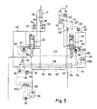
- a third selector valve 136 is disposed downstream of the load-detecting flow passage 68, specifically the connecting part of the flow passage 132 and the pilot pressure taking part of the pressure reducing valve 124, and adapted to be selectively held at a communicating position (the position shown in Figure 2) at which it communicates with the load-detecting flow passage 68 and a shutting position (the position shown in Figure 3) at which it shuts off the load-detecting flow passage 68 (in the illustrated embodiment, the selector valve 136 at the shutting position permits the downstream portion of the load detecting flow passage 68, i.e. that portion of the flow passage 68 which is downstream of the third selector valve 136, to communicate with the return flow passage 40 via part of the flow passage 104).
- the pilot flow passage 118 is connected to the third selector valve 136, and therefore when the pilot pressure Pb in the pilot flow passage 118 increases, the third selector valve 118 is brought to the shutting position from the communicating position.
- the pilot flow passage 116 instead of the pilot flow passage 118, may be connected to the third selector valve 136.
- the boom 10 may be actuated upwardly (or downwardly) by operating the pilot valve 98 to exert the pilot pressure Pb (or the pilot pressure Pa) on the first selector valve 22 and holding the first selector valve 22 at the second operative position (or the first operative position) (the relation between the stroke of the operating lever of the remote control valve 98 and the pilot pressures Pa and Pb is as shown in Figure 4).
- the feed flow passage 38 communicates with the second flow passage 28 (or the first flow passage 26) via the first selector valve 22, the fifth flow passage 60 and the first flow control valve 22 and the first flow passage 26 (or the second flow passage 28 communicates with the return flow passage 40 via the first selector valve 22.
- the fluid supplied from the variable displacement pump 36 is fed to the extending side (or the retracting side) of the fluid pressure cylinder mechanism 12 through the second flow passage 28 (or the first flow passage 26).
- the fluid in the retracting side (or the extending side) of the fluid pressure cylinder mechanism 12 is returned to the return flow passage 40 through the first flow passage 26 (or the second flow passage 28).
- the fluid pressure cylinder mechanism 12 is extended (or retracted).
- the first selector valve 22 includes a plurality of orifices, and the fluid fed to the fifth flow passage 60 at the first and second operative positions and the fluid returned to the return flow passage 40 at the first operative position are affected by orifices.
- the fluid pressure in the load-detecting flow passage 66 of the first selector valve 22 is transmitted to the main load-detecting flow passage 64 via the shuttle valve 74 and the flow passage 78.
- the fluid fed to the load-detecting flow passage 66 is also affected by the orifices.
- the upper swing frame 6 ( Figure 1) may swing in a predetermined direction (for example, a right direction or a opposite direction) by operating the pilot valve 100 to apply the pilot pressure Pc (or the pilot pressure Pd) on the second selector valve 24 and holding the second selector valve 24 at the first operative position (or the second operative position) (the relation between the stroke of the operating lever of the remote control valve and the pilot pressures Pc and Pd is as shown in Figure 4).
- a predetermined direction for example, a right direction or a opposite direction
- the feed flow passage 38 communicates with the third flow passage 30 (or the fourth flow passage 32) via the second selector valve 24, the sixth flow passage 62, the second flow control valve 58 and the pressure reducing valve 124, and the fourth flow passage 32 (or the third flow passage 30) communicates with the return flow passage 40 via the second selector valve 24.
- the fluid fed from the variable displacement pump 36 is fed to the fluid pressure motor 8 through the third flow passage 30 (or the fourth flow passage 32), and the fluid in the fluid pressure motor 8 is returned to the return flow passage 40 through the fourth flow passage (or the third flow passage 30).
- the fluid pressure motor 8 is rotated in a predetermined direction (or a direction opposite to the predetermined direction).
- the second selector valve 24 includes a plurality of orifices and check valves 160 and 162, and the second flow rate control valve 58 also includes an orifice. Accordingly, the fluid fed to the sixth flow passage 62 at the first and second operative positions is affected by the orifices of the second selector valve 24, and the fluid fed to the pressure reducing valve 124 is affected by the orifice of the second flow rate control valve 58.
- the second selector valve 24 is at the first and second positions, the reverse flowing of the fluid from the third flow passage 30 to the sixth flow passage 62 and the reverse flowing of the fluid from the fourth flow passage 32 to the sixth flow passage 62 are exactly blocked by the check valves 160 and 162.
- the fluid pressure in the load-detecting flow passage 68 of the second selector valve 24 is transmitted to the main load-detecting flow passage 64 via the third selector valve 136, the shuttle valve 74 and the flow passage 78.
- the fluid fed to the load-detecting flow passage 69 is also affected by a throttling action.
- the illustrated fluid pressure control system further has the following characteristic feature.
- the control valve 58 When the fluid pressure of the primary side of the second flow control valve 58 is so elevated, the control valve 58 is at an open position and opens the sixth flow passage 62 to a maximum. the fluid pressure on the outlet side of the second flow control valve 58 is also elevated to the discharge pressure of the variable displacement pump 36. As a result, the discharge pressure is transmitted to the main load-detecting flow passage 64 via the load-detecting flow passage 69 and the check valve 164, and the cylinder 82 is moved to the amount increasing side shown by arrow 92. The amount of discharge from the variable displacement pump 36 thus increases.
- the pressure reducing valve 124 and the relief valve 126 are provided, the fine-controllability of the upper swing frame 6 can be markedly enhanced.
- the pilot pressure Pc or the pilot pressure Pd which ever is higher, is transmitted to the large chamber 126a of the relief valve 126 via the shuttle 128 and the flow passage 130.
- the fluid pressure in the load-detecting flow passage 68 or in other words, in the third flow passage 30 (or the fourth flow passage 32) is transmitted to the small chamber 126b of the relief valve 126 via the orifices and the flow passage 132, and the pressure transmitted to the relief valve 126 acts as a pilot pressure on the pressure reducing valve 124. Accordingly, if the pilot pressure Pc (or the pilot pressure Pd) is high, the pressure acting on the large chamber 126a of the relief valve 126 also becomes high. As a result, the relief valve 126 becomes difficult of opening and the fluid pressure in the load-detecting flow passage 68 is elevated.
- the pressure acting on the large chamber 126a of the relief valve 126 also becomes low.
- the relief valve 126 can be opened even with a relatively low pressure from the flow passage 132, and the elevation of the fluid pressure in the load-detecting flow passage 68 is circumvented.
- the fluid pressure on the outlet side of the pressure reducing valve 124 is affected by the fluid pressure in the load-detecting flow passage 68 acting as a pilot pressure and becomes lower than a pressure varying in a straight line in substantial proportion to the pilot pressure Pc(or the pilot pressure Pd) as shown by a solid line in Figure 5.
- Figure 5 shows the relation between the stroke of the pilot valve 100 and the maximum fluid pressure on the outlet side of the pressure reducing valve 124.
- the pressure P1 is a fluid pressure determined by the pressure of the spring 126c of the relief valve 126 and the pressure of the spring 124a of the pressure reducing valve 124
- the pressure P2 is a pressure set by the relief valve 52 (or the relief valve 54). Accordingly, even if the output shaft of the fluid pressure motor is restrained by some external load. the action of the pressure reducing valve 124 suppresses the elevation of the fluid pressure (the pressure on the outlet side of the pressure reducing valve 124) fed to the fluid pressure motor 8. As a result, the output shaft of the fluid pressure motor 8 is not rotated with a strong torque as in the prior art, and the upper swing frame 6 can be micro-operated finely as is desired.
- the feed flow passage 38 communicates with the first flow passage 26 via the first selector valve 22, the fifth flow passage 60 and the first flow control valve 56 and the second flow passage 28 communicates with the return flow passage 40 via the first selector valve 22. Furthermore, the feed flow passage 38 communicates with the third flow passage (or the fourth flow passage 32) via the second selector valve 24, the sixth flow passage 62, the second flow control valve 58 and the pressure reducing valve 124, and the fourth flow passage 32 (or the third flow passage 30) communicates with the return flow passage 40 via the second selector valve 24.
- the fluid from the variable displacement pump 36 is fed to the rod side of the fluid pressure cylinder mechanism 12 via the first flow passage 26 and the fluid on the head side of the cylinder mechanism 12 is returned to the return flow passage via the second flow passage 28.
- the fluid pressure cylinder mechanism 12 is retracted as is required.
- the fluid from the variable delivery pump 36 is fed to the fluid pressure motor 8 via the third flow passage 30 (or the fourth flow passage 32), and the fluid of the fluid pressure motor 8 is returned to the return flow passage 40 via the fourth flow passage 32 (or the third flow passage 30).
- the fluid pressure motor 8 is rotated in a predetermined direction (or a direction opposite to the predetermined direction).
- the fluid pressure described below acts on the main load-detecting flow passage 64.
- the third selector valve 136 since the third selector valve 136 is at the communicating position, the fluid pressure in the load-detecting flow passage 66 of the first selector valve 22 acts on one side of the shuttle valve 74, and the fluid pressure in the load-detecting flow passage 68 of the second selector valve 24 acts on the other side of the shuttle valve 74 via the third selector valve 136.
- the shuttle valve 74 transmits the fluid pressure in the load-detecting flow passage 66 or the fluid pressure in the load-detecting flow passage 68, whichever is higher, to the main load-detecting flow passage 64.
- the feed flow passage 38 communicates with the second flow passage 28 via the first selector valve 22
- the fifth flow passage 60 and the first flow control valve 56 and the first flow passage 26 communicates with the return flow passage 40 via the first selector valve 22
- further the feed flow passage 38 communicates with the fourth flow passage 32 (or the third flow passage 30) via the second selector valve 24, the sixth flow passage 62, the second flow control valve 58 and the pressure reducing valve 124 and also the third flow passage 30 (or the fourth flow passage 32) communicates with the return flow passage 40 via the second selector valve 24, as shown in Figure 3 ( Figure 3 only shows the case where the second selector valve 24 is at the second operative position).
- the fluid from the variable displacement pump 36 is fed to the head side of the fluid pressure cylinder mechanism 12 via the second flow passage 28 and the fluid in the rod side of the fluid pressure cylinder mechanism 12 is returned to the return flow passage 40 via the first flow passage 26.
- the fluid pressure cylinder mechanism 12 is extended as is required.
- the fluid from the variable displacement pump 36 is fed to the fluid pressure motor 8 via the fourth flow passage 32 (or the third flow passage 30) and the fluid of the fluid pressure motor 8 is returned to the return flow passage 40 via the third flow passage 30 (or the fourth flow passage 32).
- the fluid pressure motor 8 is thus rotated in a direction opposite to the predetermined direction (or in the predetermined direction).
- the pilot valve 98 When in order to hold the first selector valve 22 at the second operative position, the pilot valve 98 is operated to elevate the pilot pressure Pb (specifically, the pilot pressure Pb exceeds a preset pressure of the spring 136a of the third selector valve 136), the action of the pilot pressure Pb brings the third selector valve 136 to the shutting position from the communicating position. As a result, the load-detecting flow passage 68 of the second selector valve 24 is shut off, and the other side of the shuttle valve 74 is connected to the return flow passage 40 via the third selector valve 136. The fluid pressure of the load-detecting flow passage 66 of the first selector valve 22 is transmitted to the main load-detecting flow passage 64 via the shuttle valve 74 and the flow passage 78.
- the fluid pressure control system in the illustrated embodiment also has the following characteristic feature.
- the fluid pressure fed to the fluid pressure motor 8 from the second flow control valve 58 reaches a pressure preset in the relief valve 52 (or 54).
- the fluid pressure fed to the head side of the fluid pressure cylinder mechanism 12 which corresponds to the force to lift the boom 10 is usually lower than the pressure preset at the relief valve 52 (or 54).
- the fluid pressure in the load-detecting flow passage 68 of the second selector valve 24′ is transmitted to the main load-detecting flow passage 64 via the check valve 154, and the fluid pressure motor 8 is driven by the pressure set at the relief valve 52 (or 54). Accordingly, the rotating torque of the fluid pressure motor 8 is high, and the swinging speed of the upper swing frame 6 after a predetermined period of time becomes much faster than the raising speed of the boom 10.
- the third selector valve 136 is disposed in the load-detecting flow passage 58 of the second selector valve 24, and is held at the shutting position by the pilot pressure Pb at the time of full operation of lifting the boom 10 ( Figure 1).
- the main load-detecting flow passage 64 is not at all affected by the fluid pressure in the load-detecting flow passage 68 of the second selector valve 24 but is affected by the fluid pressure in the main load-detecting flow passage 66 of the first selector valve 22.
- the discharge pressure of the variable displacement pump 36 equals the sum of the fluid pressure of the main load-detecting flow passage 64 (therefore, the fluid pressure of the head side of the fluid pressure cylinder mechanism 12) and the pressure of the spring 80a of the selector valve 80.
- the pressure of the spring 80a is low, and the discharge pressure of the pump 36 is lower than the pressure set at the relief valve 52 (or 54).
- the pilot valve 100 when the pilot valve 100 is fully operated, the upper limit of the fluid pressure on the outlet side of the pressure reducing valve 112 is close to, or higher than, the pressure set at the relief valve 52 (or 54), as shown in Figure 5.
- the fluid from the variable displacement pump is not substantially affected by the pressure reducing valve 124, and is fed to the third flow passage 30 (or the fourth flow passage 32) through the pressure reducing valve 124.
- the pressure of the fluid fed to the fluid pressure motor 8 is lower than in the conventional system, and the swinging speed of the upper swing frame 6 becomes lower than in the conventional system.
- the relation between the swinging angle of the upper swing frame 6 and the raising position of the end portion of the boom 10 forms the locus shown by solid line B in Figure 6 which is a relatively high curve. Accordingly, the elevation of the boom 10 and the swinging of the upper swing frame 6 can be performed as the operator intends, and collision of the bucket 18 with a low structure, etc. during the swinging of the upper swing frame 6 can be circumvented.
Landscapes
- Engineering & Computer Science (AREA)
- General Engineering & Computer Science (AREA)
- Mining & Mineral Resources (AREA)
- Civil Engineering (AREA)
- Structural Engineering (AREA)
- Physics & Mathematics (AREA)
- Fluid Mechanics (AREA)
- Mechanical Engineering (AREA)
- Operation Control Of Excavators (AREA)
- Fluid-Pressure Circuits (AREA)
Claims (11)
- Fluiddruck-Steuersystem, das aufweist
eine Verstellpumpe (36), deren Fördermenge verstellbar ist,
ein erstes Wahlventil (22), das so ausgebildet ist, daß es selektiv in einer Neutralstellung, einer ersten Arbeitsstellung und einer zweiten Arbeitsstellung gehalten wird,
ein zweites Wahlventil (24), das so ausgebildet ist, daß es selektiv in einer Neutralstellung, einer ersten Arbeitsstellung und einer zweiten Arbeitsstellung gehalten wird,
eine erste Stelleinheit (12), deren Betrieb durch die Verschiebung des ersten Wahlventils (22) zu steuern ist,
eine zweite Stelleinheit (8), deren Betrieb durch die Verschiebung des zweiten Wahlventils (24) zu steuern ist,
ein erstes Durchflußregelventil (56) zum Regeln eines der ersten Stelleinheit (12) zuzuführenden Fluids,
ein zweites Durchflußregelventil (58) zum Regeln eines der zweiten Stelleinheit (8) zuzuführenden Fluids,
eine Speisestromleitung (38), die die Verstellpumpe (36) mit dem ersten und dem zweiten Wahlventil (22, 24) verbindet,
eine Rückstromleitung (40), die mit dem ersten und dem zweiten Wahlventil (22, 24) verbunden ist,
eine erste und eine zweite Strömungsleitung (26, 28), die das erste Wahlventil (22) mit der ersten Stelleinheit (12) verbinden,
eine dritte und eine vierte Strömungsleitung (30, 32), die das zweite Wahlventil (24) mit der zweiten Stelleinheit (8) verbinden, und
eine Lasterfassungs-Hauptdurchflußleitung (64) zum Steuern der Fördermenge der Verstellpumpe (36),
wobei das erste Wahlventil (22) in der ersten Arbeitsstellung eine Verbindung der Speiseleitung (38) mit der ersten Strömungsleitung (26) sowie der Rückstromleitung (40) mit der zweiten Strömungsleitung (28) zuläßt,
das erste Wahlventil (22) in der zweiten Arbeitsstellung eine Verbindung der Speiseleitung (38) mit der zweiten Strömungsleitung (28) sowie der Rückstromleitung (40) mit der ersten Strömungsleitung (30) zuläßt,
das erste Wahlventil (22) in der Neutralstellung die Verbindung der Speisestromleitung (38) und der Rückstromleitung (40) mit der ersten Strömungsleitung (26) und der zweiten Strömungsleitung (28) absperrt,
das zweite Wahlventil (24) in der ersten Arbeitsstellung eine Verbindung der Speiseleitung (38) mit der dritten Strömungsleitung (30) sowie der Rückstromleitung (40) mit der vierten Strömungsleitung (32) zuläßt,
das zweite Wahlventil (24) in der zweiten Arbeitsstellung eine Verbindung der Speiseleitung (38) mit der vierten Strömungsleitung (32) sowie der Rückstromleitung (40) mit der dritten Strömungsleitung (30) zuläßt,
das zweite Wahlventil (24) in der Neutralstellung die Verbindung der Speisestromleitung (38) und der Rückstromleitung (40) mit der dritten Strömungsleitung (30) und der vierten Strömungsleitung (32) absperrt,
das erste Durchflußregelventil (56) so ausgebildet ist, daß es ein von der Speisestromleitung (38) der ersten (26) oder der zweiten (28) Strömungsleitung zuzuführendes Fluid regelt, wenn das erste Wahlventil (22) die erste oder die zweite Arbeitsstellung hat, und
das zweite Durchflußregelventil (58) so ausgebildet ist, daß es ein von dem Speisestromleitung (38) der dritten (30) oder der vierten (32) Strömungsleitung zuzuführendes Fluid regelt, wenn das zweite Wahlventil (24) die erste oder die zweite Arbeitsstellung hat;
dadurch gekennzeichnet, daß
ein Druckminderventil (124) und ein Entlastungsventil (126) relativ zu dem zweiten Durchflußregelventil (58) angeordnet sind, das Druckminderventil (124) den Druck des der zweiten Stelleinheit (8) durch das zweite Wahlventil (24) zugeführten Fluids mindert und der Druck an der Auslaßseite des Druckminderventils (124) durch den Betrieb des durch einen externen Steuerdruck gesteuerten Entlastungsventils (126) gesteuert wird. - Fluiddruck-Steuersystem nach Anspruch 1, bei dem das Entlastungsventil (126) zwischen der Rückstromleitung (40) und einer Lasterfassungs-Durchflußleitung (68) in dem zweiten Wahlventil (24) angeordnet ist.
- Fluiddruck-Steuersystem nach Anspruch 2, bei dem der Betrieb des zweiten Wahlventils (24) durch einen ersten Steuerdruck (Pc) und einen zweiten Steuerdruck (Pd) gesteuert wird und der jeweils höhere des ersten und des zweiten Steuerdrucks auf eine Federkammer in dem Entlastungsventil (126) einwirkt.
- Fluiddruck-Steuersystem nach Anspruch 3, bei dem das Entlastungsventil ein Proportionaldruckentlastungsventil (126) ist, das das Verhältnis des Drucks in der Lasterfassungs-Durchflußleitung (68) des zweiten Wahlventils (24) zu dem auf die Federkammer einwirkenden Steuerdruck auf einen vorbestimmten Wert einstellt.
- Fluiddruck-Steuersystem nach Anspruch 2, bei dem der Fluiddruck in der Lasterfassungs-Durchflußleitung (68) des zweiten Wahlventils (24) auf das Druckminderventil (124) als Steuerdruck wirkt.
- Fluiddruck-Steuersystem nach Anspruch 5, bei dem das Druckminderventil ein Proportionaldruckminderventil (124) ist, das den primärseitigen Fluiddruck aufgrund des Steuerdrucks mindert.
- Fluiddruck-Steuersystem nach Anspruch 1, bei dem eine Lasterfassungs-Durchflußleitung (66) in dem ersten Wahlventil (22) und eine Lasterfassungs-Durchflußleitung (68) in dem zweiten Wahlventil (24) durch ein Wechselventil (74) mit der Lasterfassungs-Hauptdurchflußleitung (64) verbunden sind und der jeweils höhere des Fluiddrucks in der Lasterfassungs-Durchflußleitung (66) des ersten Wahlventils (22) und des Fluiddrucks in der Lasterfassungs-Durchflußleitung (68) des zweiten Wahlventils (24) durch das Wechselventil (74) zu der Lasterfassungs-Hauptdurchflußleitung (68) übertragen wird.
- Fluiddruck-Steuersystem nach Anspruch 7, bei dem ein drittes Wahlventil (136) in der Lasterfassungs-Durchflußleitung (68) des zweiten Wahlventils (24) angeordnet und das dritte Wahlventil (136) so ausgebildet ist, daß es selektiv in einer Verbindungsstellung, in der es eine Verbindung mit der Lasterfassungs-Durchflußleitung (68) herstellt, oder in einer Absperrstellung gehalten wird, in der es die Lasterfassungs-Durchflußleitung (68) absperrt.
- Fluiddruck-Steuersystem nach Anspruch 8, bei dem das dritte Wahlventil (136) so ausgebildet ist, daß es in der Absperrstellung gehalten wird, wenn das erste Wahlventil (22) in der ersten oder der zweiten Arbeitsstellung gehalten wird.
- Fluiddruck-Steuersystem nach Anspruch 9, bei dem der Betrieb des ersten Wahlventils (22) durch einen externen Steuerdruck gesteuert und das dritte Wahlventil (136) durch den externen Steuerdruck in der Absperrstellung gehalten wird.
- Fluiddruck-Steuersystem nach Anspruch 1, bei dem die erste Stelleinheit ein Fluiddruckzylindermechanismus (12) ist, der einen Ausleger (10) eines Hydraulikbaggers vertikal schwenkt und die zweite Stelleinheit ein Fluiddruckmotor (8) zum Verschwenken eines oberen Schwenkrahmens (6) des Hydraulikbaggers ist.
Applications Claiming Priority (2)
| Application Number | Priority Date | Filing Date | Title |
|---|---|---|---|
| JP62242744A JP2582266B2 (ja) | 1987-09-29 | 1987-09-29 | 流体圧制御システム |
| JP242744/87 | 1987-09-29 |
Publications (2)
| Publication Number | Publication Date |
|---|---|
| EP0309987A1 EP0309987A1 (de) | 1989-04-05 |
| EP0309987B1 true EP0309987B1 (de) | 1992-04-22 |
Family
ID=17093612
Family Applications (1)
| Application Number | Title | Priority Date | Filing Date |
|---|---|---|---|
| EP88115881A Expired EP0309987B1 (de) | 1987-09-29 | 1988-09-27 | Steuersystem für einen unter Druck stehenden Flüssigkeitskreislauf |
Country Status (5)
| Country | Link |
|---|---|
| US (1) | US4938023A (de) |
| EP (1) | EP0309987B1 (de) |
| JP (1) | JP2582266B2 (de) |
| CA (1) | CA1299064C (de) |
| DE (1) | DE3870381D1 (de) |
Cited By (1)
| Publication number | Priority date | Publication date | Assignee | Title |
|---|---|---|---|---|
| DE4235707B4 (de) * | 1992-10-22 | 2007-10-18 | Linde Material Handling Gmbh | Hydrostatisches Antriebssystem |
Families Citing this family (48)
| Publication number | Priority date | Publication date | Assignee | Title |
|---|---|---|---|---|
| US5186000A (en) * | 1988-05-10 | 1993-02-16 | Hitachi Construction Machinery Co., Ltd. | Hydraulic drive system for construction machines |
| WO1989011041A1 (fr) * | 1988-05-10 | 1989-11-16 | Hitachi Construction Machinery Co., Ltd. | Unite d'entrainement hydraulique pour engin de construction |
| JP2784188B2 (ja) * | 1988-07-18 | 1998-08-06 | 日立建機株式会社 | 油圧駆動装置 |
| US5048293A (en) * | 1988-12-29 | 1991-09-17 | Hitachi Construction Machinery Co., Ltd. | Pump controlling apparatus for construction machine |
| US5101629A (en) * | 1989-02-20 | 1992-04-07 | Hitachi Construction Machinery Co., Ltd. | Hydraulic circuit system for working machine |
| US5063742A (en) * | 1989-07-26 | 1991-11-12 | Kabushiki Kaisha Kobe Seiko Sho | Method of controlling swing motion of a revolving superstructure and hydraulic control system for carrying out same |
| US5046311A (en) * | 1989-12-14 | 1991-09-10 | Cartner Jack O | Hydraulic control system |
| US5046309A (en) * | 1990-01-22 | 1991-09-10 | Shin Caterpillar Mitsubishi Ltd. | Energy regenerative circuit in a hydraulic apparatus |
| JP2864667B2 (ja) * | 1990-06-04 | 1999-03-03 | 株式会社豊田自動織機製作所 | 産業車両の油圧装置 |
| JP2600009B2 (ja) * | 1990-04-25 | 1997-04-16 | 株式会社神戸製鋼所 | クレーンの旋回制御装置 |
| US5271227A (en) * | 1990-05-15 | 1993-12-21 | Kabushiki Kaisha Komatsu Seisakusho | Hydraulic apparatus with pressure compensating valves |
| WO1992006306A1 (fr) * | 1990-09-28 | 1992-04-16 | Hitachi Construction Machinery Co., Ltd. | Systeme de commande pour pompe hydraulique |
| GB2251232B (en) * | 1990-09-29 | 1995-01-04 | Samsung Heavy Ind | Automatic actuating system for actuators of excavator |
| JPH04173433A (ja) * | 1990-11-06 | 1992-06-22 | Toyota Autom Loom Works Ltd | 車両用油圧システム |
| GB2250611B (en) * | 1990-11-24 | 1995-05-17 | Samsung Heavy Ind | System for automatically controlling quantity of hydraulic fluid of an excavator |
| DE69128882T3 (de) * | 1990-11-26 | 2002-04-25 | Hitachi Construction Machinery Co., Ltd. | Hydraulisches Steuersystem und Richtungsumschaltventile |
| JP3195989B2 (ja) * | 1990-12-31 | 2001-08-06 | 帝人製機株式会社 | クローラ車両走行油圧回路 |
| US5241821A (en) * | 1991-04-08 | 1993-09-07 | Kabushiki Kaisha Toyoda Jidoshokki Seisakusho | Hydraulic system for a vehicle |
| JP3101830B2 (ja) * | 1991-06-12 | 2000-10-23 | 株式会社小松製作所 | 旋回式作業装置の油圧回路 |
| DE4140423A1 (de) * | 1991-12-07 | 1993-06-09 | Mannesmann Rexroth Gmbh, 8770 Lohr, De | Vorrichtung zur einstellung des arbeitsfluessigkeitsdruckes |
| JP3124094B2 (ja) * | 1991-12-25 | 2001-01-15 | カヤバ工業株式会社 | 複数アクチュエータの制御装置 |
| US5193342A (en) * | 1992-02-14 | 1993-03-16 | Applied Power Inc. | Proportional speed control of fluid power devices |
| JPH0586002U (ja) * | 1992-04-24 | 1993-11-19 | 株式会社小松製作所 | 圧力補償弁を有する油圧回路の最高負荷圧検出回路 |
| DE4235709A1 (de) * | 1992-10-22 | 1994-04-28 | Linde Ag | Hydrostatisches Antriebssystem |
| DE4311191C2 (de) * | 1993-04-05 | 1995-02-02 | Deere & Co | Hydrauliksystem zur Versorgung offener oder geschlossener Hydraulikfunktionen |
| US5538149A (en) * | 1993-08-09 | 1996-07-23 | Altec Industries, Inc. | Control systems for the lifting moment of vehicle mounted booms |
| JP3477687B2 (ja) * | 1993-11-08 | 2003-12-10 | 日立建機株式会社 | 流量制御装置 |
| DE4417962A1 (de) * | 1994-05-21 | 1995-11-23 | Rexroth Mannesmann Gmbh | Steueranordnung für wenigstens zwei hydraulische Verbraucher |
| KR0149708B1 (ko) * | 1994-07-25 | 1998-10-15 | 석진철 | 선회 토르크 제어장치 |
| KR970011608B1 (ko) * | 1994-09-06 | 1997-07-12 | 대우중공업 주식회사 | 건설기계의 선회토르크 제어장치(an apparatus for controlling turning torque in a construction equipment) |
| KR100212646B1 (ko) * | 1994-10-29 | 1999-08-02 | 토니헬샴 | 액츄에이터 조작신호 감지장치 |
| US6216456B1 (en) * | 1999-11-15 | 2001-04-17 | Caterpillar Inc. | Load sensing hydraulic control system for variable displacement pump |
| DE10058032A1 (de) * | 2000-11-23 | 2002-05-29 | Mannesmann Rexroth Ag | Hydraulische Steueranordnung |
| US7610989B2 (en) * | 2002-05-29 | 2009-11-03 | Volvo Construction Equipment Ab | Control system and a vehicle comprising the control system |
| US6662558B1 (en) * | 2002-07-02 | 2003-12-16 | Caterpillar Inc | Variable delivery control arrangement for a pump |
| US7260931B2 (en) * | 2005-11-28 | 2007-08-28 | Caterpillar Inc. | Multi-actuator pressure-based flow control system |
| KR101391850B1 (ko) * | 2006-10-12 | 2014-05-07 | 볼보 컴팩트 이키프먼트 에스에이에스 | 유압제어 선택시스템을 구비한 건설기계 |
| US9109345B2 (en) * | 2009-03-06 | 2015-08-18 | Komatsu Ltd. | Construction machine, method for controlling construction machine, and program for causing computer to execute the method |
| US9051714B2 (en) * | 2011-09-30 | 2015-06-09 | Caterpillar Inc. | Meterless hydraulic system having multi-actuator circuit |
| DE102012218428B4 (de) * | 2012-10-10 | 2025-10-09 | Robert Bosch Gmbh | Open-Center-Ventilblock mit zwei Pumpenanschlüssen und zugeordneten Hilfsschiebern an den Hauptschiebern |
| CN103924626B (zh) * | 2014-04-02 | 2016-04-13 | 华侨大学 | 电驱动液压挖掘机的节能型转台驱动系统及驱动控制方法 |
| EP3018364B1 (de) * | 2014-11-10 | 2017-08-16 | HAWE Hydraulik SE | Steuervorrichtung mit Schieberkolben |
| DE102015122915A1 (de) | 2015-12-29 | 2017-06-29 | Xcmg European Research Center Gmbh | Hydraulische Steuerung |
| IT201800009591A1 (it) * | 2018-10-18 | 2020-04-18 | Walvoil Spa | Sistema idraulico di tipo load sensing con dispositivo idraulico di regolazione |
| CN110329912B (zh) * | 2019-07-17 | 2020-07-24 | 北汽福田汽车股份有限公司 | 起重机控制系统及具有其的起重机 |
| CN110762075B (zh) * | 2019-10-28 | 2021-11-23 | 雷沃工程机械集团有限公司 | 一种基于改进型液压转向旁通优先阀的转向系统及方法 |
| CN110848185B (zh) * | 2019-11-11 | 2021-11-23 | 雷沃工程机械集团有限公司 | 一种轮式工程机械液压控制系统及方法 |
| CN114319475B (zh) * | 2021-12-31 | 2023-05-23 | 潍柴动力股份有限公司 | 一种动臂控制阀结构及挖机 |
Family Cites Families (16)
| Publication number | Priority date | Publication date | Assignee | Title |
|---|---|---|---|---|
| DE2052303A1 (de) * | 1970-10-24 | 1972-04-27 | Rheinstahl Aktiengesellschaft Hanomag Baumaschinen, 3000 Hannover-Linden | Hydraulikanlage für Planiermaschinen, Lademaschinen, Bagger und dergl |
| GB2081394B (en) * | 1980-05-30 | 1983-12-07 | Komatsu Mfg Co Ltd | Hydraulic systems |
| US4523430A (en) * | 1981-03-19 | 1985-06-18 | Daikin Kogyo Co., Ltd. | Fluid flow control system |
| US4573319A (en) * | 1981-08-10 | 1986-03-04 | Clark Equipment Company | Vehicle hydraulic system with single pump |
| US4365429A (en) * | 1981-11-18 | 1982-12-28 | Bucyrus-Erie Company | Maximum lift system for hydraulic hoe |
| JPS58174707A (ja) * | 1982-04-06 | 1983-10-13 | Daiden Kk | 複数機器油圧駆動回路 |
| JPS5943202A (ja) * | 1982-09-02 | 1984-03-10 | Kayaba Ind Co Ltd | 油圧制御回路 |
| JPS5943203A (ja) * | 1982-09-03 | 1984-03-10 | Kayaba Ind Co Ltd | 油圧制御回路 |
| JPS5954801A (ja) * | 1982-09-21 | 1984-03-29 | Kayaba Ind Co Ltd | 油圧制御回路 |
| AU1928283A (en) * | 1982-11-26 | 1984-05-31 | Vickers Incorporated | Power transmission |
| US4665698A (en) * | 1983-04-18 | 1987-05-19 | Clark Equipment Company | Hydraulic system with proportional control |
| IT1234937B (it) * | 1985-02-14 | 1992-06-02 | Cinotto Hydraulic | Sistema antisaturazione per circuiti idraulici di comando con pompe e distributori compensati in pressione per organi di lavoro di macchine movimento terra |
| DE3532816A1 (de) * | 1985-09-13 | 1987-03-26 | Rexroth Mannesmann Gmbh | Steueranordnung fuer mindestens zwei von mindestens einer pumpe gespeiste hydraulische verbraucher |
| DE3535771A1 (de) * | 1985-10-07 | 1987-04-09 | Linde Ag | Hydrostatischer antrieb mit mehreren verbrauchern |
| IT1187892B (it) * | 1986-02-04 | 1987-12-23 | Chs Vickers Spa | Circuito idraulico di comando per organi di lavoro di macchine movimento terra con frenatura centralizzata degli attuatori |
| JP6158682B2 (ja) | 2013-10-25 | 2017-07-05 | エスアイアイ・セミコンダクタ株式会社 | 磁気センサ回路 |
-
1987
- 1987-09-29 JP JP62242744A patent/JP2582266B2/ja not_active Expired - Fee Related
-
1988
- 1988-09-15 US US07/245,049 patent/US4938023A/en not_active Expired - Fee Related
- 1988-09-26 CA CA000578445A patent/CA1299064C/en not_active Expired - Fee Related
- 1988-09-27 DE DE8888115881T patent/DE3870381D1/de not_active Expired - Fee Related
- 1988-09-27 EP EP88115881A patent/EP0309987B1/de not_active Expired
Cited By (1)
| Publication number | Priority date | Publication date | Assignee | Title |
|---|---|---|---|---|
| DE4235707B4 (de) * | 1992-10-22 | 2007-10-18 | Linde Material Handling Gmbh | Hydrostatisches Antriebssystem |
Also Published As
| Publication number | Publication date |
|---|---|
| US4938023A (en) | 1990-07-03 |
| JPS6487901A (en) | 1989-04-03 |
| JP2582266B2 (ja) | 1997-02-19 |
| DE3870381D1 (de) | 1992-05-27 |
| CA1299064C (en) | 1992-04-21 |
| EP0309987A1 (de) | 1989-04-05 |
Similar Documents
| Publication | Publication Date | Title |
|---|---|---|
| EP0309987B1 (de) | Steuersystem für einen unter Druck stehenden Flüssigkeitskreislauf | |
| EP1532065B1 (de) | Steuersystem für eine lasthandhabungsvorrichtung | |
| JP3916559B2 (ja) | 圧力補償型流量制御装置を備えた油圧制御バルブシステム | |
| US8504251B2 (en) | Interference prevention control device of a machine | |
| JPH05196005A (ja) | 作業用具制御装置および方法 | |
| DE19532769A1 (de) | Fluiddrucksteuerungssystem für Hydraulikbagger | |
| EP0006117B1 (de) | Durch Lastdruck bediente Geschwindigkeitssteuerung bei einem Hydraulikmotor | |
| US6450081B1 (en) | Hydraulic system for controlling an attachment to a work machine such as thumb attachment used on an excavator | |
| US4338856A (en) | Dual pilot counterbalance valve | |
| EP0652377A1 (de) | Ventilregeleinrichtung für hydraulische Stellorgane | |
| US4669363A (en) | Hydraulic priority control means for at least two servo motors | |
| US7080590B2 (en) | Valve arrangement and hydraulic drive | |
| EP2029815B1 (de) | Verfahren zur lagegerechten ausrichtung einer an einem heb- und senkbaren hubgerüst einer arbeitsmaschine kippbar angeordneten arbeitsausrüstung | |
| JPS6083505A (ja) | トラクタ用作業機の昇降制御装置 | |
| KR100342109B1 (ko) | 위치와 적용되는 힘에 대하여 제어 가능한, 트랙터 및 농업용 기계에 대한 유압식 호이스트 및 이러한 호이스트용 디스트리뷰터 | |
| US5606901A (en) | Hydraulic circuit for turning purposes | |
| KR0169880B1 (ko) | 굴삭기의 붐 상승속도 및 선회속도 조절장치 | |
| EP1188709B1 (de) | Hubvorrichtung | |
| JPH0446491Y2 (de) | ||
| JP2007106564A (ja) | キャブ昇降装置 | |
| JPH04179698A (ja) | バッテリ式産業車両における油圧装置 | |
| JP2572152Y2 (ja) | 作業用走行車の油圧昇降装置 | |
| JP2607939B2 (ja) | 乗用トラクタにおける油圧装置 | |
| WO2006110068A1 (en) | Mobile handling device | |
| JP4081209B2 (ja) | 緩速下降装置 |
Legal Events
| Date | Code | Title | Description |
|---|---|---|---|
| PUAI | Public reference made under article 153(3) epc to a published international application that has entered the european phase |
Free format text: ORIGINAL CODE: 0009012 |
|
| AK | Designated contracting states |
Kind code of ref document: A1 Designated state(s): DE FR |
|
| 17P | Request for examination filed |
Effective date: 19890914 |
|
| 17Q | First examination report despatched |
Effective date: 19910115 |
|
| GRAA | (expected) grant |
Free format text: ORIGINAL CODE: 0009210 |
|
| AK | Designated contracting states |
Kind code of ref document: B1 Designated state(s): DE FR |
|
| ET | Fr: translation filed | ||
| REF | Corresponds to: |
Ref document number: 3870381 Country of ref document: DE Date of ref document: 19920527 |
|
| PLBE | No opposition filed within time limit |
Free format text: ORIGINAL CODE: 0009261 |
|
| STAA | Information on the status of an ep patent application or granted ep patent |
Free format text: STATUS: NO OPPOSITION FILED WITHIN TIME LIMIT |
|
| 26N | No opposition filed | ||
| PGFP | Annual fee paid to national office [announced via postgrant information from national office to epo] |
Ref country code: FR Payment date: 20020910 Year of fee payment: 15 |
|
| PGFP | Annual fee paid to national office [announced via postgrant information from national office to epo] |
Ref country code: DE Payment date: 20021002 Year of fee payment: 15 |
|
| PG25 | Lapsed in a contracting state [announced via postgrant information from national office to epo] |
Ref country code: DE Free format text: LAPSE BECAUSE OF NON-PAYMENT OF DUE FEES Effective date: 20040401 |
|
| PG25 | Lapsed in a contracting state [announced via postgrant information from national office to epo] |
Ref country code: FR Free format text: LAPSE BECAUSE OF NON-PAYMENT OF DUE FEES Effective date: 20040528 |
|
| REG | Reference to a national code |
Ref country code: FR Ref legal event code: ST |