EP0309539B1 - Verfahren und vorrichtung zum ausbeinen von fleischstücken, insbesondere von abgetrennten tierköpfen - Google Patents
Verfahren und vorrichtung zum ausbeinen von fleischstücken, insbesondere von abgetrennten tierköpfen Download PDFInfo
- Publication number
- EP0309539B1 EP0309539B1 EP88903408A EP88903408A EP0309539B1 EP 0309539 B1 EP0309539 B1 EP 0309539B1 EP 88903408 A EP88903408 A EP 88903408A EP 88903408 A EP88903408 A EP 88903408A EP 0309539 B1 EP0309539 B1 EP 0309539B1
- Authority
- EP
- European Patent Office
- Prior art keywords
- conveyor
- head
- meat
- mask
- snout
- Prior art date
- Legal status (The legal status is an assumption and is not a legal conclusion. Google has not performed a legal analysis and makes no representation as to the accuracy of the status listed.)
- Expired - Lifetime
Links
Images


Classifications
-
- A—HUMAN NECESSITIES
- A22—BUTCHERING; MEAT TREATMENT; PROCESSING POULTRY OR FISH
- A22C—PROCESSING MEAT, POULTRY, OR FISH
- A22C17/00—Other devices for processing meat or bones
- A22C17/004—Devices for deboning meat
-
- A—HUMAN NECESSITIES
- A22—BUTCHERING; MEAT TREATMENT; PROCESSING POULTRY OR FISH
- A22B—SLAUGHTERING
- A22B5/00—Accessories for use during or after slaughtering
- A22B5/0017—Apparatus for cutting, dividing or deboning carcasses
- A22B5/0052—Severing the head or the jaw of a carcass, slaughterhouse operations on animal heads
-
- A—HUMAN NECESSITIES
- A22—BUTCHERING; MEAT TREATMENT; PROCESSING POULTRY OR FISH
- A22C—PROCESSING MEAT, POULTRY, OR FISH
- A22C17/00—Other devices for processing meat or bones
- A22C17/02—Apparatus for holding meat or bones while cutting
Definitions
- This invention relates generally to meat recovery from carcase sections, a procedure which is also called deboning.
- Deboning can be applied to carcase sections taken from all parts of any domestic animal that is slaughtered for meat on a substantial scale.
- the invention is directed towards the provision of mass-production processes for deboning the most difficult part, namely the head of an animal, in particular to deboning pigs' heads.
- Another known deboning method is intermittent, and employs several butchers at a series of separate work stations, each butcher carrying out one of a succession of deboning steps on a given individual carcase section, whereupon powered mechanical means are used to convey the carcase sections to the next work station in the series, for the attention of the next butcher, or from the last butcher to a collection point.
- FR-A-2581512 discloses a continuous process for deboning cow's hind quarters in which the quarters are suspended on hooks which are mounted to carriages which form a continuously moving powered conveyor, and the quarters one advanced past a plurality of work stations each attended by an operator in order to dissect each moving quarter in a succession of steps.
- a continuous process for recovering meat from a plurality of severed animal heads which process comprises
- a front portion of the snout is removed.
- the bones are preferably also recovered, separately from the meat, since they can be further processed to yield products of value such as bone meal.
- Typical automatic tools for use in step (b) are splitting knives, incisor blades, circular saws, head displacing members or cams, means for directing fluid jets under high pressure, and scraper blades. They are all mounted on substantially stationary anchorages above or to one or both sides of the conveying member. Some of them may be resiliently biased to accommodate differences in size of successive heads on the conveyor, and to allow for the changing cross-sectional profile of the bony core of a head as the conveyor carries it forward in contact with a tool which does not share in that motion. Resilient bias is, however, unnecessary in the case of splitting knives and impractical for circular saws.
- the heads, mounted on the conveyor, are preferably secured so that manual operators or automatic tools, especially scraper blades, may engage the soft tissues right down to the bone surface without displacing the bones with respect to the conveyor member.
- the conveyor member may be provided with abutment and/or clamping and/or piercing members for securing the head section and presenting it to the action of the manual operators or the automatic tools.
- Some at least of said members may be adapted for temporary release and/or repositioning between successive steps of the process of the invention, eg for altering the disposition of the head as dissection thereof proceeds. For instance, a head may at some stage need to be inverted and/or turned back to front during the process.
- a preferred form of conveyor comprises an endless chain of linked plates entrained about terminal drive and idler wheels which are disposed in a vertical plane in use, whereby the plates combine to form a horizontal moving table with the abutment, clamping and piercing members upstanding thereon.
- Said members are preferably disposed on adjacent conveyor plates as cooperating pairs or sets, whereby each pair of set secures a head between the members thereof.
- the spacing between the members of each pair is constant in the upper or horizontal portion of travelling round the terminal drive and idler wheels. This is where the heads are fed on to one end and the stripped bones removed from the other end of the conveyor.
- Conveyor feeding is performed by hand, and bone removal is automatic, being effected at the appropriate stage either by baffle means or simply by gravity. Automatic feeding means are envisaged as a future development.
- Ancillary automatic tools for the meat recovery process of the invention include cleaning devices such as rotary brushes and means for applying cleaning fluid to the haeds.
- Some automatic tools used in the invented process may be mechanically displaceable (eg pivotable) into and out of a working position in which their presence is desired, for one reason or another, only in the presence of a head.
- Such tools may be preceded in the conveying direction by head sensors in servo relation to the tool displacing means. Sensors governing micro-switches, for example, may be employed. This eliminates difficulties that may arise if the intended sequence of heads, in operation of the process, happens to include occasional gaps.
- sensors may be arranged to respone to peculiarities of the head which present in only one orientation thereof, so as to provide a check that a head is correctly oriented on reaching a given automatic tool.
- the invention provides apparatus for use in a continuous process of recovering meat from a plurality of severed animal heads in particular pig's heads, which apparatus comprises:
- the free conveyor space between successive automatic tools along the conveyor is sufficient to accomodate manual workers wherever necessary.
- the process comprises the additional step of circumcising the eyes by applying a rotating tubular cutter to each head concentrically with each eyeball, prior to removal of the meat from the lateral aspects to the skull as left and right masks, whereby each mask is obtained with a circular perforation around the eye region, without attachment of eyeball or other viscera, and is fed to the derinder.
- each mask after complete removal from the skull (together with an ear) is bisected by manually drawing it past an immobile, inclined knife blade along a locus extending approximately from midway along the upper lip to just below the ear, thereby converting the mask into an upper and a lower semi-mask, both of which are placed, rind-side in contact, onto a flat or table-like conveyor which feeds them to a rotary de-rinding machine, the upper semi-mask being placed so as (after removal of the ear) to be fed forwardly to the de-rinder, and the lower semi-mask being placed so as to be fed to the de-rinder rear end first.
- the semi-masks are most efficiently processed by a rotary de-rinder when presented thereto by way of a leading edge with a substantial thickness of meat underlying the rind.
- a thickness of meat underlies the rind across the forward end of upper semi-mask, and across the rear end of the lower semi-mask; hence the above-recited de-rinder feeding procedure.
- an upper semi-mask perforated in accordance with the above-recited step, and placed on a conveyor is disposed on an edge region of the conveyor by threading the perforation over a tractor pin which projects from the moving surface of the conveyor, whereby the attached ear hangs over the conveyor edge, or is constrained by stationary guide means so to hang, and the moving upper semi-mask encounters a stationary knife provided adjacent the conveyor edge and opposed to the conveying direction, which knife edge is effective to sever the ear from the semi-mask before the latter reaches the derinder.
- the eye-region perforation provides a useful anchorage whereby the tractor pin, urged by the conveyor on which it is mounted, can apply sufficient tractive force to the upper semi-mask to sever the ear therefrom, since the ordinary friction between the conveyor surface and the semi-mask would be not sufficient for that purpose.
- the invention provides a process wherein either the entire mask (right or left) or the upper semi-mask following bisection, is threaded onto a tractor pin as described above, is draped transversely over an edge region of the conveyor with the ear extending outside said edge regtion, is advanced against a stationary knife as described above, and is turned to face the derinder with its forward edge by virtue of the couple exerted by the tractor pin and the knife while the ear is being severed.
- the invention provides also an apparatus for deboning discrete, severed front portions of pig's snouts which apparatus comprises an endless conveyor entrained around terminal sprockets one of which is driven, and snout receptacles secured to said conveyor, said receptacles being of rectangular U-shaped cross-section the dimensions of which are greater at the front end and reduced at the rear end whereas the transition between the two cross-sections is marked by a step having a sharp forwardly directed edge, and a fixed barrier block disposed in the path of the advancing snout receptacles but of such dimensions that it offers no obstruction to these passages so that in operation as the receptacle means advances the engaged snout comes into contact with the barrier block which then retaines the bone plug of the snout while the receptacle means continues its path to drive the fleshy parts of the snout onward leaving the bone immobilized behind the barrier block.
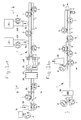
- a conveyor 1 comprises an endless chain 2 of driveable stainless steel links 3 (fig. 8), entrained around a vertically disposed drive sprocket at one end and an idler sprocket at the other end.
- Drive means includes a motor 5 and gearbox 6 (fig. 1b). Sprockets, switchgear an controls are conventional and are not illustrated.
- Each second or alternate link 3 is integral with a respective rectangular stainless steel plate 4.
- the plates line up, in the upper section of the conveyor in use, to yield the endless chain 2 in the form of a substantially unbroken moving platform.
- the table 7 and the convevor 1 are mounted on a floor-supported framework (not illustrated) which is conventional, and which also supports the various automatic tools.
- Each pair of adjacent plates 4 bears pig's head supporting means which comprise a chair 8 welded to one member of the pair and a pair of locating rods 9 swivelably mounted on an upstanding pillar 10 welded to the other member.
- the rods 9 having one rest position pointing upstream and another pointing downstream of the conveying direction, so that a pigs' head positioned thereon can be inverted by pivoting to face in either direction.
- the conveyor 1 is provided with automatic tools mounted on its framework and disposed as follows in the conveying direction: a pigs' head inverter 20, a washing unit 30, an incising and deboning tool group 40, and a bonecutting circular saw 80, all of which are described in more detail below.
- Ancillary equipment includes a circular saw 91 for snout removal, two de-rinding machine 92, 93 with respective feed tables 94, 95,
- a second, recovery conveyor located below level and conveying in the opposite direction to the conveyor 1. This second conveyor is not illustrated. Feed chutes, likewise not illustrated, are provided wherever necessary for feeding the recovered meat from the first to the second conveyor.
- manual workers A - T are engaged at the workbench 7 to carry out intermediate process steps for which automatic tools have not, or not yet, been devised.
- the workpieces on which the process operated are pigs' heads 11 from which the snouts have been removed for a length of 5-10 cm by such means as the circular saw 91.
- a safety cable 12 (figs. 3 and 5) freely supported in loops 13 on rods 14 depending from a ceiling or other overhead support above the workbench 7, extends at approximately the eye level of the workers for the entire length of the conveyor 1 and is connected to a microswitch (not shown) to shut down the conveyor on being pulled or pushed.
- the washing and scrubbing unit 30 comprises three powered cylindrical rotary brushes, the spindles of which are movable normally to their respective axes and are elastically biased towards the locus of advance of the pigs' heads 11.
- the brushes comprise two vertically disposed rotary brushes 15 and one horizontal rotary brush 16.
- the unit 30 also comprises means (not shown) for directing several jets of rinsing water at each advancing pig's head 11.
- a high pressure water cleaning unit is used instead of the unit 30 shown in figs. 2 and 3.
- the incising and deboning tool group 40 (Figs 2, 3 and 4) comprises a box framework 41 and, pivotally mounted therein, an incisor 42, a brow scraper 43, a pair of cheek scrapers 44 and a pair of jaw scrapers 45, operable respectively by fluid pressure-driven cylinders 46, 47, 48 and 49.
- the pressure fluid leads which are represented in Fig 4 only by a specimen pair 50 shown in broken outline, are fed ( Fig 1a) by a motor and compressor 51 from a fluid reservoir 52.
- These operating and control elements 51-54 are housed on the top of the framework 41, shown in Fig 1a, and have been omitted from Fig 4.
- the incisor 42 is mounted on a horizontal spindle 55 journalled in the framework 41, and comprises a plate mounting 56 having a downwardly directed incisor blade 57 detachably secured to its underside.
- the blade 57 extends in the vertical plane that contains the conveyor mid-axis.
- the brow scraper 43 is likewise mounted on a horizontal spindle 58 journalled in the framework 41, and comprises a plate mounting 59 having a pair of downwardly directed brow scraper blades 60 detachably secured to its forward edge, perpendicular to the vertical plane that contains the conveyor mid-axis, and with the members of the pair disposed symmetrically about said axis.
- the incisor 42 and the brow scraper 43 are arranged to pivot about respective horizontal axes, those of the respective spindles 55 and 58, under the action of the respective fluid pressure-driven cylinders 46 and 47.
- the cheek scrapers 48 and jaw scrapers 49 are journalled in the framework 41 by means of vertical pivot pairs 61, 62, and carry respective pairs of scraper blades 63, 64 angled towards the aforementioned vertical plane that contains the conveyor mid-axis.
- the deboning tools 42, 43, 44, 45 are pivotally secured to their respective fluid pressure-driven cylinders by respective pins 65, 66 and pin pairs 67, 68, and the cylinders are themselves pivotally mounted on the framework 41 in a similar manner.
- the applied fluid pressure in each cylinder in use is substantially constant, but their arranqement imparts a resilience to the tools 42, 43, 44, 45 in action against an advancing pig's head, to compensate for alterations in the cross-sectional profile of the bony structure of the skull in contact with each said tool as the pig's head advances past the tools.
- the pig's head inverter 20 comprises a downwardly inclined rod 21 rigidly mounted in a sturdy framework 22 secured to the conveyor framework.
- the rod points down at the mid-axis of the conveyor, and its lower end portion 23 is located so as to intercept medially the rear aspect of the front curved portion of the lower mandible of a pig's head 11a presented upside down and moving backwards.
- the encounter results in the head 11a somersaulting about the pivotal mounting of the associated locating rods 9, and passing through the orientations shown in Fig 6 a , b and c to end in the attitude of the head 11b in Fig 5.
- the head 11b in contrast to 11a, is erect and facing forward in the conveying direction.
- the bonecutting tircular saw 80 from which the jaw guard has been removed in the drawing, is stationary and mounted on a frame 81 secured to the conveyor framework, and comprises a drive motor 82 and a saw blade 83.
- the height above the conveyor track 2 of the lower limb of the blade 83 is such as to cut the lower mandible into left and right halves 11d, 11e in an advancing pig's head 11c inverted and facing upstream of the conveyor as shown.
- the chair 8 comprises an upright back member 8c having two prongs 8d directed downstream of the conveyor to enhance the clamping action exerted by said back member 8c on the pig's head against the resistance of the locating rods 9.
- Operator A removes a pig's head from a supply crate (not shown) presents it to the circular saw 91 and removes about 7 cm length of the snout, which is collected in an underneath vessel for later treatment. He then places the desnouted pig's head on the chute 98.
- Operator B places desnouted heads 11 from chute 98 onto the downstream end of the conveyor 1 in the clamp formed by the extensions 8, 9 or two adjacent links 3 of the conveyor chain 2, while they pass around the terminal sprocket. The head is disposed upside down and faces downstream of the conveyor (ie in the conveying direction, see the position of head 11a in fig. 5).
- Operator C also removes the tongue (if still present: heads are sometimes supplied with the tongue removed).
- the advancing head then intercepts the inverter 20, and adopts the upright, forward-facing position of head 11b in fig. 5 as a result, pivoting as shown by the arrow X.
- the head then passes through the high pressure water cleaning unit or the washing and scrubbing unit 30, parting the resiliently mounted brushes 15 and raising brush 16 sufficiently to proceed, while being thoroughly rinsed and brushed, and advances to enter the tool group 40.
- the incisor blade 57 (fig. 3 ), actuated by a sensor and mircoswitch (not shown) in response to the presence of the head, descends to incise the flesh down to the bone along a median dorsal line 102 from the snout stump to behing the ears, in preparation for the separation of the flesh into two discrete masks, left and right.
- the brow scraper 43 similarly actuated, descends to intercept the snout meat and scrape it back towards the brows, in right and left strips.
- the cheek scrapers 44 similarly actuated, close laterally upon the snout stump and drag the flesh back, supported a short time later by similar action on the part of the jaw scrapers 45.
- the head emerges from the tool group 40 with the right and left masks clearly separated from the skull from the snout stump back to the ears, where the masks remain attached.
- the head is then manually re-inverted by pivoting in the direction shown by the arrow Y, to assume once again the attitude shown at 11a in fig. 5.
- the head now advances to the bonecutting saw 80, which divides the lower jawbone into right and left halves as previously described.
- the stripped skull residue is discarded automatically under gravity into chute 97 at the end of the conveyor run. From there it empties to the aforesaid bone and waste conveyor which is not illustrated.
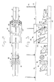
- a swine head 100 is preprocessed by sawing off the snout 101, incising the dorsal midline 102 from snout stump to crown, to the depth of the soft tissue, circumcising the eye 103 with a hand-held power-driven rotary tubular knife, down to the bone, cutting below the lower jaw around the line 104, stripping the right and left masks back from the snout stump to behind the ear 105, and removing the stripped masks with a knife.
- the chain conveyor 106 is powered for forwarding in the direction of the arrow C in fig. 2, to the conventional rotary de-rinding machine 92 via a narrow- transition table 107.
- Two sets, each consisting of a conveyor 106, 106′ and a de-rinder 92, 93 are used, one set for forwarding the left mask (in two pieces) to the de-rinder and de-rinding it, and the other set for forwarding and de-rinding the right mask similarly.
- each convey-or 106 To one side of each convey-or 106 is located a separate cutting table (not illustrated) equipped with a stationary, rigid splitting knife having its blade upstanding from the table surface.
- a respective operator F, H attends each said table, to which the right and left masks respectively are fed following their separation from the head, and prior to their delivery to one of the conveyors 106, 106′.
- the operator grasps the left mask applies it to the splitting knife (whose cutting edge faces away from hin) and draws it past the knife to bisect it along the line 108 thus producing upper and lower left semi-masks U and L respectively.
- the semi-masks are then placed on the conveyor as shown in fig. 10. It will be seer that the ring 109 is lowermost, the meat 110 being out of contact with the conveyor.
- the meat 110 is of adequate de-rinder feeding thickness across the leading edge of each semi-mask in the position used and illustrated.
- the conveyor chain comprises a succession of laterally located, upstanding tractor pins 111 spaced apart along each of its two long edges.
- the upper semi-mask U is now located on a tractor pin 111 with said pin occupying the perforation 112 (in the meat) that represents the former position of the eye.
- An ear knife 113 is mounted with its cutting edge facing out between steel guide rods 114, 115 mounted beside the conveyor 106.
- a supplementary guide rod 116 is disposed with its tip directed at the tip of the guide rod 114 and its shank sloping gently upward and outward from the conveying direction indicated by the arrow C.
- the combined action of the guide rods ensures that the upper semi-mask U to which one ear 105 remains attached has the attachment region thereof presented to the ear knife 113.
- the tractor pin 111 moving with the conveyor 106 is effective to draw the semi-mask U past the ear knife 113 and to sever the ear 105, which drops into a first ear collecting tube (not shown) standing on the floor.
- a second ear collecting tub stands similarly beside and below the second conveyor 106′, and collects the successively severed ears from the (right) masks in this continuous process.
- the blade of the ear knife 113 is provided with an adjusting screw 117 and lock screws 118, 119, all engaged in threaded bores in the guide rods 114, 115.
- a curved stationary steel wire 120 overlaps the conveyor edge and is shaped into a cam for disengagement of the upper semi-mask U from the tractor pins 111 in succession.
- Each upper semi-mask U thus proceeds unencumbered to its destination between the rollers of the de-rinder 92, 93.
- the transition table 107 is shorter than the width of the conveyor by a distance (at each of its ends) sufficient to permit free revolution of the tractor pins 111 despite their projection above the conveying surface of the conveyor 106.
- the conveying surface conveniently comprises plastics strips 121, each of which extends in length to the full width of the conveyor 106 and is articulated to adjacent strips 121 in the manner of a piano hinge, the exposed or bearing surface of each strip 121 bearing a plurality of parallel ribs 121′ which extend in the conveying direction.
- a conveyor 106 cooperates with a de-rinding machine 92, has upstanding lateral tractor pins 111, an ear knife 113, guide members 114, 115 and a supplementary guide member 116.
- the de-rinder 92 comprises a transition table 107, an upper roller 122, a lower roller 123, a de-rinding blade 124, a meat delivery guide plate 125 and a rind delivery guide plate 126.
- the associated arrows show the working directions of rotation of the rollers, including the conveyor rollers.
- the embodiment of figs. 12 and 13 differs from that of figs. 10 and 11 in having a curved-nose ear guiding plate 127 for guiding and constraining the swine ears into the gap between guide rods 115 and 114/116, so as to present them in a uniform manner to the ear knife 113.
- the swine head masks M are placed on the conveyor 106, each located on a respective tractor pin 113, in the attitude or disposition shown in full outline in fig. 12.
- apparatus for deboning discrete, severed swine snouts comprises an endless chain conveyor 130 comprising links 131 entrained around terminal sprockets 132 one of which is driven by a power source which is not illustrated.
- Swine snout receptacles 133 of stainless steel are firmly secured to respective links 131.
- Each receptacle 133 is of a rectangular U-shaped cross-section, the dimensions of which are greater at the forward end 134 and reduced at the rear end 135, the transition between the two cross-sections being marked by a step with a forwardly-directed edge 136.
- the edge 136 follows the three limbs of the rectangular U-shaped cross-section.
- a sturdy framework 137 straddles the conveyor 130 and comprises a bridge 138 from which a barrier block 139 depends centrally.
- the block 139 although disposed directly in the path of the advancing receptacles 133, offers no obstruction to their passage, and in fact is a fairly close fit in the portion 135 of reduced cross-section of each of the receptacles 133.
- the barrier block 139 is also of stainless steel.
- the described apparatus is intended for use in a method of deboning a succession of discrete, severed swine snouts 140, each of which has an anterior surface a, and enclosed plug of bone b, a cut surface c, a dorsal surface d, two lateral surfaces e and a ventral surface v.
- a respective snout 140 is manually fed into each receptacle 133 at a feed end F of the conveyor 130, being inserted into the larger cross-sectional end opening of the receptacle in a direction opposite to the conveying direction.
- each snout 140 comes, in its turn, into contact with the barrier block 139 which then retains and immobilizes the bone plug b while the receptacle 133 continues in its path.
- the step 136 with its sharp edges ensure that the snout 140 is retained in its position, and contributes to the rupture of the rind which converts the dorsal meat d into a flap.
- the flap opens, allowing the bone plug b to escape while the remaining meat of the snout 140 continues towards the discharge end of the conveyor.
- the bone plug b falls downward onto a deflector (not shown) which guides it into a collecting vessel.
- the snout meat is removed in turn from each of the receptacles 133 manually at present, but automatic means for doing this is in course of development.
- the meat is accumulated on a tray to one side of the conveyor.
- the leaded trays are periodically removed for further processing of the meat, and replaced with fresh trays.
- This deboning method according to the invention is many times faster and substantially more efficient than previous methods, all of which were purely manual.
Landscapes
- Life Sciences & Earth Sciences (AREA)
- Engineering & Computer Science (AREA)
- Food Science & Technology (AREA)
- Wood Science & Technology (AREA)
- Zoology (AREA)
- Processing Of Meat And Fish (AREA)
- Meat, Egg Or Seafood Products (AREA)
- Enzymes And Modification Thereof (AREA)
- Medicines Containing Material From Animals Or Micro-Organisms (AREA)
- Medicines That Contain Protein Lipid Enzymes And Other Medicines (AREA)
- Packages (AREA)
- Processing Of Solid Wastes (AREA)
Claims (16)
Priority Applications (1)
| Application Number | Priority Date | Filing Date | Title |
|---|---|---|---|
| AT88903408T ATE77207T1 (de) | 1987-03-24 | 1988-03-22 | Verfahren und vorrichtung zum ausbeinen von fleischstuecken, insbesondere von abgetrennten tierkoepfen. |
Applications Claiming Priority (2)
| Application Number | Priority Date | Filing Date | Title |
|---|---|---|---|
| IE7568787 | 1987-03-24 | ||
| IE75687A IE59198B1 (en) | 1987-03-24 | 1987-03-24 | Improvements in meat recovery from carcase sections |
Publications (2)
| Publication Number | Publication Date |
|---|---|
| EP0309539A1 EP0309539A1 (de) | 1989-04-05 |
| EP0309539B1 true EP0309539B1 (de) | 1992-06-17 |
Family
ID=11017752
Family Applications (1)
| Application Number | Title | Priority Date | Filing Date |
|---|---|---|---|
| EP88903408A Expired - Lifetime EP0309539B1 (de) | 1987-03-24 | 1988-03-22 | Verfahren und vorrichtung zum ausbeinen von fleischstücken, insbesondere von abgetrennten tierköpfen |
Country Status (17)
| Country | Link |
|---|---|
| US (1) | US4918788A (de) |
| EP (1) | EP0309539B1 (de) |
| JP (1) | JP2898002B2 (de) |
| CN (1) | CN1031013A (de) |
| AT (1) | ATE77207T1 (de) |
| AU (1) | AU609473B2 (de) |
| CA (1) | CA1304204C (de) |
| DD (1) | DD298476A5 (de) |
| DE (1) | DE3872134T2 (de) |
| DK (1) | DK648588A (de) |
| FI (1) | FI885437A0 (de) |
| HU (1) | HU206444B (de) |
| IE (1) | IE59198B1 (de) |
| NZ (1) | NZ223982A (de) |
| RU (1) | RU1780499C (de) |
| WO (1) | WO1988007329A2 (de) |
| ZA (1) | ZA88312B (de) |
Cited By (1)
| Publication number | Priority date | Publication date | Assignee | Title |
|---|---|---|---|---|
| WO1998047381A2 (de) | 1997-04-21 | 1998-10-29 | K & S Ingenieurgesellschaft Sondermaschinenbau Gbr Hermann Kischke Und Hermann Schrader | Haltevorrichtungen für fleischteile, ihre anordnung in einer zentrifuge und verfahren zum entbeinen von fleischteilen |
Families Citing this family (36)
| Publication number | Priority date | Publication date | Assignee | Title |
|---|---|---|---|---|
| EP0498818A4 (en) * | 1989-11-03 | 1993-03-31 | Commonwealth Scientific And Industrial Research Organization | Head washing apparatus |
| AU637157B2 (en) * | 1989-11-03 | 1993-05-20 | Australian Meat & Livestock Research & Development Corporation | Head washing apparatus |
| US4998323A (en) * | 1990-01-30 | 1991-03-12 | Foodcraft Equipment Co. | Poultry breast and back skinner |
| NL9001382A (nl) * | 1990-06-18 | 1992-01-16 | Bauke Toren | Werkwijze en inrichting voor het uitbenen van een kop van een geslacht stuk vee. |
| DE4134621C1 (de) * | 1991-10-19 | 1992-10-29 | Nordischer Maschinenbau Rud. Baader Gmbh + Co Kg, 2400 Luebeck, De | |
| NL9200733A (nl) * | 1992-04-22 | 1993-11-16 | Passchier Bob | Inrichting en werkwijzen voor het losnemen en/of verwijderen van vlees en dergelijke van dierkoppen. |
| NL9201426A (nl) * | 1992-04-23 | 1993-11-16 | Stork Protecon Bv | Werkwijze en inrichting voor het voor machinale ontbening voorbereiden van een varkenskop. |
| NZ243718A (en) * | 1992-07-24 | 1995-09-26 | New Zealand Meat Ind Res Inst | Removing cheek meat from head of animal carcass |
| US5533928A (en) * | 1995-02-27 | 1996-07-09 | Kentmaster Mfg. Co., Inc. | Animal head processing apparatus |
| AU698532B2 (en) * | 1995-08-04 | 1998-10-29 | Commonwealth Scientific And Industrial Research Organisation | Head meat recovery |
| AUPN461995A0 (en) * | 1995-08-04 | 1995-08-31 | Commonwealth Scientific And Industrial Research Organisation | Head meat recovery |
| US5584757A (en) * | 1996-07-03 | 1996-12-17 | Kentmaster Mfg. Co., Inc. | Animal head processing apparatus with hog snout puller |
| DK200000459A (da) | 2000-03-20 | 2001-09-21 | Slagteriernes Forskningsinst | Udstyr og fremgangsmåde til automatisk udstikning af kæbesnitten på en slagtekrop |
| DE60212067T2 (de) | 2001-01-16 | 2006-11-30 | Scanvaegt International A/S | Zuschneidetisch |
| WO2004068953A1 (ja) * | 2003-02-03 | 2004-08-19 | Mayekawa Mfg.Co., Ltd. | 食肉脱骨装置 |
| CA2578740A1 (en) * | 2004-09-01 | 2006-03-09 | Cargill, Incorporated | Head meat system |
| US8231443B1 (en) * | 2011-02-11 | 2012-07-31 | Tyson Foods, Inc. | Method and apparatus for processing a neck bone |
| AU2007222899B2 (en) * | 2006-03-09 | 2013-05-23 | Nordischer Maschinenbau Rud. Baader Gmbh + Co. Kg | Processing fish including rotation thereof |
| WO2010114397A1 (en) * | 2009-04-03 | 2010-10-07 | Robotic Technologies Limited | Carcass cutting methods and apparatus |
| DK3508064T3 (da) * | 2009-12-17 | 2021-02-01 | Marel Meat Bv | System and method for processing slaughtered animals and/or parts thereof |
| CN101912121B (zh) * | 2010-08-17 | 2011-07-27 | 庆云瑞丰食品有限公司 | 烤鸭剔骨新工艺 |
| CN102113536B (zh) * | 2010-12-06 | 2012-07-11 | 湖南颐丰食品有限公司 | 冰鲜分割猪肉的加工方法 |
| CN103264879B (zh) * | 2013-05-01 | 2015-07-08 | 句容市红掌食品有限公司 | 一种肉加工自动化流水线系统 |
| CN107912513A (zh) * | 2017-11-16 | 2018-04-17 | 正大食品(襄阳)有限公司 | 分割猪头操作台 |
| CN107821560A (zh) * | 2017-12-14 | 2018-03-23 | 安徽省福润肉类加工有限公司 | 一种猪肉处理台 |
| KR102466088B1 (ko) * | 2020-04-20 | 2022-11-10 | 장주영 | 가공식품 배가름 절단장치 |
| KR102482884B1 (ko) * | 2020-07-16 | 2022-12-29 | 주식회사 디에프에스 | 목뼈 자동손질장치 |
| CN111771944B (zh) * | 2020-07-30 | 2021-11-02 | 长宁县九牛食品有限责任公司 | 一种肉牛屠宰线 |
| CN112155043B (zh) * | 2020-08-26 | 2021-12-24 | 宁波大学 | 一种一体式绞肉机 |
| CN115915946B (zh) * | 2020-08-31 | 2025-02-25 | 马瑞奥肉品私人有限公司 | 用于四足屠宰动物的屠体腿部部分的去骨的方法和系统,用于从屠体腿部部分的骨头移除肉 |
| CN112106940A (zh) * | 2020-09-30 | 2020-12-22 | 重庆市合川区麒麟畜产品有限责任公司 | 猪头生产系统 |
| CN113001796B (zh) * | 2021-02-20 | 2023-04-25 | 新余学院 | 一种多晶硅锭杂质层截除装置 |
| CN112923062B (zh) | 2021-03-29 | 2021-10-26 | 清华大学 | 用于密封液体介质的磁性液体密封装置 |
| CN114176104B (zh) * | 2021-11-23 | 2023-07-14 | 北京机械工业自动化研究所有限公司 | 一种畜类胴体剔骨分割装置和方法 |
| CN116172037A (zh) * | 2023-04-11 | 2023-05-30 | 广东民昇食品有限公司 | 一种生猪屠宰系统 |
| CN121049242A (zh) * | 2023-12-06 | 2025-12-02 | 青海大学 | 一种牦牛头部位肉的品质评价方法 |
Family Cites Families (14)
| Publication number | Priority date | Publication date | Assignee | Title |
|---|---|---|---|---|
| FR992684A (fr) * | 1944-08-03 | 1951-10-22 | Renondin | Dispositif de manutention pouvant saisir, transporter, maintenir, libérer et éventuellement ranger des objets uniformes |
| US2953240A (en) * | 1956-05-09 | 1960-09-20 | Ralph W Johns | Package conveyor |
| FR2260954B1 (de) * | 1974-02-15 | 1978-01-06 | Thillet Antoine | |
| US3982299A (en) * | 1975-05-01 | 1976-09-28 | Burns Foods Limited | Meat cutter |
| US4041572A (en) * | 1976-09-27 | 1977-08-16 | Victor F. Weaver, Inc. | Anatomical section de-boning machine |
| DE2726918C2 (de) * | 1977-06-15 | 1986-09-04 | K.J. Maskinfabriken A/S, Hjerting | Vorrichtung zum Abtrennen der Speckschicht von Kotelett-Strängen |
| FR2441340A1 (fr) * | 1978-11-15 | 1980-06-13 | Blache Et Cie Parmentiere P | Appareil pour immobiliser la tete d'un animal de boucherie separee du corps |
| US4237580A (en) * | 1979-06-28 | 1980-12-09 | Croasdell Desmond Francis | Half pig's head boning method and apparatus |
| US4385419A (en) * | 1982-03-15 | 1983-05-31 | Cantrell Machine Co., Inc. | Chicken deboning apparatus and method |
| US4495675A (en) * | 1982-04-12 | 1985-01-29 | Hill Carl J | Method and apparatus for removing meat from the knuckled end of a bone |
| US4543689A (en) * | 1983-08-01 | 1985-10-01 | Ibp, Inc. | Method and apparatus for removing cheek meat from the skulls of slaughtered animals |
| EP0188421A4 (de) * | 1983-09-09 | 1986-09-15 | Halse Norman James | Verbesserte mittel zum öffnen von kadavern. |
| US4644608A (en) * | 1984-01-16 | 1987-02-24 | Foodcraft Equipment Company, Inc. | Thigh deboner |
| FR2581512B1 (fr) * | 1985-05-13 | 1987-07-31 | Cotentin Viandes | Installation de desossage de quartiers arriere de bovins |
-
1987
- 1987-03-24 IE IE75687A patent/IE59198B1/en not_active IP Right Cessation
-
1988
- 1988-01-18 ZA ZA880312A patent/ZA88312B/xx unknown
- 1988-03-22 US US07/297,260 patent/US4918788A/en not_active Expired - Fee Related
- 1988-03-22 AT AT88903408T patent/ATE77207T1/de not_active IP Right Cessation
- 1988-03-22 EP EP88903408A patent/EP0309539B1/de not_active Expired - Lifetime
- 1988-03-22 AU AU15713/88A patent/AU609473B2/en not_active Ceased
- 1988-03-22 WO PCT/NL1988/000011 patent/WO1988007329A2/en not_active Ceased
- 1988-03-22 DE DE8888903408T patent/DE3872134T2/de not_active Expired - Fee Related
- 1988-03-22 JP JP63503100A patent/JP2898002B2/ja not_active Expired - Lifetime
- 1988-03-22 HU HU882547A patent/HU206444B/hu not_active IP Right Cessation
- 1988-03-23 CA CA000562258A patent/CA1304204C/en not_active Expired - Lifetime
- 1988-03-23 NZ NZ223982A patent/NZ223982A/en unknown
- 1988-03-23 DD DD88313926A patent/DD298476A5/de not_active IP Right Cessation
- 1988-03-24 CN CN88102727A patent/CN1031013A/zh active Pending
- 1988-11-21 DK DK648588A patent/DK648588A/da not_active Application Discontinuation
- 1988-11-23 FI FI885437A patent/FI885437A0/fi not_active IP Right Cessation
- 1988-11-23 RU SU884613171A patent/RU1780499C/ru active
Cited By (1)
| Publication number | Priority date | Publication date | Assignee | Title |
|---|---|---|---|---|
| WO1998047381A2 (de) | 1997-04-21 | 1998-10-29 | K & S Ingenieurgesellschaft Sondermaschinenbau Gbr Hermann Kischke Und Hermann Schrader | Haltevorrichtungen für fleischteile, ihre anordnung in einer zentrifuge und verfahren zum entbeinen von fleischteilen |
Also Published As
| Publication number | Publication date |
|---|---|
| IE870756L (en) | 1988-09-24 |
| AU1571388A (en) | 1988-11-02 |
| JPH01502796A (ja) | 1989-09-28 |
| HUT50001A (en) | 1989-12-28 |
| JP2898002B2 (ja) | 1999-05-31 |
| US4918788A (en) | 1990-04-24 |
| RU1780499C (ru) | 1992-12-07 |
| CA1304204C (en) | 1992-06-30 |
| FI885437A7 (fi) | 1988-11-23 |
| EP0309539A1 (de) | 1989-04-05 |
| WO1988007329A2 (en) | 1988-10-06 |
| IE59198B1 (en) | 1994-05-18 |
| CN1031013A (zh) | 1989-02-15 |
| WO1988007329A3 (en) | 1988-11-17 |
| DK648588A (da) | 1989-01-19 |
| FI885437A0 (fi) | 1988-11-23 |
| HU206444B (en) | 1992-11-30 |
| DE3872134T2 (de) | 1993-03-04 |
| DD298476A5 (de) | 1992-02-27 |
| ATE77207T1 (de) | 1992-07-15 |
| DK648588D0 (da) | 1988-11-21 |
| AU609473B2 (en) | 1991-05-02 |
| DE3872134D1 (de) | 1992-07-23 |
| ZA88312B (en) | 1988-07-04 |
| NZ223982A (en) | 1990-04-26 |
Similar Documents
| Publication | Publication Date | Title |
|---|---|---|
| EP0309539B1 (de) | Verfahren und vorrichtung zum ausbeinen von fleischstücken, insbesondere von abgetrennten tierköpfen | |
| US5188559A (en) | Method and apparatus for separating the legs from the back of a poultry carcass | |
| US6322438B1 (en) | Poultry leg and thigh processor | |
| CA2418338C (en) | Dual blade loin knife assembly for automatic loin puller apparatus | |
| CA1326335C (en) | Automatic animal processing | |
| US3348261A (en) | Method for removing meat from poultry legs | |
| BRPI1002728A2 (pt) | esfolador de ombro e de pescoço de aves domésticas | |
| JPH07506480A (ja) | 脚肉剥し器を備えた黒身肉用骨除去器 | |
| US5954574A (en) | Wing remover | |
| US5512013A (en) | Device for detaching and/or removing meat and the like from animal heads | |
| DE69802862T2 (de) | Verfahren und Vorrichtung zum Ausweiden von Schlachttierkörpern | |
| US4297764A (en) | Method and installation for processing bovine feet | |
| US3992734A (en) | Boning meat | |
| US3216056A (en) | Apparatus for removing meat from poultry legs | |
| US3837045A (en) | Process and apparatus for eviscerating poultry | |
| EP1190625B1 (de) | Verfahren und Vorrichtung zum Filetieren von Fischen | |
| JPH10150912A (ja) | 屠体処理装置のレッグプロセッサー | |
| EP0784932B1 (de) | Flügel-Entferner | |
| CA1327434C (en) | Automatic animal processing | |
| WO2005053412A1 (en) | Method and device for detaching a bone part from a carcass part | |
| EP1236401A1 (de) | Einrichtung und Verfahren zum Entfernen der Wirbelsäule aus Schlachttierkörpern | |
| EP0509613A2 (de) | Vorrichtung zur automatischen Schneiden von Tierbrüsten | |
| JPH0793863B2 (ja) | バックプラー | |
| AU2014227479A1 (en) | An Improved Tool for Removing the Pelt or Hide From an Animal Carcass | |
| NZ235513A (en) | Apparatus for cutting brisket of animal carcass |
Legal Events
| Date | Code | Title | Description |
|---|---|---|---|
| PUAI | Public reference made under article 153(3) epc to a published international application that has entered the european phase |
Free format text: ORIGINAL CODE: 0009012 |
|
| 17P | Request for examination filed |
Effective date: 19881114 |
|
| AK | Designated contracting states |
Kind code of ref document: A1 Designated state(s): AT BE CH DE FR GB IT LI LU NL SE |
|
| 17Q | First examination report despatched |
Effective date: 19900612 |
|
| GRAA | (expected) grant |
Free format text: ORIGINAL CODE: 0009210 |
|
| AK | Designated contracting states |
Kind code of ref document: B1 Designated state(s): AT BE CH DE FR GB IT LI LU NL SE |
|
| REF | Corresponds to: |
Ref document number: 77207 Country of ref document: AT Date of ref document: 19920715 Kind code of ref document: T |
|
| ITF | It: translation for a ep patent filed | ||
| REF | Corresponds to: |
Ref document number: 3872134 Country of ref document: DE Date of ref document: 19920723 |
|
| ET | Fr: translation filed | ||
| PLBE | No opposition filed within time limit |
Free format text: ORIGINAL CODE: 0009261 |
|
| STAA | Information on the status of an ep patent application or granted ep patent |
Free format text: STATUS: NO OPPOSITION FILED WITHIN TIME LIMIT |
|
| 26N | No opposition filed | ||
| EPTA | Lu: last paid annual fee | ||
| EAL | Se: european patent in force in sweden |
Ref document number: 88903408.8 |
|
| PGFP | Annual fee paid to national office [announced via postgrant information from national office to epo] |
Ref country code: AT Payment date: 19960313 Year of fee payment: 9 |
|
| PGFP | Annual fee paid to national office [announced via postgrant information from national office to epo] |
Ref country code: SE Payment date: 19960315 Year of fee payment: 9 |
|
| PGFP | Annual fee paid to national office [announced via postgrant information from national office to epo] |
Ref country code: LU Payment date: 19960401 Year of fee payment: 9 |
|
| PGFP | Annual fee paid to national office [announced via postgrant information from national office to epo] |
Ref country code: CH Payment date: 19960412 Year of fee payment: 9 |
|
| PG25 | Lapsed in a contracting state [announced via postgrant information from national office to epo] |
Ref country code: LU Free format text: LAPSE BECAUSE OF NON-PAYMENT OF DUE FEES Effective date: 19970322 Ref country code: AT Effective date: 19970322 |
|
| PG25 | Lapsed in a contracting state [announced via postgrant information from national office to epo] |
Ref country code: SE Effective date: 19970323 |
|
| PG25 | Lapsed in a contracting state [announced via postgrant information from national office to epo] |
Ref country code: LI Effective date: 19970331 Ref country code: CH Effective date: 19970331 |
|
| REG | Reference to a national code |
Ref country code: CH Ref legal event code: PL |
|
| EUG | Se: european patent has lapsed |
Ref document number: 88903408.8 |
|
| NLS | Nl: assignments of ep-patents |
Owner name: STORK MPS B.V.;STORK R.M.S. B.V. |
|
| REG | Reference to a national code |
Ref country code: GB Ref legal event code: 732E |
|
| REG | Reference to a national code |
Ref country code: FR Ref legal event code: TP |
|
| BECA | Be: change of holder's address |
Free format text: 980716 *STORK MPS B.V.:ALBERT SCHWEITZERSTRAAT33, 7131 LICHTENVOORDE |
|
| BECH | Be: change of holder |
Free format text: 980716 *STORK MPS B.V.:ALBERT SCHWEITZERSTRAAT33, 7131 LICHTENVOORDE |
|
| PGFP | Annual fee paid to national office [announced via postgrant information from national office to epo] |
Ref country code: FR Payment date: 19990309 Year of fee payment: 12 |
|
| PGFP | Annual fee paid to national office [announced via postgrant information from national office to epo] |
Ref country code: GB Payment date: 19990325 Year of fee payment: 12 |
|
| PGFP | Annual fee paid to national office [announced via postgrant information from national office to epo] |
Ref country code: DE Payment date: 19990326 Year of fee payment: 12 |
|
| PGFP | Annual fee paid to national office [announced via postgrant information from national office to epo] |
Ref country code: NL Payment date: 19990331 Year of fee payment: 12 |
|
| PGFP | Annual fee paid to national office [announced via postgrant information from national office to epo] |
Ref country code: BE Payment date: 19990517 Year of fee payment: 12 |
|
| PG25 | Lapsed in a contracting state [announced via postgrant information from national office to epo] |
Ref country code: GB Free format text: LAPSE BECAUSE OF NON-PAYMENT OF DUE FEES Effective date: 20000322 |
|
| PG25 | Lapsed in a contracting state [announced via postgrant information from national office to epo] |
Ref country code: BE Free format text: LAPSE BECAUSE OF NON-PAYMENT OF DUE FEES Effective date: 20000331 |
|
| BERE | Be: lapsed |
Owner name: STORK MPS B.V. Effective date: 20000331 |
|
| PG25 | Lapsed in a contracting state [announced via postgrant information from national office to epo] |
Ref country code: NL Free format text: LAPSE BECAUSE OF NON-PAYMENT OF DUE FEES Effective date: 20001001 |
|
| GBPC | Gb: european patent ceased through non-payment of renewal fee |
Effective date: 20000322 |
|
| PG25 | Lapsed in a contracting state [announced via postgrant information from national office to epo] |
Ref country code: FR Free format text: LAPSE BECAUSE OF NON-PAYMENT OF DUE FEES Effective date: 20001130 |
|
| NLV4 | Nl: lapsed or anulled due to non-payment of the annual fee |
Effective date: 20001001 |
|
| REG | Reference to a national code |
Ref country code: FR Ref legal event code: ST |
|
| PG25 | Lapsed in a contracting state [announced via postgrant information from national office to epo] |
Ref country code: DE Free format text: LAPSE BECAUSE OF NON-PAYMENT OF DUE FEES Effective date: 20010103 |
|
| PG25 | Lapsed in a contracting state [announced via postgrant information from national office to epo] |
Ref country code: IT Free format text: LAPSE BECAUSE OF NON-PAYMENT OF DUE FEES;WARNING: LAPSES OF ITALIAN PATENTS WITH EFFECTIVE DATE BEFORE 2007 MAY HAVE OCCURRED AT ANY TIME BEFORE 2007. THE CORRECT EFFECTIVE DATE MAY BE DIFFERENT FROM THE ONE RECORDED. Effective date: 20050322 |