EP0308272A1 - Mehrkammertintenstrahlaufzeichnungskopf für den Farbgebrauch - Google Patents
Mehrkammertintenstrahlaufzeichnungskopf für den Farbgebrauch Download PDFInfo
- Publication number
- EP0308272A1 EP0308272A1 EP88308650A EP88308650A EP0308272A1 EP 0308272 A1 EP0308272 A1 EP 0308272A1 EP 88308650 A EP88308650 A EP 88308650A EP 88308650 A EP88308650 A EP 88308650A EP 0308272 A1 EP0308272 A1 EP 0308272A1
- Authority
- EP
- European Patent Office
- Prior art keywords
- nozzle
- nozzles
- ink
- group
- ink jet
- Prior art date
- Legal status (The legal status is an assumption and is not a legal conclusion. Google has not performed a legal analysis and makes no representation as to the accuracy of the status listed.)
- Granted
Links
Images


Classifications
-
- B—PERFORMING OPERATIONS; TRANSPORTING
- B41—PRINTING; LINING MACHINES; TYPEWRITERS; STAMPS
- B41J—TYPEWRITERS; SELECTIVE PRINTING MECHANISMS, i.e. MECHANISMS PRINTING OTHERWISE THAN FROM A FORME; CORRECTION OF TYPOGRAPHICAL ERRORS
- B41J2/00—Typewriters or selective printing mechanisms characterised by the printing or marking process for which they are designed
- B41J2/005—Typewriters or selective printing mechanisms characterised by the printing or marking process for which they are designed characterised by bringing liquid or particles selectively into contact with a printing material
- B41J2/01—Ink jet
- B41J2/135—Nozzles
- B41J2/14—Structure thereof only for on-demand ink jet heads
- B41J2/14016—Structure of bubble jet print heads
- B41J2/14024—Assembling head parts
-
- B—PERFORMING OPERATIONS; TRANSPORTING
- B41—PRINTING; LINING MACHINES; TYPEWRITERS; STAMPS
- B41J—TYPEWRITERS; SELECTIVE PRINTING MECHANISMS, i.e. MECHANISMS PRINTING OTHERWISE THAN FROM A FORME; CORRECTION OF TYPOGRAPHICAL ERRORS
- B41J2/00—Typewriters or selective printing mechanisms characterised by the printing or marking process for which they are designed
- B41J2/005—Typewriters or selective printing mechanisms characterised by the printing or marking process for which they are designed characterised by bringing liquid or particles selectively into contact with a printing material
- B41J2/01—Ink jet
- B41J2/135—Nozzles
- B41J2/14—Structure thereof only for on-demand ink jet heads
- B41J2/14016—Structure of bubble jet print heads
- B41J2/14088—Structure of heating means
- B41J2/14112—Resistive element
- B41J2/14129—Layer structure
-
- B—PERFORMING OPERATIONS; TRANSPORTING
- B41—PRINTING; LINING MACHINES; TYPEWRITERS; STAMPS
- B41J—TYPEWRITERS; SELECTIVE PRINTING MECHANISMS, i.e. MECHANISMS PRINTING OTHERWISE THAN FROM A FORME; CORRECTION OF TYPOGRAPHICAL ERRORS
- B41J2/00—Typewriters or selective printing mechanisms characterised by the printing or marking process for which they are designed
- B41J2/005—Typewriters or selective printing mechanisms characterised by the printing or marking process for which they are designed characterised by bringing liquid or particles selectively into contact with a printing material
- B41J2/01—Ink jet
- B41J2/135—Nozzles
- B41J2/145—Arrangement thereof
- B41J2/15—Arrangement thereof for serial printing
-
- B—PERFORMING OPERATIONS; TRANSPORTING
- B41—PRINTING; LINING MACHINES; TYPEWRITERS; STAMPS
- B41J—TYPEWRITERS; SELECTIVE PRINTING MECHANISMS, i.e. MECHANISMS PRINTING OTHERWISE THAN FROM A FORME; CORRECTION OF TYPOGRAPHICAL ERRORS
- B41J2/00—Typewriters or selective printing mechanisms characterised by the printing or marking process for which they are designed
- B41J2/005—Typewriters or selective printing mechanisms characterised by the printing or marking process for which they are designed characterised by bringing liquid or particles selectively into contact with a printing material
- B41J2/01—Ink jet
- B41J2/21—Ink jet for multi-colour printing
- B41J2/2132—Print quality control characterised by dot disposition, e.g. for reducing white stripes or banding
Definitions
- This invention relates to multi-chamber ink jet recording heads providing ink isolation and selective access to differing colors of ink in the respective chambers for printing text or graphics. More particularly, this invention is directed to a multichamber ink jet recording head having an improved nozzle plate employing nozzle formats in individual nozzle groups, corresponding to those of a single color recording head with which it is interchangeable.
- Ink jet recording heads are used in printers and plotters. These include thermal and piezoelectric types for expelling ink.
- printer as used herein is used as a term of convenience and is not intended to exclude other types of recording such as plotting.
- Black ink is used in most printing applications, but there is a developing need for the use of colored inks in printing text and graphics.
- printers having recording heads designed for single color printing have not been retrofitted with color recording heads which may be interchangeably fittable in the printer carriage designed for the single color recording head, because of differing requirements resulting from pen body configurations, usually larger for accommodating several colors of ink, nozzle spacing and grouping, and control requirements, to name a few.
- multicolor recording heads can be provided with a chamber for black ink, where a printer is predominately used for black text or graphics, a supply of black ink in a multicolor recording head fitting an all black or other single color recording head carriage mount is limited in volume.
- interchangeable single color/multicolor recording heads in a printer increase the utility of an otherwise single color printer or recorder.
- Patents 4,511,907; 4,540,996; 4,611,219; 4,630,076 and 4,631,548 are related to this invention in the sense that they are all directed to multi-color ink jet printers. None of these, however, appear to teach or to suggest a configuration for a multicolor recording head which is interchangeable with a single color recording head in a single color printer.
- Patent 4,511,907 describes a color printer having a plurality of recording heads arranged in a horizontal direction, the nozzles in each being arranged in a vertical direction.
- the signals for printing are delayed for the second and subsequent recording heads by the time required for the carriage to move the distance between the first recording head and the second or subsequent recording heads.
- Patent 4,540,996 describes the positioning of a plurality of different color recording heads in the scan direction with respect to one another and the nozzles in each in terms of dot intervals for the purpose of defining an arrangement preventing double recording.
- Patent 4,611,219 describes a liquid jetting printer comprising a plurality of perforated plates providing two channel isolation with alternate ink passages for thermal ink jet operation.
- Patent 4,630,076 describes a multicolor recording head having horizontally spaced nozzle groups, each of which includes a row of nozzles inclined at an angle to the horizontal. An arrangement is described employing white or transparent dot over printing of a previously deposited color dot to cause color bleeding for achieving color tinting.
- Patent 4,631,548 provides a plurality of ink reservoirs for different colors of ink in an ink jet printer. Multicolor images are printed using the dot matrix principle. Dot diameter is controlled, either by adjusting the volume of ink in each droplet inversely with a number of droplets in a matrix dot, or preselecting a constant volume for the droplets and using the same number of the same or different colors of droplets in forming each matrix dot.
- a multicolor ink jet pen having a printhead characterized in that said printhead comprises a first group of nozzles and a second group of nozzles positioned in adjacent printing rows on said printhead with the groups in each row being staggered and spatially offset with respect to the groups in an adjacent row, whereby nozzle packing density is maximized while nozzle crosstalk is minimized.
- a multichamber ink jet pen for a recording apparatus, characterized in that it comprises: a pen body having a plurality of ink chambers; a printhead having a plurality of spaced openings therein and a nozzle group at each opening means mounting said printhead on said pen body means providing respective individual passages between said chambers and said openings at said printhead at said nozzle groups, providing an individual ink path between each chamber and a corresponding nozzle group each nozzle group having a center at said openings and comprising at least one column of equally spaced nozzles the center of the group of nozzles being parallel to the center of the group of nozzles, the centers of the groups being laterally spaced apart a predetermined number of dot row spaces; and the end nozzle of each column being spaced at least one dot row space from the adjacent end nozzle in an adjacent nozzle group, measured in a direction parallel to the nozzle columns.
- a multichamber ink jet pen for a recording apparatus which can be fitted either with the multichamber ink jet pen or a single color ink jet pen characterized in that the multichamber ink jet pen comprises a nozzle group of nozzles connected to each chamber, the respective nozzles in each group arranged in a format corresponding to that of the single color ink jet pen.
- nozzle group duplicates a different longitudinal segment of the nozzle column pattern of the single color inkjet pen, the sum of the nozzles in all of the nozzle groups being no greater than the number of nozzles in the nozzle column pattern of the single colour pen, the nozzle groups being alternately disposed in two columns in a non-overlapping, end-to-end sequence, duplicating the longitudinal spacing of the nozzles of the nozzle column pattern of the single colour pen within and between the nozzle groups.
- each nozzle group duplicates a different nozzle column segment of the nozzle column pattern of said single color inkjet pen and comprises of a number of nozzles representing a selected sub-multiple of the total number of nozzles of the single color inkjet pen; the nozzle groups being positioned in end-to-end relationship on said printhead in a pattern maintaining the nozzle column direction the nozzle sequence and the nozzle spacing of the nozzle column pattern of the single color inkjet pen.
- a multi-color inkjet pen having a plurality of nozzle groups disposed in end-to-end relationship, each having predefined length and width dimensions, each nozzle group receiving a different color of ink characterised in that each nozzle group is laterally offset with respect to each adjacent nozzle group by at least a distance greater than said width dimension, whereby a sealing surface area is provided between and around each nozzle group for isolating the respective colors of ink at each nozzle group.
- the configuration of the nozzles within the nozzle groups and the configuration of the nozzle groups are such that uniform spacing within and between the nozzle groups is maintained.
- a multichamber ink jet recording head or pen for color use is provided which is retrofittable to a single color ink jet printer.
- a nozzle layout is provided such that even size paper steps in the paper feed direction allows full color printing with only about a 3% reduction in printable area.
- Color separation is provided by staggering the individual color groups of nozzles in the scan direction while maintaining the same dot per inch spacing of the nozzles within the groups and between the g roups as in the si ngle color printhead.
- Construction of the multicolor ink jet pen is essentially the same as that of the single color pen especially as to size and external configuration and as to the pen mounting details in the pen carriage. Only changes are made in the interior of the ink reservoir to provide for the isolated storing of four colors of ink and to the nozzle substrate to provide the separate color channels for printing.
- a disposable type thermal ink jet recording head or pen is employed in describing this invention.
- the invention is not limited to a thermal ink jet type of pen, but is equally applicable to a piezoelectric type of ink jet pen.
- the printer or plotter in which the recording head or pen is mounted is not shown, it being understood that constant speed relative motion in one direction between the printing medium and the pen provides scanning for printing a line of text or graphics and that stepping relative motion between the printing medium and the pen in a direction orthogonal to the one direction positions the ink jet pen to print the next line of text or graphics.
- the recording head or pen illustrated comprises a printhead 60.
- the printhead comprises an orifice or nozzle plate 60a, containing nozzles 62 arranged in four nozzle groups 62a, 62b, 62c and 62d.
- the nozzle plate 60a is attached to a patterned substrate 61 having a thin film resistor array with an integral ink pathway which is in turn sealed in a cavity or recess 64 in a front plate 66 which is part of a plastic pen body 68 having individual ink chambers 68a, 68b, 68c and 68d which carry the ink supply.
- Each nozzle 62 supplies ink droplets on demand or command from the printer control system as the pen scans the print medium.
- the droplets of ink are ejected by instantaneously vaporizing a tiny volume of ink.
- the vapor bubble grows rapidly displacing and giving momentum to the ink between the bubble and the nozzle, which expels the ink through the selected nozzle onto the print medium.
- Ink is refilled automatically in the nozzle as the vapor bubble collapses.
- Blocks of foam 70a, 70b, 70c and 70d are compressed in the respective chambers of the ink reservoir.
- this foam material may be a reticulated polyurethane foam of the type disclosed in copending European patent application 87305776.4,publication No.0261764, entitled "Thermal Ink Jet Pen Body Construction Having Improved Ink Storage and Feed Capability and Multicolor Ink Dispensing Capability and Low Cost Construction", assigned to the present assignee and incorporated herein by reference.
- These blocks of foam are individually saturated with ink of the selected color, typically black, yellow, cyan and magenta.
- the reservoirs are sealed by a rear cover plate 72 provided with individual vent holes 74 for venting the respective ink chambers to the atmosphere. Provision (not shown) is made for preventing ink leakage out of these ports.
- the pen is mounted with the nozzle plate 60a pointed downwardly.
- Ink is delivered to the nozzle plate under the influence of capillary force supplied by the ink pathway and the nozzles themselves.
- each of the foam filled ink chambers is provided with an opening. These are designated 68e, 68f, 68g and 68h. These are the ink chamber exit ports through which ink is delivered to each of the respective nozzle groups 62a, 62b, 62c, 62d in the printhead 60.
- the individual ink paths for ink delivery from the ink chambers to the respective nozzle groups in the printhead 60 are defined by a sealing plate 76 having respective openings 76a, 76b, 76c and 76d therethrough, which provide the respective isolated channels or ink flow paths between the individual ports 68e-68h and the individual ports 64a, 64b, 64c, 64d, respectively, opening through the front plate 66 into the recess 64 in which the printhead 60 is sealed.
- These ports, e.g. 64a-64d are in the geometry of elongated slots herein, and such slot-feed ink flow techniques and related electrical interconnect methods are known in the art. These techniques and methods are described for example in U.S.
- the pattern of the ports 64a-64d corresponds to the pattern of the nozzle groups 62a-62d in the plate 60.
- the sealing plate 76 is provided with a beaded peripheral edge and beaded edges around each of the openings 76a-76d to provided positive sealing when compressed between the end face of the reservoir of the pen body 68 and the back face of the front plate 66.
- the patterned substrate 61 is provided with electrical contact pads 62e along the side edges of its face which individually communicate through circuit traces with the resistors at the nozzles which fire the drops of ink. These contact pads are schematically seen in Fig. 1.
- One patterned substrate format, detailing the circuit connections with the resistors, is seen in Figure 5, which will be described at a later point.
- These contact pads are individually engaged by corresponding contact points on the back side of a flexible circuit 78 having flexible circuit traces 78a thereon.
- the flexible circuit 78 has an opening through its face which straddles the plate 60. The edges of this opening overlap the contact pads 62e and are indexed with contact pads on the patterned substrate 61 to make electrical connections.
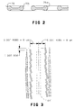
- Figure 3 illustrates a pattern or format of one type of single color nozzle or orifice plate.
- This nozzle plate comprises two columns of nozzles, there being 25 nozzles in each column.
- the nozzles in each column are arranged in staggered groups of 3 as seen.
- the nozzles in the right column which are the odd numbered nozzles, 1-49, are displaced vertically, as viewed, with respect to the nozzles in the left column which are the even numbered nozzles, 2-50, by one-half the distance between the nozzles in the columns.
- the distance between the nozzles in the right column and the left column measured in a direction parallel to the columns, as indicated, is identified as one dot row or logical print position.
- the distance between the nozzle center line and the top nozzle in each row measured horizontally for nozzle number 2 is 5 dot rows minus 8um and for the nozzle number 1 is 5 dot rows plus 8um.
- a dot row or logical print position is .0033 inches and the total distance between corresponding nozzles, such as nozzle 1 and nozzle 2, is typically 10 dot rows and thus 0.033 inches.
- the nozzles are staggered in the columns, typically in groups of three (3).
- Table I illustrates the firing sequence of the resistors associated with each of the nozzles of Fig. 3.
- the timing signal diagram for the nozzle array of Figure 3 is seen in Figure 4, identifying the resistors fired with each pulse.
- the resistors on the recording head must be fired in a particular order to minimize cross talk.
- the location of the orifices is set so that the dots will all be fired in the same vertical column when there is a constant scan or printing velocity, typically 12 in./sec., with a 3.25 usec. electrical pulse width TPW and a 5.75 usec dead time TDT, or interval between pulses.
- the dot firing sequence and relative nozzle locations in microns are specified in Table I. When printing left to right, the indicated sequence is used. When printing right to left, the resistors are fired in the reverse sequence.
- the printhead 60 comprises the 2 columns of nozzles as seen in Figure 3.
- a single opening is all that is required to provide communication between a single ink chamber 68 in the pen body and the plate 60.
- This opening is configured as a slot 64, as seen in Fig. 3, at the point where it opens through the face of a recess in which the nozzle plate is mounted, such as the recess 64 of Figure 1.
- the nozzle format of Figure 3 is retained in the individual nozzle groups of the printhead 60 as seen in Figure 5.
- the nozzle column of Figure 3 is divided by four.
- Each nozzle group 62a-62d comprises 12 nozzles arranged in 2 columns of 6 having the dot row spacing between corresponding nozzles of the respective rows and having the same column spacing.
- the ink drop firing sequence is the same as that of the single color pen.
- the common contact pads are shown in the four corners of the substrate 61 of the printhead 60.
- a circuit trace from the common contact pad in the upper left corner of the substrate 61 connects to the resistors R of the even numbered nozzles of the nozzle groups 62a and 62c.
- the common contact pad in the upper right hand corner of the substrate 61 connects to the resistors R of the odd numbered nozzles of the nozzle group 62a and 62c.
- the common contact pad in the bottom left corner of the substrate 61 connects to the resistors R of the even numbered nozzles of the nozzle groups 62b and 62d and finally the common contact pad in the bottom right corner of the substrate 61 connects to the resistors R of the odd numbered nozzles of the nozzle groups 62b and 62d.
- the remaining contact pads numbered 1-48 are connected by circuit traces C to individual resistors R of correspondingly numbered nozzles in the individual nozzle groups.
- Table IIA below is the firing sequence for the nozzles and resistors based upon this development approach for the printhead 60 of Figure 5, showing the shift offset required in dot rows or logical print positions in firing the individual resistors.
- TABLE IIA FIRING SEQUENCE 0 10 16 26 TIMING OFFSET (UM) 0 20 44 19 43 0 1 14 38 13 37 2.5 2 8 32 7 31 5.5 3 2 26 1 25 8.0 4 22 46 21 45 11.0 5 16 40 15 39 13.5 6 10 34 9 33 16.5 7 4 28 3 27 19.0 8 24 48 23 47 22.0 9 18 42 17 41 24.5 10 12 36 11 35 27.5 11 6 30 5 29 30.0 12 33.0
- the printhead 60 of Figure 5 is arranged as four groups of 12 nozzles with each group associated with one of the four ink colors.
- Each 12 nozzle group is arranged as two columns of 6 nozzles separated by 10 logical print positions or dot rows.
- the four nozzle groups are arranged such that the columns of groups are offset from each other by 16 logical print or dot row positions.
- data for nozzle groups 62c, 62d is shifted 16 dot rows from the rest of the nozzle data to adjust for the group offset.
- the multicolor nozzle format or pattern is the same as two columns of 25 nozzles separated by 10 dot rows, the format of Figure 3.
- the resistors are fired in a specific order to minimize internozzle crosstalk.
- the location of the nozzles has been set (Timing Offset) so that the dots in one of the 25 nozzle equivalent columns (after stagger correction of the nozzle groups) will all be fired in the same vertical column when the head is moving at 30.48 cm/sec (12 in/sec) horizontally (with a 3.25 usec pulse width and 5.75 usec dead time).
- the dead time is adjusted to suit a selected carriage constant velocity.
- the dot firing sequence and relative orifice locations are shown in Tables IIA and IIB.
- the indicated sequence should be used with the Shift Offset being data delay units.
- the resistors should be fired in the reverse sequence with the Shift Offset being data advance units.
- the resultant print will be a vertical column of dots as though all nozzles were located in a line at the physical position of the first nozzle to fire when the sequence started.
- FIG. 5 The location of individual nozzles 62 in Figure 5 is shown only as a small circle over the individual resistors.
- the nozzle or orifice plate 60a detail is not shown in this figure to minimize confusion in an already highly detailed drawing.
- Figure 6 depicting an enlarged cross sectional view through a section of the printhead 60 taken on the line VI-VI of Figure 5. This section line is shown at the top left side of the nozzle group 62b and is a section through nozzle 28. Other even numbered nozzles are the same. Odd numbered nozzles are reversed.
- the printhead 60 comprises a glass substrate 82 on which a silicon dioxide barrier, SiO2, 84, is deposited.
- the individual resistors are tantalum aluminum, TaAl.
- the circuit traces C for the individual resistors R are next deposited to connect the resistors to the respective contact pads.
- a passivation layer P is next deposited to protect the resistor R from reacting directly with the ink.
- the ink being an effective electrolyte, isolation is required.
- the passivation layer permits heat transfer from the resistor to the ink while providing physical, chemical and electrical isolation from the ink.
- a nozzle plate 60a is electroformed over a mandrel. Usually this nozzle plate is electroformed of nickel. It comprises a body defining individual ink cavities, or priming cavities 86a into which the ink is admitted. This cavity opens into the nozzle 62. The ink meniscus line is shown bridging the nozzle opening.
- the ink cavities for the even and odd numbered nozzles in each nozzle group are joined by a manifold, defining a manifold cavity 86b extending between the nozzles, which bridges an opening 64b′ in the glass substrate 82 and the layers deposited thereon. This opening 64b′ registers with the opening 64b at the location of the section line VI-VI as seen in Figure 5.
- the separately electroformed nozzle plate 60a is bonded to the laminated substrate structure by means of a polyimide or polymer material 88, such as RISTON or VACREL, which are trade name polymer materials of the E.I. Dupont Company of Wilmington, Delaware.
- the polymer material 88 is disposed on the laminated substrate over the area covered by the nozzle plate 60a around and between the nozzle groups, as seen in Figure 5, and outlines the cavities 86a and the manifold 86b therebetween in the nozzle groups.
- the staggering of the nozzle groups provides adequate polymer sealing between the nozzle plate and the substrate to achieve ink isolation and improves the substrate strength around the ink feed holes 64a-64d.
- the individual nozzles 62 in a group of nozzles are 1 dot row apart and the nozzles between the four nozzle groups are preferably, but not limited to, 1 dot row apart, in the paper motion or stepping direction, there being 12 nozzles in each nozzle group.
- each nozzle group can print a nozzle stripe which is 0.04 inches wide.
- a paper step of 0.04 inches permits color overlaying on subsequent passes.
- the nozzle groups are staggered by 8 dot rows off the center line indicated in Figure 5. This provides for an effective stagger of 16 dot rows between the centers of the color groups. In the embodiment of this invention which is being described, this stagger allows approximately 20 mils between the ink cavities for sealing with the polymer material. This sealing line is roughly equivalent to the ink cavity to the outside seal.
- the ink supply from the pen body is also eased by the increasing clearance due to the stagger. Adequate sealing and separation on the back side of the glass substrate in the recess 64 of the front plate 66 is possible with this increased clearance.
- the division of the ink reservoir of the single color pen into four cavities results in a total volume of ink, that is the volume of all of the colors, which is somewhat less than an all black or single color pen.
- this multichamber recording head or pen Since 1 dot row spacing can be maintained between the nozzles in the individual nozzle groups and the nozzles between the nozzle groups, this multichamber recording head or pen has the same continuous dot per inch dot spacing with four color capability as the single color printhead. This utilizes all of the single color printer system text and graphics control characteristics and requires only that firmware and software have the color capability. Formatting must be provided to provide the 16 dot stagger offset between the nozzle groups.
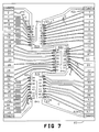
- Figure 7 illustrates another embodiment of this invention in which the single color nozzle plate of Figure 3 is modified in a printhead to accommodate three nozzle groups in a three chamber ink jet pen or recording head.
- Each nozzle group comprises 16 nozzles in two columns of 8 occupying the same positions in the individual columns as the correspondingly numbered nozzles in Figure 3.
- the nozzles of this printhead are arranged as three groups of 16 nozzles each, each group being associated with one of the three ink colors.
- the nozzles of each of the 16 nozzle groups are arranged as two columns of 8 nozzles separated by 10 logical print positions or dot rows.
- the three nozzle groups are arranged such that the middle group 62c is offset from the other two groups by 16 logical print or dot row positions.
- data for nozzles 17-32 should be shifted 16 logical print positions or dot rows from the rest of the nozzle data to adjust for the middle group offset.
- the middle nozzle group data With the middle nozzle group data shifted, the nozzle arrangement is the same as that of two columns of 25 nozzles separated by 10 dot rows, as seen in Figure 3.
- the nozzle resistors R are fired in a specific order to minimize internozzle crosstalk.
- the location of the nozzles has been set (Timing Offset) so that the dots in one of the 25 nozzle equivalent columns (after stagger correction of the middle nozzle group) will all be fired in the same vertical column when the head is moving at 30.48 cm/sec (12 in/sec) horizontally (with a 3.25 usec pulse width and 5.75 usec dead time).
- the dead time is adjusted to suit a selected carriage velocity.
- the dot firing sequence and relative orifice locations are shown in Table III.
- the indicated sequence should be used with the Shift Offset being data delay units.
- the resistors should be fired in the reverse sequence with the Shift Offset being data advance units.
- the resultant print will be a vertical column of dots as though all nozzles were located in a line at the physical position of nozzle 46 when the sequence started.
Applications Claiming Priority (2)
| Application Number | Priority Date | Filing Date | Title |
|---|---|---|---|
| US07/098,840 US4812859A (en) | 1987-09-17 | 1987-09-17 | Multi-chamber ink jet recording head for color use |
| US98840 | 1998-06-17 |
Publications (3)
| Publication Number | Publication Date |
|---|---|
| EP0308272A1 true EP0308272A1 (de) | 1989-03-22 |
| EP0308272B1 EP0308272B1 (de) | 1992-01-02 |
| EP0308272B2 EP0308272B2 (de) | 1994-06-15 |
Family
ID=22271152
Family Applications (1)
| Application Number | Title | Priority Date | Filing Date |
|---|---|---|---|
| EP88308650A Expired - Lifetime EP0308272B2 (de) | 1987-09-17 | 1988-09-19 | Mehrkammertintenstrahlaufzeichnungskopf für den Farbgebrauch |
Country Status (8)
| Country | Link |
|---|---|
| US (1) | US4812859A (de) |
| EP (1) | EP0308272B2 (de) |
| JP (1) | JP2863761B2 (de) |
| KR (1) | KR910007322B1 (de) |
| CA (1) | CA1328574C (de) |
| DE (1) | DE3867398D1 (de) |
| HK (1) | HK97193A (de) |
| SG (1) | SG393G (de) |
Cited By (13)
| Publication number | Priority date | Publication date | Assignee | Title |
|---|---|---|---|---|
| EP0495670A1 (de) * | 1991-01-18 | 1992-07-22 | Canon Kabushiki Kaisha | Tintenstrahlaufzeichnungskopf und Aufzeichnungsgerät damit versehen |
| EP0500939A1 (de) * | 1990-06-12 | 1992-09-02 | Samsung Electronics Co., Ltd. | Verfahren sowie druckkopf für mehrfarbigen tintenstrahldruck und herstellungsverfahren für diesen druckkopf |
| EP0517520A2 (de) * | 1991-06-07 | 1992-12-09 | Canon Kabushiki Kaisha | Farbstrahlaufzeichnungsverfahren und Vorrichtung |
| EP0526013A2 (de) * | 1991-07-30 | 1993-02-03 | Hewlett-Packard Company | Befestigung eines flexiblen Anschlusskreises an einem Tintenstrahlschreiber |
| EP0622207A2 (de) * | 1993-04-30 | 1994-11-02 | Hewlett-Packard Company | Gemeinsame Farbkassettenplattform für verschiedene Druckköpfe |
| EP0705695A3 (de) * | 1994-10-06 | 1997-01-22 | Hewlett Packard Co | Tintenzuführsystem |
| EP0705694A3 (de) * | 1994-10-06 | 1997-01-22 | Hewlett Packard Co | Drucksystem |
| EP0845359A2 (de) * | 1996-11-20 | 1998-06-03 | Lexmark International, Inc. | Heizelementchips für Matrixen mit grossen Abmessungen für thermische Tintenstrahldruckköpfe |
| EP0630752B1 (de) * | 1993-06-23 | 2000-09-06 | Canon Kabushiki Kaisha | Tintenstrahlaufzeichnungsverfahren und Gerät |
| EP1110732A3 (de) * | 1999-12-22 | 2002-06-12 | Eastman Kodak Company | Verstärkung der Ablenkung für kontinuierliche Tintenstrahldrucker |
| EP1112847A3 (de) * | 1999-12-30 | 2002-06-12 | Eastman Kodak Company | Kontinuierlicher Tintenstrahldrucker mit einem Kerbendeflektor |
| EP1275505A3 (de) * | 2001-07-11 | 2003-03-05 | Canon Kabushiki Kaisha | Flüssigkeitsausstosskopf |
| US6986566B2 (en) | 1999-12-22 | 2006-01-17 | Eastman Kodak Company | Liquid emission device |
Families Citing this family (99)
| Publication number | Priority date | Publication date | Assignee | Title |
|---|---|---|---|---|
| USRE37671E1 (en) | 1987-10-23 | 2002-04-30 | Hewlett-Packard Company | Printhead-carriage alignment and electrical interconnect lock-in mechanism |
| US4872027A (en) * | 1987-11-03 | 1989-10-03 | Hewlett-Packard Company | Printer having identifiable interchangeable heads |
| US4864328A (en) * | 1988-09-06 | 1989-09-05 | Spectra, Inc. | Dual mode ink jet printer |
| SG79276A1 (en) * | 1989-01-28 | 2001-03-20 | Canon Kk | Ink jet recording method and color ink jet recording device for practicing the same |
| US5237343A (en) * | 1989-03-24 | 1993-08-17 | Canon Kabushiki Kaisha | Ink jet head substrate, ink jet head having same and manufacturing method for ink jet head |
| US4940998A (en) * | 1989-04-04 | 1990-07-10 | Hewlett-Packard Company | Carriage for ink jet printer |
| JP2849113B2 (ja) * | 1989-04-28 | 1999-01-20 | キヤノン株式会社 | 記録装置および記録方法 |
| DE69033844T2 (de) * | 1989-04-28 | 2002-04-04 | Canon Kk | Bildverarbeitungseinrichtung |
| US5087930A (en) * | 1989-11-01 | 1992-02-11 | Tektronix, Inc. | Drop-on-demand ink jet print head |
| US5030971B1 (en) * | 1989-11-29 | 2000-11-28 | Xerox Corp | Precisely aligned mono- or multi-color roofshooter type printhead |
| US5079571A (en) * | 1990-05-25 | 1992-01-07 | Tektronix, Inc. | Interlaced printing using spaced print arrays |
| US5059984A (en) * | 1990-05-25 | 1991-10-22 | Tektronix, Inc. | Method and apparatus for interlaced multicolor printing |
| CA2049571C (en) * | 1990-10-19 | 2004-01-13 | Kent D. Vincent | High definition thermal ink-jet printer |
| EP0498293B1 (de) * | 1991-01-30 | 1996-10-30 | Canon Information Systems Research Australia Pty Ltd. | Strahldrucker mit Bläschen für Bildaufzeichnungsvorrichtung |
| US6019457A (en) * | 1991-01-30 | 2000-02-01 | Canon Information Systems Research Australia Pty Ltd. | Ink jet print device and print head or print apparatus using the same |
| AU657931B2 (en) * | 1991-01-30 | 1995-03-30 | Canon Kabushiki Kaisha | An integrally formed bubblejet print device |
| IT1245065B (it) * | 1991-04-15 | 1994-09-13 | Olivetti & Co Spa | Dispositivo rivelatore dell'inchiostro per un elemento di stampa a inchiostro liquido |
| US6406114B1 (en) | 1991-06-05 | 2002-06-18 | Canon Kabushiki Kaisha | Tonal product recorded by ink and having a plurality of pixels with plural tonal levels |
| US5430469A (en) * | 1991-06-05 | 1995-07-04 | Canon Kabushiki Kaisha | Tone recording method using ink recording head |
| US5552813A (en) * | 1992-03-11 | 1996-09-03 | Rohm Co., Ltd. | Ink jet head with nozzle arrangement to reduce viscous drag |
| US5600354A (en) * | 1992-04-02 | 1997-02-04 | Hewlett-Packard Company | Wrap-around flex with address and data bus |
| DE4214556A1 (de) * | 1992-04-28 | 1993-11-04 | Mannesmann Ag | Elektrothermischer tintendruckkopf |
| US5376958A (en) * | 1992-05-01 | 1994-12-27 | Hewlett-Packard Company | Staggered pens in color thermal ink-jet printer |
| US5442386A (en) * | 1992-10-13 | 1995-08-15 | Hewlett-Packard Company | Structure and method for preventing ink shorting of conductors connected to printhead |
| US5686948A (en) * | 1992-11-12 | 1997-11-11 | Graphic Utilities, Inc. | Method for refilling ink jet cartridges |
| AU5604694A (en) * | 1992-11-12 | 1994-06-08 | Graphic Utilities, Inc. | Method for refilling ink jet cartridges |
| JPH06164854A (ja) * | 1992-11-19 | 1994-06-10 | Canon Inc | 複写装置及びその方法 |
| US5481280A (en) * | 1992-11-30 | 1996-01-02 | Lam; Si-Ty | Color ink transfer printing |
| SG72611A1 (en) * | 1993-04-30 | 2000-05-23 | Hewlett Packard Co | Reliable contact and arrangement on plastic print cartridge |
| US5455610A (en) * | 1993-05-19 | 1995-10-03 | Xerox Corporation | Color architecture for an ink jet printer with overlapping arrays of ejectors |
| JP3229458B2 (ja) * | 1993-10-08 | 2001-11-19 | キヤノン株式会社 | 記録装置およびインクカートリッジ |
| DE4336416A1 (de) * | 1993-10-19 | 1995-08-24 | Francotyp Postalia Gmbh | Face-Shooter-Tintenstrahldruckkopf und Verfahren zu seiner Herstellung |
| US5975679A (en) * | 1993-10-29 | 1999-11-02 | Hewlett-Packard Company | Dot alignment in mixed resolution printer |
| US5764254A (en) * | 1993-10-29 | 1998-06-09 | Hewlett-Packard Company | Alignment of differently sized printheads in a printer |
| US6343857B1 (en) | 1994-02-04 | 2002-02-05 | Hewlett-Packard Company | Ink circulation in ink-jet pens |
| US5949461A (en) * | 1994-02-18 | 1999-09-07 | Nu-Kote Imaging International, Inc. | Ink refill bottle |
| JPH07276630A (ja) * | 1994-04-12 | 1995-10-24 | Rohm Co Ltd | インクジェットプリントヘッド及びインクジェットプリンタ |
| IT1273141B (it) * | 1994-04-14 | 1997-07-04 | Olivetti Canon Ind Spa | Metodo per migliorare la stampa di immagini grafiche e relativa apparecchiatura di stampa a matrice di punti a getto di inchiostro |
| JP3268937B2 (ja) * | 1994-04-14 | 2002-03-25 | キヤノン株式会社 | インクジェット記録ヘッド用基板及びそれを用いたヘッド |
| US5635968A (en) * | 1994-04-29 | 1997-06-03 | Hewlett-Packard Company | Thermal inkjet printer printhead with offset heater resistors |
| JP3135481B2 (ja) * | 1994-07-15 | 2001-02-13 | キヤノン株式会社 | プリント装置及びプリント方法 |
| US5602574A (en) * | 1994-08-31 | 1997-02-11 | Hewlett-Packard Company | Matrix pen arrangement for inkjet printing |
| JPH08156286A (ja) * | 1994-12-06 | 1996-06-18 | Olympus Optical Co Ltd | インクジェットプリンタ |
| US5654744A (en) * | 1995-03-06 | 1997-08-05 | Hewlett-Packard Company | Simultaneously printing with different sections of printheads for improved print quality |
| US5598191A (en) * | 1995-06-01 | 1997-01-28 | Xerox Corporation | Architecture for an ink jet printer with offset arrays of ejectors |
| DE69616665T2 (de) * | 1995-07-03 | 2002-08-01 | Oce Tech Bv | Tintenstrahldruckkopf |
| JPH09104113A (ja) * | 1995-10-12 | 1997-04-22 | Canon Inc | 記録装置及びその記録方法 |
| US5901425A (en) | 1996-08-27 | 1999-05-11 | Topaz Technologies Inc. | Inkjet print head apparatus |
| US5926195A (en) | 1996-11-22 | 1999-07-20 | Lexmark International Inc. | Ink jet printhead cartridge |
| AUPP653998A0 (en) * | 1998-10-16 | 1998-11-05 | Silverbrook Research Pty Ltd | Micromechanical device and method (ij46B) |
| AUPP653698A0 (en) * | 1998-10-16 | 1998-11-05 | Silverbrook Research Pty Ltd | Micromechanical fluid supply system (fluid08) |
| AUPP654098A0 (en) * | 1998-10-16 | 1998-11-05 | Silverbrook Research Pty Ltd | Micromechanical fluid supply system (fluid05) |
| US6017112A (en) * | 1997-11-04 | 2000-01-25 | Lexmark International, Inc. | Ink jet printing apparatus having a print cartridge with primary and secondary nozzles |
| KR100234438B1 (ko) * | 1997-11-20 | 1999-12-15 | 윤종용 | 잉크젯 프린트헤드 카트리지의 고속 인쇄 장치 |
| US6267472B1 (en) * | 1998-06-19 | 2001-07-31 | Lexmark International, Inc. | Ink jet heater chip module with sealant material |
| US20020001020A1 (en) * | 1998-06-19 | 2002-01-03 | James Michael Mrvos | Heater chip module for use in an ink jet printer |
| US6039439A (en) * | 1998-06-19 | 2000-03-21 | Lexmark International, Inc. | Ink jet heater chip module |
| US7216956B2 (en) * | 1998-10-16 | 2007-05-15 | Silverbrook Research Pty Ltd | Printhead assembly with power and ground connections along single edge |
| ATE367927T1 (de) * | 1998-10-16 | 2007-08-15 | Silverbrook Res Pty Ltd | Verfahren zur herstellung einer düse für einen tintenstrahldruckkopf |
| US6309052B1 (en) | 1999-04-30 | 2001-10-30 | Hewlett-Packard Company | High thermal efficiency ink jet printhead |
| US6231160B1 (en) | 1999-06-02 | 2001-05-15 | Hewlett-Packard Company | Ink jet printer having apparatus for reducing systematic print quality defects |
| US6499821B1 (en) * | 1999-07-22 | 2002-12-31 | Canon Kabushiki Kaisha | Ink jet printing apparatus and printing head |
| US6394579B1 (en) | 1999-08-24 | 2002-05-28 | Hewlett-Packard Company | Fluid ejecting device with varied nozzle spacing |
| US6139131A (en) * | 1999-08-30 | 2000-10-31 | Hewlett-Packard Company | High drop generator density printhead |
| US6234598B1 (en) | 1999-08-30 | 2001-05-22 | Hewlett-Packard Company | Shared multiple terminal ground returns for an inkjet printhead |
| US6491377B1 (en) * | 1999-08-30 | 2002-12-10 | Hewlett-Packard Company | High print quality printhead |
| US6616271B2 (en) * | 1999-10-19 | 2003-09-09 | Silverbrook Research Pty Ltd | Adhesive-based ink jet print head assembly |
| US6502920B1 (en) | 2000-02-04 | 2003-01-07 | Lexmark International, Inc | Ink jet print head having offset nozzle arrays |
| KR100374788B1 (ko) | 2000-04-26 | 2003-03-04 | 삼성전자주식회사 | 버블 젯 방식의 잉크 젯 프린트 헤드, 그 제조방법 및잉크 토출방법 |
| KR100397604B1 (ko) | 2000-07-18 | 2003-09-13 | 삼성전자주식회사 | 버블 젯 방식의 잉크 젯 프린트 헤드 및 그 제조방법 |
| ITTO20010266A1 (it) * | 2001-03-21 | 2002-09-23 | Olivetti I Jet Spa | Substrato per una testina di stampa termica a getto d'inchiostro, in particolare del tipo a colori, e testina di stampa incorporante tale su |
| US6616268B2 (en) | 2001-04-12 | 2003-09-09 | Lexmark International, Inc. | Power distribution architecture for inkjet heater chip |
| US6604812B2 (en) * | 2001-04-30 | 2003-08-12 | Hewlett-Packard Development Company, Lp | Print direction dependent firing frequency for improved edge quality |
| US6672697B2 (en) * | 2001-05-30 | 2004-01-06 | Eastman Kodak Company | Compensation method for overlapping print heads of an ink jet printer |
| US6533380B1 (en) * | 2001-09-12 | 2003-03-18 | Xerox Corporation | Method and apparatus for reducing neighbor cross-talk and increasing robustness of an acoustic printing system against isolated ejector failure |
| JP3922004B2 (ja) * | 2001-11-30 | 2007-05-30 | ブラザー工業株式会社 | インクジェットプリンタヘッド |
| US6747684B2 (en) | 2002-04-10 | 2004-06-08 | Hewlett-Packard Development Company, L.P. | Laser triggered inkjet firing |
| US6669330B2 (en) * | 2002-05-08 | 2003-12-30 | Agfa-Gevaert | Staggered multi-phase firing of nozzle heads for a printer |
| US7104623B2 (en) * | 2002-06-07 | 2006-09-12 | Hewlett-Packard Development Company, L.P. | Fluid ejection system with photosensor activation of ejection element |
| US7083250B2 (en) * | 2002-06-07 | 2006-08-01 | Hewlett-Packard Development Company, L.P. | Fluid ejection and scanning assembly with photosensor activation of ejection elements |
| US6705701B2 (en) | 2002-06-07 | 2004-03-16 | Hewlett-Packard Development Company, L.P. | Fluid ejection and scanning system with photosensor activation of ejection elements |
| US6799819B2 (en) | 2002-06-07 | 2004-10-05 | Hewlett-Packard Development Company, L.P. | Photosensor activation of an ejection element of a fluid ejection device |
| US6893120B2 (en) * | 2002-11-19 | 2005-05-17 | Lexmark International, Inc. | Multi-color ink reservoirs for ink jet printers |
| US7091134B1 (en) * | 2003-06-17 | 2006-08-15 | Novellus Systems, Inc. | Deposition of integrated circuit fabrication materials using a print head |
| US7198353B2 (en) * | 2004-06-30 | 2007-04-03 | Lexmark International, Inc. | Integrated black and colored ink printheads |
| US7396109B2 (en) * | 2005-10-28 | 2008-07-08 | Hewlett-Packard Development Company, L.P. | Inkjet printing system with high drop-weight yellow |
| US7771010B2 (en) * | 2006-02-03 | 2010-08-10 | Rr Donnelley | Apparatus for printing using a plurality of printing cartridges |
| US7918530B2 (en) * | 2006-02-03 | 2011-04-05 | Rr Donnelley | Apparatus and method for cleaning an inkjet printhead |
| US7967407B2 (en) * | 2006-02-03 | 2011-06-28 | R.R. Donnelley | Use of a sense mark to control a printing system |
| JP4760907B2 (ja) * | 2006-06-23 | 2011-08-31 | コニカミノルタエムジー株式会社 | インクジェット記録装置 |
| US7712883B2 (en) * | 2006-07-26 | 2010-05-11 | Hewlett-Packard Development Company, L.P. | Print cartridge body |
| US20090021542A1 (en) * | 2007-06-29 | 2009-01-22 | Kanfoush Dan E | System and method for fluid transmission and temperature regulation in an inkjet printing system |
| JP5043539B2 (ja) * | 2007-07-02 | 2012-10-10 | キヤノン株式会社 | 液体噴射記録ヘッドの製造方法 |
| US8517491B2 (en) * | 2010-02-19 | 2013-08-27 | Canon Kabushiki Kaisha | Printing apparatus and driving method of a liquid ejecting head |
| EP2741917B1 (de) | 2011-08-12 | 2019-05-22 | R. R. Donnelley & Sons Company | Vorrichtung und verfahren zum anordnen von tintenstrahlpatronen in einem träger |
| US8888208B2 (en) | 2012-04-27 | 2014-11-18 | R.R. Donnelley & Sons Company | System and method for removing air from an inkjet cartridge and an ink supply line |
| US10137691B2 (en) | 2016-03-04 | 2018-11-27 | R.R. Donnelley & Sons Company | Printhead maintenance station and method of operating same |
| CN207291314U (zh) | 2016-05-09 | 2018-05-01 | R.R.当纳利父子公司 | 油墨供应单元 |
| WO2019094022A1 (en) * | 2017-11-10 | 2019-05-16 | Hewlett-Packard Development Company, L.P. | Fluidic cartridges |
Citations (5)
| Publication number | Priority date | Publication date | Assignee | Title |
|---|---|---|---|---|
| DE3524000A1 (de) * | 1984-07-05 | 1986-01-16 | Canon K.K., Tokio/Tokyo | Fluessigkeitsstrahlschreibkopf |
| DE3612676A1 (de) * | 1985-04-15 | 1986-10-16 | Sharp K.K., Osaka | Druckkopf fuer tintenstrahl-farbdrucker |
| EP0216176A1 (de) * | 1985-08-30 | 1987-04-01 | Siemens Aktiengesellschaft | Anordnung für die Austrittsöffnungen im Druckkopf einer Mehrfarben-Tintenschreibeinrichtung |
| US4683481A (en) * | 1985-12-06 | 1987-07-28 | Hewlett-Packard Company | Thermal ink jet common-slotted ink feed printhead |
| EP0261764A1 (de) * | 1986-07-01 | 1988-03-30 | Hewlett-Packard Company | Tintenvorratsbehälter mit absorbierendem Schaumstoff für eine Tintenstrahldruckvorrichtung |
Family Cites Families (8)
| Publication number | Priority date | Publication date | Assignee | Title |
|---|---|---|---|---|
| JPS5563278A (en) * | 1978-11-02 | 1980-05-13 | Ricoh Co Ltd | Multi-head ink jet recorder |
| DE2925812C2 (de) * | 1979-06-26 | 1982-10-21 | Siemens AG, 1000 Berlin und 8000 München | Tintendruckeinrichtung zum mehrfarbigen Bedrucken eines Aufzeichnungträgers |
| US4611219A (en) * | 1981-12-29 | 1986-09-09 | Canon Kabushiki Kaisha | Liquid-jetting head |
| JPS6021258A (ja) * | 1983-07-18 | 1985-02-02 | Canon Inc | 液滴吐出装置 |
| IT1162919B (it) * | 1983-07-20 | 1987-04-01 | Olivetti & Co Spa | Dispositivo di scirttura a getto di inchiostro particolarmente per stampanti ad alta velocita |
| US4564846A (en) * | 1984-10-26 | 1986-01-14 | Kiwi Coders Corporation | Drop on demand dot matrix printing head |
| US4665409A (en) * | 1984-11-29 | 1987-05-12 | Siemens Aktiengesellschaft | Write head for ink printer devices |
| US4734717A (en) * | 1986-12-22 | 1988-03-29 | Eastman Kodak Company | Insertable, multi-array print/cartridge |
-
1987
- 1987-09-17 US US07/098,840 patent/US4812859A/en not_active Expired - Lifetime
-
1988
- 1988-08-08 CA CA000574124A patent/CA1328574C/en not_active Expired - Fee Related
- 1988-09-12 JP JP63228275A patent/JP2863761B2/ja not_active Expired - Lifetime
- 1988-09-16 KR KR1019880011985A patent/KR910007322B1/ko not_active IP Right Cessation
- 1988-09-19 DE DE8888308650T patent/DE3867398D1/de not_active Expired - Lifetime
- 1988-09-19 EP EP88308650A patent/EP0308272B2/de not_active Expired - Lifetime
-
1993
- 1993-01-04 SG SG3/93A patent/SG393G/en unknown
- 1993-09-16 HK HK971/93A patent/HK97193A/xx not_active IP Right Cessation
Patent Citations (5)
| Publication number | Priority date | Publication date | Assignee | Title |
|---|---|---|---|---|
| DE3524000A1 (de) * | 1984-07-05 | 1986-01-16 | Canon K.K., Tokio/Tokyo | Fluessigkeitsstrahlschreibkopf |
| DE3612676A1 (de) * | 1985-04-15 | 1986-10-16 | Sharp K.K., Osaka | Druckkopf fuer tintenstrahl-farbdrucker |
| EP0216176A1 (de) * | 1985-08-30 | 1987-04-01 | Siemens Aktiengesellschaft | Anordnung für die Austrittsöffnungen im Druckkopf einer Mehrfarben-Tintenschreibeinrichtung |
| US4683481A (en) * | 1985-12-06 | 1987-07-28 | Hewlett-Packard Company | Thermal ink jet common-slotted ink feed printhead |
| EP0261764A1 (de) * | 1986-07-01 | 1988-03-30 | Hewlett-Packard Company | Tintenvorratsbehälter mit absorbierendem Schaumstoff für eine Tintenstrahldruckvorrichtung |
Cited By (24)
| Publication number | Priority date | Publication date | Assignee | Title |
|---|---|---|---|---|
| EP0500939A1 (de) * | 1990-06-12 | 1992-09-02 | Samsung Electronics Co., Ltd. | Verfahren sowie druckkopf für mehrfarbigen tintenstrahldruck und herstellungsverfahren für diesen druckkopf |
| EP0500939A4 (en) * | 1990-06-12 | 1992-11-04 | Jury Grigorievich Eremin | Method and printing head for multicolour ink-jet printing and method of making said head |
| EP0495670A1 (de) * | 1991-01-18 | 1992-07-22 | Canon Kabushiki Kaisha | Tintenstrahlaufzeichnungskopf und Aufzeichnungsgerät damit versehen |
| EP0517520A2 (de) * | 1991-06-07 | 1992-12-09 | Canon Kabushiki Kaisha | Farbstrahlaufzeichnungsverfahren und Vorrichtung |
| EP0517520A3 (en) * | 1991-06-07 | 1992-12-30 | Canon Kabushiki Kaisha | Ink-jet recording method and ink-jet recording apparatus |
| US5650803A (en) * | 1991-06-07 | 1997-07-22 | Canon Kabushiki Kaisha | Ink-jet recording method and ink-jet recording apparatus |
| EP0526013A3 (de) * | 1991-07-30 | 1994-03-09 | Hewlett Packard Co | |
| EP0526013A2 (de) * | 1991-07-30 | 1993-02-03 | Hewlett-Packard Company | Befestigung eines flexiblen Anschlusskreises an einem Tintenstrahlschreiber |
| US5638101A (en) * | 1992-04-02 | 1997-06-10 | Hewlett-Packard Company | High density nozzle array for inkjet printhead |
| EP0622207A3 (de) * | 1993-04-30 | 1995-04-19 | Hewlett Packard Co | Gemeinsame Farbkassettenplattform für verschiedene Druckköpfe. |
| EP0622207A2 (de) * | 1993-04-30 | 1994-11-02 | Hewlett-Packard Company | Gemeinsame Farbkassettenplattform für verschiedene Druckköpfe |
| EP0630752B1 (de) * | 1993-06-23 | 2000-09-06 | Canon Kabushiki Kaisha | Tintenstrahlaufzeichnungsverfahren und Gerät |
| EP0705694A3 (de) * | 1994-10-06 | 1997-01-22 | Hewlett Packard Co | Drucksystem |
| EP0705695A3 (de) * | 1994-10-06 | 1997-01-22 | Hewlett Packard Co | Tintenzuführsystem |
| EP0845359A2 (de) * | 1996-11-20 | 1998-06-03 | Lexmark International, Inc. | Heizelementchips für Matrixen mit grossen Abmessungen für thermische Tintenstrahldruckköpfe |
| EP0845359A3 (de) * | 1996-11-20 | 1999-03-10 | Lexmark International, Inc. | Heizelementchips für Matrixen mit grossen Abmessungen für thermische Tintenstrahldruckköpfe |
| EP1110732A3 (de) * | 1999-12-22 | 2002-06-12 | Eastman Kodak Company | Verstärkung der Ablenkung für kontinuierliche Tintenstrahldrucker |
| US6497510B1 (en) | 1999-12-22 | 2002-12-24 | Eastman Kodak Company | Deflection enhancement for continuous ink jet printers |
| US6761437B2 (en) | 1999-12-22 | 2004-07-13 | Eastman Kodak Company | Apparatus and method of enhancing fluid deflection in a continuous ink jet printhead |
| US6986566B2 (en) | 1999-12-22 | 2006-01-17 | Eastman Kodak Company | Liquid emission device |
| EP1112847A3 (de) * | 1999-12-30 | 2002-06-12 | Eastman Kodak Company | Kontinuierlicher Tintenstrahldrucker mit einem Kerbendeflektor |
| EP1275505A3 (de) * | 2001-07-11 | 2003-03-05 | Canon Kabushiki Kaisha | Flüssigkeitsausstosskopf |
| US7036909B2 (en) | 2001-07-11 | 2006-05-02 | Canon Kabushiki Kaisha | Liquid ejection head |
| US7384130B2 (en) | 2001-07-11 | 2008-06-10 | Canon Kabushiki Kaisha | Liquid ejection head |
Also Published As
| Publication number | Publication date |
|---|---|
| EP0308272B1 (de) | 1992-01-02 |
| EP0308272B2 (de) | 1994-06-15 |
| HK97193A (en) | 1993-09-24 |
| SG393G (en) | 1993-03-12 |
| CA1328574C (en) | 1994-04-19 |
| KR910007322B1 (ko) | 1991-09-25 |
| JPH01110965A (ja) | 1989-04-27 |
| US4812859A (en) | 1989-03-14 |
| KR890004863A (ko) | 1989-05-10 |
| DE3867398D1 (de) | 1992-02-13 |
| JP2863761B2 (ja) | 1999-03-03 |
Similar Documents
| Publication | Publication Date | Title |
|---|---|---|
| US4812859A (en) | Multi-chamber ink jet recording head for color use | |
| US4833491A (en) | Thermal ink jet printer adapted to operate in monochrome, highlight or process color modes | |
| US4908638A (en) | Ink jet marking head having multicolor capability | |
| EP1827847B1 (de) | Flüssigkeitsausstossvorrichtung und düsenreihenanordnung | |
| CA1158705A (en) | Ink printing device for multi-colored printing of a recording medium | |
| US5463412A (en) | Liquid jet recording head with multiple liquid chambers | |
| JP4210057B2 (ja) | インクジェットプリントカートリッジおよびその製造方法 | |
| EP1145855B1 (de) | Druckkopf-Substrat mit Tintentropfenerzeugern gruppiert abwechselnd an einer und beiden Seiten der Tintenzufuhrkanäle | |
| JP2003127439A (ja) | インクジェット記録ヘッド、インクジェット記録装置、およびインクジェット記録方法 | |
| KR0161793B1 (ko) | 잉크 제트 기록 장치 및 그에 사용되는 잉크 탱크 | |
| JP3329801B2 (ja) | インクジェット式記録ヘッド | |
| CN111845073A (zh) | 打印设备及方法 | |
| JPH10202851A (ja) | インクジェット記録装置 | |
| EP1644197B1 (de) | Flüssigkeitausstossvorrichtung | |
| US4965595A (en) | Printing head of color ink jet printer | |
| JPH09254413A (ja) | 階調記録に用いるインクジェットヘッド、インクジェットヘッドカートリッジ、インクジェット装置およびインクジェット記録方法 | |
| JP3039533B2 (ja) | インク吐出型印刷装置 | |
| EP1145854B1 (de) | Druckkopf-Substrat mit Tintentropfenerzeugern aufgeteilt in Gruppen die beide Seitenkanten eines Tintenzuführkanals umfassen | |
| JP3578196B2 (ja) | インクジェット式記録ヘッド | |
| JP2706466B2 (ja) | インクジェット記録装置,インクジェット記録ヘッド及びその記録方法 | |
| JPH07290711A (ja) | インクジェットヘッド、インクジェットヘッドカートリッジ、インクジェットヘッドキット、インクジェット記録装置、インクジェットヘッドの製造方法およびインクの注入方法 | |
| JPH03244550A (ja) | カラーインクジェットヘッド | |
| JPH1044440A (ja) | インクジェットヘッドおよびインクジェットプリント装置 | |
| JP2001301167A (ja) | インクジェット式記録ヘッド及びインクジェット式記録装置 | |
| JP2001191524A (ja) | インクジェット式記録ヘッド及びインクジェット式記録装置 |
Legal Events
| Date | Code | Title | Description |
|---|---|---|---|
| PUAI | Public reference made under article 153(3) epc to a published international application that has entered the european phase |
Free format text: ORIGINAL CODE: 0009012 |
|
| AK | Designated contracting states |
Kind code of ref document: A1 Designated state(s): DE FR GB IT |
|
| 17P | Request for examination filed |
Effective date: 19890330 |
|
| 17Q | First examination report despatched |
Effective date: 19900911 |
|
| GRAA | (expected) grant |
Free format text: ORIGINAL CODE: 0009210 |
|
| AK | Designated contracting states |
Kind code of ref document: B1 Designated state(s): DE FR GB IT |
|
| REF | Corresponds to: |
Ref document number: 3867398 Country of ref document: DE Date of ref document: 19920213 |
|
| ET | Fr: translation filed | ||
| ITF | It: translation for a ep patent filed |
Owner name: SOCIETA' ITALIANA BREVETTI S.P.A. |
|
| PLBI | Opposition filed |
Free format text: ORIGINAL CODE: 0009260 |
|
| 26 | Opposition filed |
Opponent name: BSG TECHNISCHE BERATUNGS-GESELLSCHAFT MBH, ESSLING Effective date: 19921002 Opponent name: MANNESMANN AG Effective date: 19920930 |
|
| PLAB | Opposition data, opponent's data or that of the opponent's representative modified |
Free format text: ORIGINAL CODE: 0009299OPPO |
|
| R26 | Opposition filed (corrected) |
Opponent name: MANNESMANN AG * 921002 BSG TECHNISCHE BERATUNGS-GE Effective date: 19920930 |
|
| PUAA | Information related to the publication of a b2 document modified |
Free format text: ORIGINAL CODE: 0009299PMAP |
|
| PUAH | Patent maintained in amended form |
Free format text: ORIGINAL CODE: 0009272 |
|
| STAA | Information on the status of an ep patent application or granted ep patent |
Free format text: STATUS: PATENT MAINTAINED AS AMENDED |
|
| 27A | Patent maintained in amended form |
Effective date: 19940615 |
|
| AK | Designated contracting states |
Kind code of ref document: B2 Designated state(s): IT |
|
| ET3 | Fr: translation filed ** decision concerning opposition | ||
| ITF | It: translation for a ep patent filed |
Owner name: SOCIETA' ITALIANA BREVETTI S.P.A. |
|
| R27A | Patent maintained in amended form (corrected) |
Effective date: 19940615 |
|
| REG | Reference to a national code |
Ref country code: GB Ref legal event code: 732E |
|
| REG | Reference to a national code |
Ref country code: FR Ref legal event code: TP |
|
| REG | Reference to a national code |
Ref country code: GB Ref legal event code: IF02 |
|
| PGFP | Annual fee paid to national office [announced via postgrant information from national office to epo] |
Ref country code: GB Payment date: 20070926 Year of fee payment: 20 |
|
| PGFP | Annual fee paid to national office [announced via postgrant information from national office to epo] |
Ref country code: IT Payment date: 20070927 Year of fee payment: 20 Ref country code: DE Payment date: 20071031 Year of fee payment: 20 |
|
| PGFP | Annual fee paid to national office [announced via postgrant information from national office to epo] |
Ref country code: FR Payment date: 20070917 Year of fee payment: 20 |
|
| PLAB | Opposition data, opponent's data or that of the opponent's representative modified |
Free format text: ORIGINAL CODE: 0009299OPPO |
|
| REG | Reference to a national code |
Ref country code: GB Ref legal event code: PE20 Expiry date: 20080918 |
|
| PG25 | Lapsed in a contracting state [announced via postgrant information from national office to epo] |
Ref country code: GB Free format text: LAPSE BECAUSE OF EXPIRATION OF PROTECTION Effective date: 20080918 |