EP0306761B1 - Embrayage roue libre à corps de coincement - Google Patents
Embrayage roue libre à corps de coincement Download PDFInfo
- Publication number
- EP0306761B1 EP0306761B1 EP88113646A EP88113646A EP0306761B1 EP 0306761 B1 EP0306761 B1 EP 0306761B1 EP 88113646 A EP88113646 A EP 88113646A EP 88113646 A EP88113646 A EP 88113646A EP 0306761 B1 EP0306761 B1 EP 0306761B1
- Authority
- EP
- European Patent Office
- Prior art keywords
- overrunning clutch
- clutch according
- spring
- cage
- bend
- Prior art date
- Legal status (The legal status is an assumption and is not a legal conclusion. Google has not performed a legal analysis and makes no representation as to the accuracy of the status listed.)
- Expired - Lifetime
Links
- 239000000463 material Substances 0.000 claims description 9
- 230000008878 coupling Effects 0.000 claims description 4
- 238000010168 coupling process Methods 0.000 claims description 4
- 238000005859 coupling reaction Methods 0.000 claims description 4
- 230000000717 retained effect Effects 0.000 claims 1
- 238000009434 installation Methods 0.000 description 3
- 230000004323 axial length Effects 0.000 description 2
- 230000037431 insertion Effects 0.000 description 2
- 238000003780 insertion Methods 0.000 description 2
- 238000004519 manufacturing process Methods 0.000 description 2
- 230000008719 thickening Effects 0.000 description 2
- 230000005540 biological transmission Effects 0.000 description 1
- 230000002093 peripheral effect Effects 0.000 description 1
- 238000005096 rolling process Methods 0.000 description 1
- 239000007787 solid Substances 0.000 description 1
- 239000000725 suspension Substances 0.000 description 1
Images

Classifications
-
- F—MECHANICAL ENGINEERING; LIGHTING; HEATING; WEAPONS; BLASTING
- F16—ENGINEERING ELEMENTS AND UNITS; GENERAL MEASURES FOR PRODUCING AND MAINTAINING EFFECTIVE FUNCTIONING OF MACHINES OR INSTALLATIONS; THERMAL INSULATION IN GENERAL
- F16D—COUPLINGS FOR TRANSMITTING ROTATION; CLUTCHES; BRAKES
- F16D41/00—Freewheels or freewheel clutches
- F16D41/06—Freewheels or freewheel clutches with intermediate wedging coupling members between an inner and an outer surface
- F16D41/069—Freewheels or freewheel clutches with intermediate wedging coupling members between an inner and an outer surface the intermediate members wedging by pivoting or rocking, e.g. sprags
- F16D41/07—Freewheels or freewheel clutches with intermediate wedging coupling members between an inner and an outer surface the intermediate members wedging by pivoting or rocking, e.g. sprags between two cylindrical surfaces
Definitions
- the invention relates to a one-way clutch with clamping bodies, which are held captive in flat edge surfaces of pockets of a one-piece single cage, each with a resilient element, which has an axial spring section lying next to the clamping body, an extension of the spring section acting on the clamping body in the coupling direction, and an extension on the single cage supporting support area.
- DE-AS 1 915 567 Such a one-way clutch is described in DE-AS 1 915 567.
- the spring elements according to DE-AS 1 915 567 are formed by coil springs made of wire material. These coil springs are loosely placed on the lugs of the cage, which protrude into the pockets. The clock spring thus takes up space within the pocket. The largest axial length of the pocket is therefore not fully usable by the clamping body.
- DE-AS 20 27 763 describes a freewheel with sprags, in which the spring elements are formed by leaf springs. These leaf springs are located in the circumferential direction between the clamping bodies and are held on the cage by means of snap members between the clamping bodies. This arrangement of the suspension elements limits the use of the installation space by the clamping bodies in the circumferential direction.
- the object of the invention is to propose a one-way clutch of the type mentioned, in which the assembly of the resilient elements and the clamping body is simplified and in which the resilient elements are arranged so that the clamping body can largely utilize the space axially and in the circumferential direction.
- the above object is achieved in a one-way clutch of the type mentioned at the outset in that the spring element consists of flat material and the spring section is formed by at least one bend in the flat material, in that the bend is in the space between the radial plane in which the end-face outer surface of the single cage lies , and runs in the radial plane in which the edges of the pockets with the greatest axial clear width are located near this outer surface, and that the holding area is fixed to the single cage in a self-retaining manner.
- the spring element made of flat material can also be easily handled by machine. After insertion into the cage, the spring element is held captively on the cage even before the clamping bodies are inserted. This makes assembly considerably easier.
- the bend forming the spring section lies outside the pocket, axially next to the clamping body and radially next to the edge of the cage, that is to say in an area which the clamping body cannot take anyway. In this way, as far as possible, the use of the installation space by the clamping bodies is possible.
- the clamping bodies can therefore be arranged close to one another in the circumferential direction, since the spring section of the spring element does not run between them. In the axial direction, the clamping bodies can use the maximum clear width of the bag.
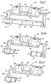
- a single cage (I) has shelves (2, 3). It is provided with pockets (4) for receiving sprags (5).
- the pockets (4) are delimited by flat edge surfaces (6,7) and front edges (8,9).
- the greatest axial clear width (L) exists between the front edges (8, 9).
- the end face of the one flange (2) and thus the single cage (1) lies in a radial plane (10).
- the other end outer surface of the single cage (1) and thus the rim (3) lies in a radial plane (11).
- the front edges (8) of the pockets (4) run in a radial plane (12) in the area of the greatest axial clear width (L).
- the front edges (9) are accordingly on a radial plane (13).
- contact surfaces (14) protruding slightly into the pockets (4) are formed on the edges (8).
- Corresponding contact surfaces (15) are formed on the edges (9).
- the single cage (1) is punched, rolled and welded from flat material, for example.
- Crosspieces (16) run between the pockets (4). In these axial slots (17) are provided which interrupt the webs (16) so that they assume a corresponding bend during the manufacturing step of rolling, i.e. the cage has no polygon shape.
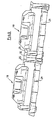
- a spring element (18) is assigned to each clamping body (5).
- the spring element (18) is bent from resilient flat material. It has a holding area (19), a spring section (20) adjoining this and an extension (21) which acts on the clamping body (5) in the coupling direction with the spring force originating from the spring section (20).
- the holding area (19) is formed by a U-shaped tab (22) on which a tongue (23) is formed.
- the tab (22) is provided with an angled portion (24) on one leg.
- One leg of the tab (22) is connected to the spring section (20) via a web (25).
- the tab (22) is practically as long as the slot (17). This ensures that the spring element (18) is axially fixed in the slot (17).
- it is provided with bevels (26).
- the spring element (18) can be fixed in a simple manner on the single cage (1). For this purpose, it is inserted axially into the cage (I) and then inserted radially into the slot (17) until the bend (24) and the web (25) bear against the web (16) on the inside. The tongue (23) snaps onto the outside of the web (16). A certain spring force of the tab (22) improves the fit.
- the spring-loaded elements are thus fixed to the single cage (1) even when the clamping bodies (5) have not yet been inserted. After the spring elements (18) have snapped into the slots (17), the clamping bodies (5) are pushed into the pockets (4), the clamping bodies (5) then abutting the extensions (21) in such a way that they are coupled in from the Spring force of the spring sections (20) are applied.
- the spring section (20) is formed by a V-shaped bend (27, 28).
- the bend (27) lies in the space between the radial plane (10) and the radial plane (12).
- the bend (28) lies in the space between the radial plane (11) and the radial plane (13).
- the bends (27, 28) thus lie next to the clamping bodies (5). So you do not limit the possible axial length of the clamping body. This is advantageous if the clamping bodies (5) are to fill the individual cage (1) as far as possible for the transmission of high forces. Since the spring-effective bends (27, 28) are also not arranged between adjacent clamping bodies (5), extensive use of the installation space of the individual cage (1) is also possible in the circumferential direction.
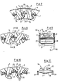
- the extensions (21) of the bends (27, 28) are formed by a continuous crosspiece (29) which is stiffened by a rib (30) and has a projection (31) in the center for bearing against it Has clamp body (5).
- the extensions (21) of the bends (27, 28) are separated.
- a spring-effective bend is only provided on one side.
- FIG. 6 shows a double spring element which consists of two spring elements (18) corresponding to FIG. 3, which are connected to one another via a connection (32).
- This double spring element is used in a single cage with two rings of sprags.
- a multiple spring element could also be constructed accordingly.
- FIG. 7 shows the single cage (1) installed between two running surfaces (33, 34).
- the spring elements (18) press with their extensions (21) in the coupling direction on the clamping body (5).
- the clamping bodies (5) are solid bodies without slots, bores or bearing journals. They are stored in the pocket (4) with a thickening (35).
- the extension (21) presses on the clamping body (5) in such a way that the thickening (35) is supported on the peripheral surface (7) of the single cage (1), which is seen in the circumferential direction.
- FIGS. 8 and 9 show the single cage (1) when it is not installed between the running surfaces.
- the clamping bodies (5) are pivoted accordingly and are thus held captive.
- the bends (27, 28) lie between the radial planes (10, 12 and 11, 13) (see FIG. 9) and there between the clamping bodies (5) (see FIG. 8).
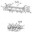
- FIGS. 10 and 11 show a spring element (18) which engages around the clamping body (5) assigned to it.
- the crosspiece (29) acts here on the clamping body (5).
- the crossbar has a bend (36).
- the projection (31), which bears against the clamping body (5), is provided in the center of the latter. A self-alignment of the clamping body (5) is thereby achieved.
- the holding area (19) is fastened to the slot (17). If the single cage (1) does not have the slots (17), then a spring element (18) according to FIGS. 12 and 13 can be used.
- the holding area (19) of this spring element (18) forms a closed frame (37), the opening (38) of which is aligned with the pocket (4) in the state defined on the individual cage (1) (cf. FIG. 13). Double hooks (39, 40) are formed on both sides of the frame (37).
- the spring element (18) is pressed with the double hook (39, 40) through the relevant pocket (4).
- the frame (37) then lies against the inside of the webs (16) in the vicinity of the pocket (4).
- the double hooks (39, 40) overlap the webs (16) at the top. Snap-in of the flat double hooks (39, 40) is possible due to the spring elasticity in the areas (41) of the frame (37).
- the clamping bodies (5) are inserted into the pockets (4). You are then held captive by the crossbar (29).
- the spring section (27 or 28) need not be formed by only one bend in the flat material. It can also have several bends, so that it has, for example, a W or Z shape.
Claims (15)
Applications Claiming Priority (2)
| Application Number | Priority Date | Filing Date | Title |
|---|---|---|---|
| DE3729632 | 1987-09-04 | ||
| DE19873729632 DE3729632A1 (de) | 1987-09-04 | 1987-09-04 | Freilaufkupplung mit klemmkoerpern |
Publications (2)
| Publication Number | Publication Date |
|---|---|
| EP0306761A1 EP0306761A1 (fr) | 1989-03-15 |
| EP0306761B1 true EP0306761B1 (fr) | 1990-06-13 |
Family
ID=6335243
Family Applications (1)
| Application Number | Title | Priority Date | Filing Date |
|---|---|---|---|
| EP88113646A Expired - Lifetime EP0306761B1 (fr) | 1987-09-04 | 1988-08-23 | Embrayage roue libre à corps de coincement |
Country Status (7)
| Country | Link |
|---|---|
| US (1) | US4867292A (fr) |
| EP (1) | EP0306761B1 (fr) |
| JP (1) | JPH0656187B2 (fr) |
| AU (1) | AU608358B2 (fr) |
| BR (1) | BR8804546A (fr) |
| DE (2) | DE3729632A1 (fr) |
| ES (1) | ES2015102B3 (fr) |
Cited By (1)
| Publication number | Priority date | Publication date | Assignee | Title |
|---|---|---|---|---|
| DE10236154A1 (de) * | 2002-08-07 | 2004-02-19 | Ina-Schaeffler Kg | Freilaufkupplung |
Families Citing this family (23)
| Publication number | Priority date | Publication date | Assignee | Title |
|---|---|---|---|---|
| US5064037A (en) * | 1990-03-01 | 1991-11-12 | Long Jr Thomas F | One-way acting sprag clutch with centrifugal disengagement from the outer race |
| US5146618A (en) * | 1990-05-24 | 1992-09-08 | Wenner Jeffrey W | Automotive radio support and conversion apparatus |
| US5070976A (en) * | 1990-12-27 | 1991-12-10 | Dana Corporation | Sprag retainer |
| US5101946A (en) * | 1991-09-03 | 1992-04-07 | General Motors Corporation | Cage phased roller clutch with improved roller shifting |
| DE4206438A1 (de) * | 1992-02-29 | 1993-09-02 | Scintilla Ag | Handgefuehrte, kraftgetriebene werkzeugmaschine |
| BG51056A3 (en) * | 1992-04-28 | 1993-01-15 | Dimitar B Filipov | Idle run clutch |
| DE9310178U1 (de) * | 1993-07-08 | 1993-09-02 | Schaeffler Waelzlager Kg | Klemmkörperfreilauf |
| US5383542A (en) * | 1993-12-27 | 1995-01-24 | Ford Motor Company | Overrunning clutch |
| US5607036A (en) | 1995-03-03 | 1997-03-04 | Borg-Warner Automotive, Inc. | One-way clutch with stretchable spring member |
| JPH0942329A (ja) * | 1995-07-24 | 1997-02-10 | Nsk Warner Kk | ワンウエイクラッチ組立体 |
| JP2003083366A (ja) * | 2001-06-25 | 2003-03-19 | Nsk Warner Kk | ワンウェイクラッチ装置 |
| DE10310225A1 (de) * | 2003-03-08 | 2004-09-16 | Ina-Schaeffler Kg | Freilaufkupplung |
| EP1848897A1 (fr) * | 2005-02-15 | 2007-10-31 | Aktiebolaget SKF (publ) | Dispositif de roulement codeur et machine tournante |
| DE102005046800A1 (de) * | 2005-09-30 | 2007-04-05 | Schaeffler Kg | Freilaufkäfigring |
| DE102005046896A1 (de) | 2005-09-30 | 2007-04-05 | Schaeffler Kg | Freilaufkupplung |
| FR2902699B1 (fr) * | 2006-06-26 | 2010-10-22 | Skf Ab | Dispositif de butee de suspension et jambe de force. |
| FR2906587B1 (fr) * | 2006-10-03 | 2009-07-10 | Skf Ab | Dispositif de galet tendeur. |
| FR2906858B1 (fr) * | 2006-10-04 | 2008-12-05 | Skf Ab | Dispositif de poulie debrayable. |
| FR2910129B1 (fr) * | 2006-12-15 | 2009-07-10 | Skf Ab | Dispositif de palier a roulement instrumente |
| FR2913081B1 (fr) * | 2007-02-27 | 2009-05-15 | Skf Ab | Dispositif de poulie debrayable |
| DE102008030017B4 (de) * | 2008-06-24 | 2016-07-21 | Schaeffler Technologies AG & Co. KG | Metallkäfige für Klemmkörperfreilaufkupplungen |
| US8186699B2 (en) | 2008-12-18 | 2012-05-29 | Steve Green | Wheelchair lever drive system |
| US9121495B2 (en) | 2013-03-15 | 2015-09-01 | Dayco Ip Holdings, Llc | Accessory drive decoupler |
Family Cites Families (23)
| Publication number | Priority date | Publication date | Assignee | Title |
|---|---|---|---|---|
| US2630896A (en) * | 1951-08-02 | 1953-03-10 | Adiel Y Dodge | One-way clutch |
| DE1142254B (de) * | 1951-12-24 | 1963-01-10 | Borg Warner | Freilaufkupplung |
| US2824635A (en) * | 1951-12-24 | 1958-02-25 | Borg Warner | One-way engaging device |
| US2744598A (en) * | 1952-02-07 | 1956-05-08 | Borg Warner | One-way engaging mechanism |
| US2753027A (en) * | 1952-02-07 | 1956-07-03 | Borg Warner | One-way engaging mechanism |
| US2835363A (en) * | 1952-11-15 | 1958-05-20 | Nat Supply Co | Overrunning clutch |
| US3087588A (en) * | 1958-06-09 | 1963-04-30 | Gen Motors Corp | One-way engaging mechanism |
| US3031053A (en) * | 1959-03-06 | 1962-04-24 | Gen Motors Corp | One-way clutch |
| DE1915567B2 (de) * | 1969-03-27 | 1972-03-16 | Ringspann Albrecht Maurer Kg, 6380 Bad Homburg | Freilaufkupplung mit klemmstuecken |
| GB1314529A (en) * | 1969-06-06 | 1973-04-26 | Renold Ltd | Sprag clutches |
| DE6923286U (de) * | 1969-06-11 | 1970-11-12 | Schaeffler Ohg Industriewerk | Klemmrollen - freilauf |
| FR2147416A5 (fr) * | 1971-07-27 | 1973-03-09 | Ferodo Sa | |
| SE7407449L (fr) * | 1973-07-20 | 1975-01-21 | Ciba Geigy Ag | |
| US3863742A (en) * | 1973-08-08 | 1975-02-04 | Torrington Co | Retainer for overrunning clutch |
| JPS51117956U (fr) * | 1975-03-18 | 1976-09-24 | ||
| DE2714046C2 (de) * | 1977-03-30 | 1985-12-05 | Stieber Division Der Borg-Warner Gmbh, 6900 Heidelberg | Klemmkörper-Freilaufkupplung mit einem Käfig zur Aufnahme und Halterung der Klemmkörper |
| FR2456258A1 (fr) * | 1979-05-10 | 1980-12-05 | Skf Cie Applic Mecanique | Roue libre a rappel lateral |
| JPS5612138U (fr) * | 1980-05-27 | 1981-02-02 | ||
| DE3023687A1 (de) * | 1980-06-25 | 1982-01-14 | Industriewerk Schaeffler Ohg, 8522 Herzogenaurach | Einstueckiger blechkaefig fuer einen klemmrollenfreilauf |
| JPS5966033U (ja) * | 1982-10-26 | 1984-05-02 | 光洋精工株式会社 | 一方クラツチ |
| JPS6026337U (ja) * | 1983-07-28 | 1985-02-22 | 光洋精工株式会社 | スプラグクラツチ |
| US4712661A (en) * | 1986-05-16 | 1987-12-15 | General Motors Corporation | Overrunning clutch cage |
| FR2601735B1 (fr) * | 1986-07-16 | 1990-08-24 | Skf France | Dispositif de roue libre a cames du type a autocentrage a paliers |
-
1987
- 1987-09-04 DE DE19873729632 patent/DE3729632A1/de not_active Withdrawn
-
1988
- 1988-08-19 US US07/234,397 patent/US4867292A/en not_active Expired - Lifetime
- 1988-08-23 DE DE8888113646T patent/DE3860226D1/de not_active Expired - Lifetime
- 1988-08-23 EP EP88113646A patent/EP0306761B1/fr not_active Expired - Lifetime
- 1988-08-23 ES ES88113646T patent/ES2015102B3/es not_active Expired - Lifetime
- 1988-09-02 BR BR8804546A patent/BR8804546A/pt not_active IP Right Cessation
- 1988-09-02 AU AU21849/88A patent/AU608358B2/en not_active Ceased
- 1988-09-02 JP JP63218625A patent/JPH0656187B2/ja not_active Expired - Lifetime
Cited By (1)
| Publication number | Priority date | Publication date | Assignee | Title |
|---|---|---|---|---|
| DE10236154A1 (de) * | 2002-08-07 | 2004-02-19 | Ina-Schaeffler Kg | Freilaufkupplung |
Also Published As
| Publication number | Publication date |
|---|---|
| AU608358B2 (en) | 1991-03-28 |
| EP0306761A1 (fr) | 1989-03-15 |
| JPS6474330A (en) | 1989-03-20 |
| BR8804546A (pt) | 1989-04-11 |
| DE3860226D1 (de) | 1990-07-19 |
| US4867292A (en) | 1989-09-19 |
| JPH0656187B2 (ja) | 1994-07-27 |
| AU2184988A (en) | 1989-03-09 |
| DE3729632A1 (de) | 1989-03-16 |
| ES2015102B3 (es) | 1990-08-01 |
Similar Documents
| Publication | Publication Date | Title |
|---|---|---|
| EP0306761B1 (fr) | Embrayage roue libre à corps de coincement | |
| DE2438007C2 (de) | Käfig zur Halterung der Rollen einer Klemmrollen-Freilaufkupplung | |
| DE3320063C2 (fr) | ||
| DE1908137A1 (de) | Kaefig fuer Freilaufkupplung mit Federeinsatz | |
| EP0950820B1 (fr) | Bague de retenue | |
| DE102005056220A1 (de) | Freilaufkupplung | |
| DE3023687A1 (de) | Einstueckiger blechkaefig fuer einen klemmrollenfreilauf | |
| EP0627048B1 (fr) | Palier compose a glissement radial-axial | |
| DE102010007706A1 (de) | Lagerkombination zur radialen und axialen Abstützung insbesondere für ein Los- oder Zwischenrad in einem Getriebe | |
| DE19640608B4 (de) | Einwegkupplung sowie Verfahren zu deren Herstellung | |
| DE8616605U1 (de) | Klemmkörperfreilauf | |
| EP1065396B1 (fr) | Cage en tôle pour palier à roulement | |
| DE4140277A1 (de) | Zusammengesetztes radial-axial-gleitlager und verfahren zu seiner herstellung | |
| DE102018124068A1 (de) | Antriebsriemen | |
| DE2714046A1 (de) | Klemmkoerper-freilaufkupplung mit einem kaefig zur aufnahme und halterung der klemmkoerper | |
| EP0575585B1 (fr) | Guidage a rouleaux lineaire avec cage | |
| DE3527423C2 (fr) | ||
| DE4220585A1 (de) | Wälzlagerkäfig | |
| DE3208396C1 (de) | Kolbenring | |
| DE3933667C1 (en) | Combined radial and axial bearing bush - includes split bearing shells and two detachable thrust ring couplings | |
| WO2020164652A1 (fr) | Dispositif de course libre de rouleaux de serrage | |
| DE102006061378B3 (de) | Transportklammer für gepaarte Wälzlager | |
| DE4142801A1 (de) | Antiriffelkaefig fuer waelzlager, insbesondere nadellager | |
| DE3223994C2 (de) | Axialsicherungselement | |
| DE102017116356A1 (de) | Rollenwälzlager |
Legal Events
| Date | Code | Title | Description |
|---|---|---|---|
| PUAI | Public reference made under article 153(3) epc to a published international application that has entered the european phase |
Free format text: ORIGINAL CODE: 0009012 |
|
| 17P | Request for examination filed |
Effective date: 19880826 |
|
| AK | Designated contracting states |
Kind code of ref document: A1 Designated state(s): DE ES FR GB IT |
|
| 17Q | First examination report despatched |
Effective date: 19890825 |
|
| ITF | It: translation for a ep patent filed |
Owner name: DE DOMINICIS & MAYER S.R.L. |
|
| GRAA | (expected) grant |
Free format text: ORIGINAL CODE: 0009210 |
|
| AK | Designated contracting states |
Kind code of ref document: B1 Designated state(s): DE ES FR GB IT |
|
| GBT | Gb: translation of ep patent filed (gb section 77(6)(a)/1977) | ||
| REF | Corresponds to: |
Ref document number: 3860226 Country of ref document: DE Date of ref document: 19900719 |
|
| ET | Fr: translation filed | ||
| PLBE | No opposition filed within time limit |
Free format text: ORIGINAL CODE: 0009261 |
|
| STAA | Information on the status of an ep patent application or granted ep patent |
Free format text: STATUS: NO OPPOSITION FILED WITHIN TIME LIMIT |
|
| 26N | No opposition filed | ||
| ITTA | It: last paid annual fee | ||
| PGFP | Annual fee paid to national office [announced via postgrant information from national office to epo] |
Ref country code: GB Payment date: 19940725 Year of fee payment: 7 |
|
| PGFP | Annual fee paid to national office [announced via postgrant information from national office to epo] |
Ref country code: FR Payment date: 19940802 Year of fee payment: 7 |
|
| PGFP | Annual fee paid to national office [announced via postgrant information from national office to epo] |
Ref country code: ES Payment date: 19940816 Year of fee payment: 7 |
|
| PG25 | Lapsed in a contracting state [announced via postgrant information from national office to epo] |
Ref country code: GB Effective date: 19950823 |
|
| PG25 | Lapsed in a contracting state [announced via postgrant information from national office to epo] |
Ref country code: ES Free format text: LAPSE BECAUSE OF THE APPLICANT RENOUNCES Effective date: 19950824 |
|
| GBPC | Gb: european patent ceased through non-payment of renewal fee |
Effective date: 19950823 |
|
| PG25 | Lapsed in a contracting state [announced via postgrant information from national office to epo] |
Ref country code: FR Effective date: 19960430 |
|
| REG | Reference to a national code |
Ref country code: FR Ref legal event code: ST |
|
| REG | Reference to a national code |
Ref country code: ES Ref legal event code: FD2A Effective date: 19991007 |
|
| PG25 | Lapsed in a contracting state [announced via postgrant information from national office to epo] |
Ref country code: IT Free format text: LAPSE BECAUSE OF NON-PAYMENT OF DUE FEES;WARNING: LAPSES OF ITALIAN PATENTS WITH EFFECTIVE DATE BEFORE 2007 MAY HAVE OCCURRED AT ANY TIME BEFORE 2007. THE CORRECT EFFECTIVE DATE MAY BE DIFFERENT FROM THE ONE RECORDED. Effective date: 20050823 |
|
| PGFP | Annual fee paid to national office [announced via postgrant information from national office to epo] |
Ref country code: DE Payment date: 20070816 Year of fee payment: 20 |