EP0306761B1 - Free-wheel clutch with wedging bodies - Google Patents
Free-wheel clutch with wedging bodies Download PDFInfo
- Publication number
- EP0306761B1 EP0306761B1 EP88113646A EP88113646A EP0306761B1 EP 0306761 B1 EP0306761 B1 EP 0306761B1 EP 88113646 A EP88113646 A EP 88113646A EP 88113646 A EP88113646 A EP 88113646A EP 0306761 B1 EP0306761 B1 EP 0306761B1
- Authority
- EP
- European Patent Office
- Prior art keywords
- overrunning clutch
- clutch according
- spring
- cage
- bend
- Prior art date
- Legal status (The legal status is an assumption and is not a legal conclusion. Google has not performed a legal analysis and makes no representation as to the accuracy of the status listed.)
- Expired - Lifetime
Links
- 239000000463 material Substances 0.000 claims description 9
- 230000008878 coupling Effects 0.000 claims description 4
- 238000010168 coupling process Methods 0.000 claims description 4
- 238000005859 coupling reaction Methods 0.000 claims description 4
- 230000000717 retained effect Effects 0.000 claims 1
- 238000009434 installation Methods 0.000 description 3
- 230000004323 axial length Effects 0.000 description 2
- 230000037431 insertion Effects 0.000 description 2
- 238000003780 insertion Methods 0.000 description 2
- 238000004519 manufacturing process Methods 0.000 description 2
- 230000008719 thickening Effects 0.000 description 2
- 230000005540 biological transmission Effects 0.000 description 1
- 230000002093 peripheral effect Effects 0.000 description 1
- 238000005096 rolling process Methods 0.000 description 1
- 239000007787 solid Substances 0.000 description 1
- 239000000725 suspension Substances 0.000 description 1
Images

Classifications
-
- F—MECHANICAL ENGINEERING; LIGHTING; HEATING; WEAPONS; BLASTING
- F16—ENGINEERING ELEMENTS AND UNITS; GENERAL MEASURES FOR PRODUCING AND MAINTAINING EFFECTIVE FUNCTIONING OF MACHINES OR INSTALLATIONS; THERMAL INSULATION IN GENERAL
- F16D—COUPLINGS FOR TRANSMITTING ROTATION; CLUTCHES; BRAKES
- F16D41/00—Freewheels or freewheel clutches
- F16D41/06—Freewheels or freewheel clutches with intermediate wedging coupling members between an inner and an outer surface
- F16D41/069—Freewheels or freewheel clutches with intermediate wedging coupling members between an inner and an outer surface the intermediate members wedging by pivoting or rocking, e.g. sprags
- F16D41/07—Freewheels or freewheel clutches with intermediate wedging coupling members between an inner and an outer surface the intermediate members wedging by pivoting or rocking, e.g. sprags between two cylindrical surfaces
Definitions
- the invention relates to a one-way clutch with clamping bodies, which are held captive in flat edge surfaces of pockets of a one-piece single cage, each with a resilient element, which has an axial spring section lying next to the clamping body, an extension of the spring section acting on the clamping body in the coupling direction, and an extension on the single cage supporting support area.
- DE-AS 1 915 567 Such a one-way clutch is described in DE-AS 1 915 567.
- the spring elements according to DE-AS 1 915 567 are formed by coil springs made of wire material. These coil springs are loosely placed on the lugs of the cage, which protrude into the pockets. The clock spring thus takes up space within the pocket. The largest axial length of the pocket is therefore not fully usable by the clamping body.
- DE-AS 20 27 763 describes a freewheel with sprags, in which the spring elements are formed by leaf springs. These leaf springs are located in the circumferential direction between the clamping bodies and are held on the cage by means of snap members between the clamping bodies. This arrangement of the suspension elements limits the use of the installation space by the clamping bodies in the circumferential direction.
- the object of the invention is to propose a one-way clutch of the type mentioned, in which the assembly of the resilient elements and the clamping body is simplified and in which the resilient elements are arranged so that the clamping body can largely utilize the space axially and in the circumferential direction.
- the above object is achieved in a one-way clutch of the type mentioned at the outset in that the spring element consists of flat material and the spring section is formed by at least one bend in the flat material, in that the bend is in the space between the radial plane in which the end-face outer surface of the single cage lies , and runs in the radial plane in which the edges of the pockets with the greatest axial clear width are located near this outer surface, and that the holding area is fixed to the single cage in a self-retaining manner.
- the spring element made of flat material can also be easily handled by machine. After insertion into the cage, the spring element is held captively on the cage even before the clamping bodies are inserted. This makes assembly considerably easier.
- the bend forming the spring section lies outside the pocket, axially next to the clamping body and radially next to the edge of the cage, that is to say in an area which the clamping body cannot take anyway. In this way, as far as possible, the use of the installation space by the clamping bodies is possible.
- the clamping bodies can therefore be arranged close to one another in the circumferential direction, since the spring section of the spring element does not run between them. In the axial direction, the clamping bodies can use the maximum clear width of the bag.
- a single cage (I) has shelves (2, 3). It is provided with pockets (4) for receiving sprags (5).
- the pockets (4) are delimited by flat edge surfaces (6,7) and front edges (8,9).
- the greatest axial clear width (L) exists between the front edges (8, 9).
- the end face of the one flange (2) and thus the single cage (1) lies in a radial plane (10).
- the other end outer surface of the single cage (1) and thus the rim (3) lies in a radial plane (11).
- the front edges (8) of the pockets (4) run in a radial plane (12) in the area of the greatest axial clear width (L).
- the front edges (9) are accordingly on a radial plane (13).
- contact surfaces (14) protruding slightly into the pockets (4) are formed on the edges (8).
- Corresponding contact surfaces (15) are formed on the edges (9).
- the single cage (1) is punched, rolled and welded from flat material, for example.
- Crosspieces (16) run between the pockets (4). In these axial slots (17) are provided which interrupt the webs (16) so that they assume a corresponding bend during the manufacturing step of rolling, i.e. the cage has no polygon shape.
- a spring element (18) is assigned to each clamping body (5).
- the spring element (18) is bent from resilient flat material. It has a holding area (19), a spring section (20) adjoining this and an extension (21) which acts on the clamping body (5) in the coupling direction with the spring force originating from the spring section (20).
- the holding area (19) is formed by a U-shaped tab (22) on which a tongue (23) is formed.
- the tab (22) is provided with an angled portion (24) on one leg.
- One leg of the tab (22) is connected to the spring section (20) via a web (25).
- the tab (22) is practically as long as the slot (17). This ensures that the spring element (18) is axially fixed in the slot (17).
- it is provided with bevels (26).
- the spring element (18) can be fixed in a simple manner on the single cage (1). For this purpose, it is inserted axially into the cage (I) and then inserted radially into the slot (17) until the bend (24) and the web (25) bear against the web (16) on the inside. The tongue (23) snaps onto the outside of the web (16). A certain spring force of the tab (22) improves the fit.
- the spring-loaded elements are thus fixed to the single cage (1) even when the clamping bodies (5) have not yet been inserted. After the spring elements (18) have snapped into the slots (17), the clamping bodies (5) are pushed into the pockets (4), the clamping bodies (5) then abutting the extensions (21) in such a way that they are coupled in from the Spring force of the spring sections (20) are applied.
- the spring section (20) is formed by a V-shaped bend (27, 28).
- the bend (27) lies in the space between the radial plane (10) and the radial plane (12).
- the bend (28) lies in the space between the radial plane (11) and the radial plane (13).
- the bends (27, 28) thus lie next to the clamping bodies (5). So you do not limit the possible axial length of the clamping body. This is advantageous if the clamping bodies (5) are to fill the individual cage (1) as far as possible for the transmission of high forces. Since the spring-effective bends (27, 28) are also not arranged between adjacent clamping bodies (5), extensive use of the installation space of the individual cage (1) is also possible in the circumferential direction.
- the extensions (21) of the bends (27, 28) are formed by a continuous crosspiece (29) which is stiffened by a rib (30) and has a projection (31) in the center for bearing against it Has clamp body (5).
- the extensions (21) of the bends (27, 28) are separated.
- a spring-effective bend is only provided on one side.
- FIG. 6 shows a double spring element which consists of two spring elements (18) corresponding to FIG. 3, which are connected to one another via a connection (32).
- This double spring element is used in a single cage with two rings of sprags.
- a multiple spring element could also be constructed accordingly.
- FIG. 7 shows the single cage (1) installed between two running surfaces (33, 34).
- the spring elements (18) press with their extensions (21) in the coupling direction on the clamping body (5).
- the clamping bodies (5) are solid bodies without slots, bores or bearing journals. They are stored in the pocket (4) with a thickening (35).
- the extension (21) presses on the clamping body (5) in such a way that the thickening (35) is supported on the peripheral surface (7) of the single cage (1), which is seen in the circumferential direction.
- FIGS. 8 and 9 show the single cage (1) when it is not installed between the running surfaces.
- the clamping bodies (5) are pivoted accordingly and are thus held captive.
- the bends (27, 28) lie between the radial planes (10, 12 and 11, 13) (see FIG. 9) and there between the clamping bodies (5) (see FIG. 8).
- FIGS. 10 and 11 show a spring element (18) which engages around the clamping body (5) assigned to it.
- the crosspiece (29) acts here on the clamping body (5).
- the crossbar has a bend (36).
- the projection (31), which bears against the clamping body (5), is provided in the center of the latter. A self-alignment of the clamping body (5) is thereby achieved.
- the holding area (19) is fastened to the slot (17). If the single cage (1) does not have the slots (17), then a spring element (18) according to FIGS. 12 and 13 can be used.
- the holding area (19) of this spring element (18) forms a closed frame (37), the opening (38) of which is aligned with the pocket (4) in the state defined on the individual cage (1) (cf. FIG. 13). Double hooks (39, 40) are formed on both sides of the frame (37).
- the spring element (18) is pressed with the double hook (39, 40) through the relevant pocket (4).
- the frame (37) then lies against the inside of the webs (16) in the vicinity of the pocket (4).
- the double hooks (39, 40) overlap the webs (16) at the top. Snap-in of the flat double hooks (39, 40) is possible due to the spring elasticity in the areas (41) of the frame (37).
- the clamping bodies (5) are inserted into the pockets (4). You are then held captive by the crossbar (29).
- the spring section (27 or 28) need not be formed by only one bend in the flat material. It can also have several bends, so that it has, for example, a W or Z shape.
Landscapes
- Engineering & Computer Science (AREA)
- General Engineering & Computer Science (AREA)
- Mechanical Engineering (AREA)
- Mechanical Operated Clutches (AREA)
- Springs (AREA)
Description
Die Erfindung betrifft eine Freilaufkupplung mit Klemmkörpern, die in ebene Randflächen aufweisende Taschen eines einteiligen Einzelkäfigs von je einem Anfederungselement unverlierbar gehalten sind, welches einen axialen neben dem Klemmkörper liegenden Federabschnitt, einen den Klemmkörper im Einkoppelsinne mit Federkraft beaufschlagenden Fortsatz des Federabschnitts und einen sich am Einzelkäfig abstützenden Haltebereich aufweist.The invention relates to a one-way clutch with clamping bodies, which are held captive in flat edge surfaces of pockets of a one-piece single cage, each with a resilient element, which has an axial spring section lying next to the clamping body, an extension of the spring section acting on the clamping body in the coupling direction, and an extension on the single cage supporting support area.
Eine derartige Freilaufkupplung ist in der DE-AS 1 915 567 beschrieben. Die Anfederungselemente nach der DE-AS 1 915 567 sind von Wickelfedern aus Drahtmaterial gebildet. Diese Wickelfedern sind lose auf Nasen des Käfigs gesteckt, die in die Taschen hineinragen. Die Wickelfeder beansprucht damit Bauraum innerhalb der Tasche. Die größte axiale Länge der Tasche ist damit vom Klemmkörper nicht voll ausnutzbar.Such a one-way clutch is described in DE-AS 1 915 567. The spring elements according to DE-AS 1 915 567 are formed by coil springs made of wire material. These coil springs are loosely placed on the lugs of the cage, which protrude into the pockets. The clock spring thus takes up space within the pocket. The largest axial length of the pocket is therefore not fully usable by the clamping body.
Die Montage der Wickelfedern an dem Käfig ist umständlich. Denn die Wickelfeder muß ausgerichtet zu der Nase geführt und sodann auf diese aufgesteckt werden. Eine maschinelle Montage ist auch dadurch erschwert, daß die Wickelfedern am Käfig nicht unverlierbar gehalten sind, solange nicht die Klemmkörper in die Taschen eingesetzt sind.The assembly of the coil springs on the cage is cumbersome. Because the clock spring must be aligned to the nose and then put on this. Mechanical assembly is also made more difficult by the fact that the coil springs on the cage are not held captive as long as the clamping bodies are not inserted into the pockets.
In der DE-AS 20 27 763 ist ein Freilauf mit Klemmkörpern beschrieben, bei dem die Anfederungselemente von Blattfedern gebildet sind. Diese Blattfedem liegen in Umfangsrichtung zwischen den Klemmkörpern und sind mittels Schnappgliedern zwischen den Klemmkörpern am Käfig gehalten. Diese Anordnung der Anfederungselemente begrenzt die Ausnutzung des Bauraums durch die Klemmkörper in Umfangsrichtung.DE-AS 20 27 763 describes a freewheel with sprags, in which the spring elements are formed by leaf springs. These leaf springs are located in the circumferential direction between the clamping bodies and are held on the cage by means of snap members between the clamping bodies. This arrangement of the suspension elements limits the use of the installation space by the clamping bodies in the circumferential direction.
Aufgabe der Erfindung ist es, eine Freilaufkupplung der eingangs genannten Art vorzuschlagen, bei der die Montage der Anfederungselemente und der Klemmkörper vereinfacht ist und bei der die Anfederungselemente so angeordnet sind, daß die Klemmkörper den Bauraum axial und in Umfangsrichtung weitgehend ausnutzen können.The object of the invention is to propose a one-way clutch of the type mentioned, in which the assembly of the resilient elements and the clamping body is simplified and in which the resilient elements are arranged so that the clamping body can largely utilize the space axially and in the circumferential direction.
Erfindungsgemäß ist obige Aufgabe bei einer Freilaufkupplung der eingangs genannten Art dadurch gelöst, daß das Anfederungselement aus Flachmaterial besteht und der Federabschnitt von mindestens einer Biegung des Flachmaterials gebildet ist, daß die Biegung im Raum zwischen derjenigen radialen Ebene, in der die stimseitige Außenfläche des Einzelkäfigs liegt, und derjenigen radialen Ebene verläuft, in der die dieser Außenfläche nahen Ränder der Taschen mit der größten axialen lichten Weite liegen, und daß der Haltebereich an dem Einzelkäfig selbsthaltend festgelegt ist.According to the invention, the above object is achieved in a one-way clutch of the type mentioned at the outset in that the spring element consists of flat material and the spring section is formed by at least one bend in the flat material, in that the bend is in the space between the radial plane in which the end-face outer surface of the single cage lies , and runs in the radial plane in which the edges of the pockets with the greatest axial clear width are located near this outer surface, and that the holding area is fixed to the single cage in a self-retaining manner.
Bei der Montage ist das Anfederungselement aus Flachmaterial auch maschinell leicht hantierbar. Nach dem Einsetzen in den Käfig ist das Anfederungselement auch schon vor dem Einsetzen der Klemmkörper unverlierbar an dem Käfig gehalten. Dies erleichtert die Montage beträchtlich.During assembly, the spring element made of flat material can also be easily handled by machine. After insertion into the cage, the spring element is held captively on the cage even before the clamping bodies are inserted. This makes assembly considerably easier.
Die den Federabschnitt bildende Biegung liegt außerhalb der Tasche, axial neben dem Klemmkörper und radial neben dem Rand des Käfigs, also in einem Bereich, den der Klemmkörper ohnehin nicht einnehmen kann. Dadurch ist im Bedarfsfalle eine weitestgehende Bauraumausnutzung durch die Klemmkörper möglich. Die Klemmkörper können also in Umfangsrichtung nahe beieinander angeordnet werden, da der Federabschnitt des Anfederungselements nicht zwischen Ihnen verläuft. In axialer Richtung können die Klemmkörper die maximale lichte Weite der Tasche ausnutzen.The bend forming the spring section lies outside the pocket, axially next to the clamping body and radially next to the edge of the cage, that is to say in an area which the clamping body cannot take anyway. In this way, as far as possible, the use of the installation space by the clamping bodies is possible. The clamping bodies can therefore be arranged close to one another in the circumferential direction, since the spring section of the spring element does not run between them. In the axial direction, the clamping bodies can use the maximum clear width of the bag.
Vorteilhafte Ausgestaltungen der Erfindung ergeben sich aus den Unteransprüchen und der folgenden Beschreibung von Ausführungsbeispielen.Advantageous refinements of the invention result from the subclaims and the following description of exemplary embodiments.
In der Zeichnung zeigen:
Figur 1 eine Teilansicht eines einteiligen Einzelkäfigs mit einem Anfederungselement ohne Klemmkörper,Figur 2 eine Teilansicht des Einzelkäfigs mit eingesetztem Klemmkörper,Figur 3 eine Ansicht eines Anfederungselements,Figur 4 eine Variante des Anfederungselements,Figur 5 eine weitere Variante des Anfederungselements,Figur 6 ein Doppel-Anfederungselement,Figur 7 eine Teilansicht der Freilaufkupplung in eingebautem Zustand,Figur 8 eine Teilansicht der Freilaufkupplung im nicht eingebautem Zustand, wobei die Anfederungselemente auf die Klemmkörper drücken,Figur 9 eine Ansicht längs der Linie IX-IX nachFigur 8,Figur 10 eine Ansicht entsprechendFigur 8, wobei die Anfederungselemente durch Zug auf die Klemmkörper wirken,Figur 11 eine Ansicht eines Anfederungselements nachFigur 10,Figur 12 ein weiteres Ausführungsbeispiel eines Anfederungselements undFigur 13 eine Teilansicht einer Freilaufkupplung mit einem Anfederungselement nachFigur 12.
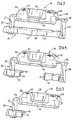
- FIG. 1 shows a partial view of a one-piece single cage with a spring element without a clamping body,
- FIG. 2 shows a partial view of the single cage with the clamping body inserted,
- FIG. 3 shows a view of a spring element,
- FIG. 4 shows a variant of the spring element,
- FIG. 5 shows a further variant of the spring element,
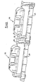
- FIG. 6 shows a double spring element,
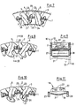
- FIG. 7 shows a partial view of the one-way clutch in the installed state,
- FIG. 8 shows a partial view of the one-way clutch in the non-installed state, the spring elements pressing on the clamping bodies,
- FIG. 9 shows a view along the line IX-IX according to FIG. 8,
- FIG. 10 shows a view corresponding to FIG. 8, the spring elements acting on the clamping bodies by tension,
- Figure 11 is a view of a spring element
- Figure 10,
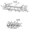
- Figure 12 shows another embodiment of a spring element and
- FIG. 13 shows a partial view of a one-way clutch with a spring element according to FIG. 12.
Ein Einzelkäfig (I) weist Borde (2,3) auf. Er ist mit Taschen (4) zur Aufnahme von Klemmkörpern (5) versehen. Die Taschen (4) sind von ebenen Randflächen (6,7) und stirnseitigen Rändern (8,9) begrenzt. Zwischen den stirnseitigen Rändern (8,9) besteht die größte axiale lichte Weite (L).A single cage (I) has shelves (2, 3). It is provided with pockets (4) for receiving sprags (5). The pockets (4) are delimited by flat edge surfaces (6,7) and front edges (8,9). The greatest axial clear width (L) exists between the front edges (8, 9).
Die stirnseitige Außenfläche des einen Bordes (2) und damit des Einzelkäfigs (1) liegt in einer radialen Ebene (10). Die andere stirnseitige Außenfläche des Einzelkäfigs (1) und damit des Bordes (3) liegt in einer radialen Ebene (11). Die stirnseitigen Ränder (8) der Taschen (4) verlaufen im Bereich der größten axialen lichten Weite (L) in einer radialen Ebene (12). Die stirnseitigen Ränder (9) liegen entsprechend an einer radialen Ebene (13). Beim Ausführungsbeispiel nach Figur 2 sind an den Rändern (8) geringfügig in die Taschen (4) vorstehende Anlageflächen (14) ausgeformt. Entsprechende Anlageflächen (15) sind an den Rändern (9) angeformt.The end face of the one flange (2) and thus the single cage (1) lies in a radial plane (10). The other end outer surface of the single cage (1) and thus the rim (3) lies in a radial plane (11). The front edges (8) of the pockets (4) run in a radial plane (12) in the area of the greatest axial clear width (L). The front edges (9) are accordingly on a radial plane (13). In the embodiment according to FIG. 2, contact surfaces (14) protruding slightly into the pockets (4) are formed on the edges (8). Corresponding contact surfaces (15) are formed on the edges (9).
Der Einzelkäfig (1) ist beispielsweise aus Flachmaterial gestanzt, gerollt und verschweißt.The single cage (1) is punched, rolled and welded from flat material, for example.
Zwischen den Taschen (4) verlaufen Stege (16). In diesen sind axiale Schlitze (17) vorgesehen, welche die Stege (16) so unterbrechen, daß sie beim Herstellungsschritt des Rollens eine entsprechende Biegung annehmen, d.h. der Käfig keine Polygonform annimmt.Crosspieces (16) run between the pockets (4). In these axial slots (17) are provided which interrupt the webs (16) so that they assume a corresponding bend during the manufacturing step of rolling, i.e. the cage has no polygon shape.
Jedem Klemmkörper (5) ist ein Anfederungselement (18) zugeordnet. Das Anfederungselement (18) ist aus federelastischem Flachmaterial gebogen. Es weist einen Haltebereich (19), einen an diesen anschließenden Federabschnitt (20) und einen Fortsatz (21) auf, der den Klemmkörper (5) im Einkoppelsinne mit der vom Federabschnitt (20) herrührenden Federkraft beaufschlagt.A spring element (18) is assigned to each clamping body (5). The spring element (18) is bent from resilient flat material. It has a holding area (19), a spring section (20) adjoining this and an extension (21) which acts on the clamping body (5) in the coupling direction with the spring force originating from the spring section (20).
Bei den Ausführungsbeispielen nach den Figuren 1 bis 11 ist der Haltebereich (19) von einer U-förmigen Lasche (22) gebildet, an der eine Zunge (23) ausgeformt ist. An einem Schenkel ist die Lasche (22) mit einer Abwinklung (24) versehen. Ein Schenkel der Lasche (22) ist über einen Steg (25) mit dem Federabschnitt (20) verbunden. Die Lasche (22) ist praktisch ebenso lang wie der Schlitz (17). Dadurch wird die axiale Fixierung des Anfederungselements (18) im Schlitz (17) gewährleistet. Um das Einführen der Lasche (22) in den Schlitz (17) zu erleichtern, ist diese mit Schrägen (26) versehen.In the exemplary embodiments according to FIGS. 1 to 11, the holding area (19) is formed by a U-shaped tab (22) on which a tongue (23) is formed. The tab (22) is provided with an angled portion (24) on one leg. One leg of the tab (22) is connected to the spring section (20) via a web (25). The tab (22) is practically as long as the slot (17). This ensures that the spring element (18) is axially fixed in the slot (17). In order to facilitate the insertion of the tab (22) into the slot (17), it is provided with bevels (26).
Das Anfederungselement (18) läßt sich auf einfache Weise an dem Einzelkäfig (1) festlegen. Es wird hierfür in den Käfig (I) axial eingeschoben und dann radial in den Schlitz (17) gesteckt, bis die Abwinklung (24) und der Steg (25) innenseitig am Steg (16) anliegen. Die Zunge (23) schnappt dabei außen auf den Steg (16). Eine gewisse Federkraft der Lasche (22) verbessert den Sitz. Die Anfederungselemente sind somit selbsthaltend am Einzelkäfig (1) auch dann festgelegt, wenn die Klemmkörper (5) noch nicht eingesetzt sind. Nach dem Einschnappen der Anfederungselemente (18) in die Schlitze (17) werden die Klemmkörper (5) in die Taschen (4) eingeschoben, wobei die Klemmkörper (5) dann so an den Fortsätzen (21) anliegen, daß sie im Einkopplungssinne von der Federkraft der Federabschnitte (20) beaufschlagt sind.The spring element (18) can be fixed in a simple manner on the single cage (1). For this purpose, it is inserted axially into the cage (I) and then inserted radially into the slot (17) until the bend (24) and the web (25) bear against the web (16) on the inside. The tongue (23) snaps onto the outside of the web (16). A certain spring force of the tab (22) improves the fit. The spring-loaded elements are thus fixed to the single cage (1) even when the clamping bodies (5) have not yet been inserted. After the spring elements (18) have snapped into the slots (17), the clamping bodies (5) are pushed into the pockets (4), the clamping bodies (5) then abutting the extensions (21) in such a way that they are coupled in from the Spring force of the spring sections (20) are applied.
Der Federabschnitt (20) ist von einer V-förmigen Biegung (27,28) gebildet. Die Biegung (27) liegt im Raum zwischen der radialen Ebene (10) und der radialen Ebene (12). Die Biegung (28) liegt im Raum zwischen der radialen Ebene (11) und der radialen Ebene (13). Damit liegen die Biegungen (27,28) neben den Klemmkörpem (5). Sie begrenzen also die mögliche axiale Länge der Klemmkörper nicht. Dies ist günstig, wenn die Klemmkörper (5) zur übertragung hoher Kräfte den Einzelkäfig (1) möglichst weitgehend ausfüllen sollen. Da die federwirksamen Biegungen (27,28) auch nicht zwischen benachbarten Klemmkörpem (5) angeordnet sind, ist auch in Umfangsrichtung gesehen eine weitestgehende Ausnutzung des Bauraums des Einzelkäfigs (1) möglich.The spring section (20) is formed by a V-shaped bend (27, 28). The bend (27) lies in the space between the radial plane (10) and the radial plane (12). The bend (28) lies in the space between the radial plane (11) and the radial plane (13). The bends (27, 28) thus lie next to the clamping bodies (5). So you do not limit the possible axial length of the clamping body. This is advantageous if the clamping bodies (5) are to fill the individual cage (1) as far as possible for the transmission of high forces. Since the spring-effective bends (27, 28) are also not arranged between adjacent clamping bodies (5), extensive use of the installation space of the individual cage (1) is also possible in the circumferential direction.
Beim Ausführungsbeispiel nach den Figuren 1 und 3 sind die Fortsätze (21) der Biegungen (27,28) von einem durchgehenden Quersteg (29) gebildet, der mit einer Rippe (30) versteift ist und mittig einen Vorsprung (31) zur Anlage an dem Klemmkörper (5) aufweist.In the exemplary embodiment according to FIGS. 1 and 3, the extensions (21) of the bends (27, 28) are formed by a continuous crosspiece (29) which is stiffened by a rib (30) and has a projection (31) in the center for bearing against it Has clamp body (5).
Beim Ausführungsbeispiel nach Figur 4 sind die Fortsätze (21) der Biegungen (27,28) getrennt. Beim Ausführungsbeispiel nach Figur 5 ist eine federwirksame Biegung nur einseitig vorgesehen.In the exemplary embodiment according to FIG. 4, the extensions (21) of the bends (27, 28) are separated. In the exemplary embodiment according to FIG. 5, a spring-effective bend is only provided on one side.
In Figur 6 ist ein Doppel-Anfederungselement dargestellt, das aus zwei Anfederungselementen (18) entsprechend Figur 3 besteht, die über eine Anbindung (32) miteinander verbunden sind. Dieses Doppel-Anfederungselement wird bei einem Einzelkäfig mit zwei Kränzen von Klemmkörpern verwendet. Entsprechend könnte auch ein Mehrfach-Anfederungselement aufgebaut sein.FIG. 6 shows a double spring element which consists of two spring elements (18) corresponding to FIG. 3, which are connected to one another via a connection (32). This double spring element is used in a single cage with two rings of sprags. A multiple spring element could also be constructed accordingly.
In Figur 7 ist der Einzelkäfig (1) im zwischen zwei Laufflächen (33,34) eingebauten Zustand dargestellt. Die Anfederungselemente (18) drücken mit ihren Fortsätzen (21) im Einkoppelsinne auf die Klemmkörper (5). Die Klemmkörper (5) sind Vollkörper ohne Schlitze, Bohrungen oder Lagerzapfen. Sie sind mit einer Verdickung (35) in der Tasche (4) gelagert. Der Fortsatz (21) drückt so auf den Klemmkörper (5), daß sich die Verdickung (35) an der in Umfangsrichtung gesehen gegenüberliegenden Randfläche (7) des Einzelkäfigs (1) abstützt.FIG. 7 shows the single cage (1) installed between two running surfaces (33, 34). The spring elements (18) press with their extensions (21) in the coupling direction on the clamping body (5). The clamping bodies (5) are solid bodies without slots, bores or bearing journals. They are stored in the pocket (4) with a thickening (35). The extension (21) presses on the clamping body (5) in such a way that the thickening (35) is supported on the peripheral surface (7) of the single cage (1), which is seen in the circumferential direction.
In Figur 8 und 9 ist der Einzelkäfig (1) im nicht zwischen Laufflächen eingebauten Zustand gezeigt. Mittels der auf die Klemmkörper (5) drückenden Anfederungselemente (18) sind die Klemmkörper (5) entsprechend verschwenkt und dadurch unverlierbar gehalten. Die Biegungen (27,28) liegen zwischen den radialen Ebenen (10,12 bzw. 11,13) (vgl. Figur 9) und dort zwischen den Klemmkörpern (5) (vgl. Figur 8).FIGS. 8 and 9 show the single cage (1) when it is not installed between the running surfaces. By means of the spring elements (18) pressing on the clamping bodies (5), the clamping bodies (5) are pivoted accordingly and are thus held captive. The bends (27, 28) lie between the radial planes (10, 12 and 11, 13) (see FIG. 9) and there between the clamping bodies (5) (see FIG. 8).
In den Figuren 10 und 11 ist ein Anfederungselement (18) gezeigt, das den ihm zugeordneten Klemmkörper (5) umgreift. Der Quersteg (29) wirkt hier auf Zug auf den Klemmkörper (5). Der Quersteg weist eine Durchbiegung (36) auf. An ihm ist mittig der Vorsprung (31) vorgesehen, der am Klemmkörper (5) anliegt. Es ist dadurch eine Selbstausrichtung des Klemmkörpers (5) erreicht.FIGS. 10 and 11 show a spring element (18) which engages around the clamping body (5) assigned to it. The crosspiece (29) acts here on the clamping body (5). The crossbar has a bend (36). The projection (31), which bears against the clamping body (5), is provided in the center of the latter. A self-alignment of the clamping body (5) is thereby achieved.
Bei den bisher beschriebenen Ausführungsbeispielen ist der Haltebereich (19) an dem Schlitz (17) befestigt. Weist der Einzelkäfig (1) die Schlitze (17) nicht auf, dann kann ein Anfederungselement (18) nach den Figuren 12 und 13 verwendet werden. Der Haltebereich (19) dieses Anfederungselements (18) bildet einen geschlossenen Rahmen (37), dessen Öffnung (38) im an dem Einzelkäfig (1) festgelegten Zustand mit der Tasche (4) fluchtet (vgl. Figur 13). Am Rahmen (37) sind beidseitig Doppelhaken (39,40) ausgebildet.In the exemplary embodiments described so far, the holding area (19) is fastened to the slot (17). If the single cage (1) does not have the slots (17), then a spring element (18) according to FIGS. 12 and 13 can be used. The holding area (19) of this spring element (18) forms a closed frame (37), the opening (38) of which is aligned with the pocket (4) in the state defined on the individual cage (1) (cf. FIG. 13). Double hooks (39, 40) are formed on both sides of the frame (37).
Das Anfederungselement (18) wird mit dem Doppelhaken (39,40) durch betreffende Tasche (4) gedrückt. Der Rahmen (37) liegt dann an der Innenseite der Stege (16) in der Umgebung der Tasche (4) an. Die Doppelhaken (39,40) übergreifen die Stege (16) oben. Das Einschnappen der flächigen Doppelhaken (39,40) ist durch die Federelastizität in den Bereichen (41) des Rahmens (37) möglich. Nach dem Einschnappen der Anfederungselemente (18) werden die Klemmkörper (5) in die Taschen (4) eingesetzt. Sie sind dann durch den Quersteg (29) unverlierbar gehalten.The spring element (18) is pressed with the double hook (39, 40) through the relevant pocket (4). The frame (37) then lies against the inside of the webs (16) in the vicinity of the pocket (4). The double hooks (39, 40) overlap the webs (16) at the top. Snap-in of the flat double hooks (39, 40) is possible due to the spring elasticity in the areas (41) of the frame (37). After the spring elements (18) have snapped in, the clamping bodies (5) are inserted into the pockets (4). You are then held captive by the crossbar (29).
Der Federabschnitt (27 bzw. 28) muß nicht von nur einer Biegung des Flachmaterials gebildet sein. Er kann auch mehrere Biegungen aufweisen, so daß er beispielsweise W-oder Z-förmige Gestalt hat.The spring section (27 or 28) need not be formed by only one bend in the flat material. It can also have several bends, so that it has, for example, a W or Z shape.
Es ist auch möglich, den Käfig (1) und die Anfederungselemente (18) gemeinsam einstückig aus Kunststoff herzustellen.It is also possible to manufacture the cage (1) and the resilient elements (18) together in one piece from plastic.
Claims (15)
Applications Claiming Priority (2)
| Application Number | Priority Date | Filing Date | Title |
|---|---|---|---|
| DE19873729632 DE3729632A1 (en) | 1987-09-04 | 1987-09-04 | FREE CLUTCH WITH CLAMP BODIES |
| DE3729632 | 1987-09-04 |
Publications (2)
| Publication Number | Publication Date |
|---|---|
| EP0306761A1 EP0306761A1 (en) | 1989-03-15 |
| EP0306761B1 true EP0306761B1 (en) | 1990-06-13 |
Family
ID=6335243
Family Applications (1)
| Application Number | Title | Priority Date | Filing Date |
|---|---|---|---|
| EP88113646A Expired - Lifetime EP0306761B1 (en) | 1987-09-04 | 1988-08-23 | Free-wheel clutch with wedging bodies |
Country Status (7)
| Country | Link |
|---|---|
| US (1) | US4867292A (en) |
| EP (1) | EP0306761B1 (en) |
| JP (1) | JPH0656187B2 (en) |
| AU (1) | AU608358B2 (en) |
| BR (1) | BR8804546A (en) |
| DE (2) | DE3729632A1 (en) |
| ES (1) | ES2015102B3 (en) |
Cited By (1)
| Publication number | Priority date | Publication date | Assignee | Title |
|---|---|---|---|---|
| DE10236154A1 (en) * | 2002-08-07 | 2004-02-19 | Ina-Schaeffler Kg | Override clutch has spring element with additional spring section charging a clamping body to reduce spring travel |
Families Citing this family (23)
| Publication number | Priority date | Publication date | Assignee | Title |
|---|---|---|---|---|
| US5064037A (en) * | 1990-03-01 | 1991-11-12 | Long Jr Thomas F | One-way acting sprag clutch with centrifugal disengagement from the outer race |
| US5146618A (en) * | 1990-05-24 | 1992-09-08 | Wenner Jeffrey W | Automotive radio support and conversion apparatus |
| US5070976A (en) * | 1990-12-27 | 1991-12-10 | Dana Corporation | Sprag retainer |
| US5101946A (en) * | 1991-09-03 | 1992-04-07 | General Motors Corporation | Cage phased roller clutch with improved roller shifting |
| DE4206438A1 (en) * | 1992-02-29 | 1993-09-02 | Scintilla Ag | HAND-DRIVEN, POWER-DRIVEN MACHINE |
| BG51056A3 (en) * | 1992-04-28 | 1993-01-15 | Dimitar B Filipov | Idle run clutch |
| DE9310178U1 (en) * | 1993-07-08 | 1993-09-02 | Schaeffler Waelzlager Kg | Sprag freewheel |
| US5383542A (en) * | 1993-12-27 | 1995-01-24 | Ford Motor Company | Overrunning clutch |
| US5607036A (en) * | 1995-03-03 | 1997-03-04 | Borg-Warner Automotive, Inc. | One-way clutch with stretchable spring member |
| JPH0942329A (en) * | 1995-07-24 | 1997-02-10 | Nsk Warner Kk | One-way clutch assembly |
| JP2003083366A (en) * | 2001-06-25 | 2003-03-19 | Nsk Warner Kk | One-way clutch device |
| DE10310225A1 (en) * | 2003-03-08 | 2004-09-16 | Ina-Schaeffler Kg | Overrunning clutch |
| US20090180721A1 (en) * | 2005-02-15 | 2009-07-16 | Stellario Barbera | Encoding Bearing Device and Rotating Machine |
| DE102005046896A1 (en) * | 2005-09-30 | 2007-04-05 | Schaeffler Kg | Free wheel clutch has inner ring and outer ring wherein throttle has sprags, and retainer with several cases is arranged between inner ring and outer ring |
| DE102005046800A1 (en) * | 2005-09-30 | 2007-04-05 | Schaeffler Kg | Freewheel cage ring for freewheel clutch, has ring shaped radially extending edge disks whereby edge disks are designed together with intermediate pieces as one-piece sheet metal component |
| FR2902699B1 (en) * | 2006-06-26 | 2010-10-22 | Skf Ab | SUSPENSION STOP DEVICE AND FORCE LEG. |
| FR2906587B1 (en) * | 2006-10-03 | 2009-07-10 | Skf Ab | TENDERING ROLLER DEVICE. |
| FR2906858B1 (en) * | 2006-10-04 | 2008-12-05 | Skf Ab | DEBRAYABLE PULLEY DEVICE. |
| FR2910129B1 (en) * | 2006-12-15 | 2009-07-10 | Skf Ab | INSTRUMENT BEARING BEARING DEVICE |
| FR2913081B1 (en) * | 2007-02-27 | 2009-05-15 | Skf Ab | DEBRAYABLE PULLEY DEVICE |
| DE102008030017B4 (en) * | 2008-06-24 | 2016-07-21 | Schaeffler Technologies AG & Co. KG | Metal cages for sprag clutches |
| US8186699B2 (en) | 2008-12-18 | 2012-05-29 | Steve Green | Wheelchair lever drive system |
| US9121495B2 (en) | 2013-03-15 | 2015-09-01 | Dayco Ip Holdings, Llc | Accessory drive decoupler |
Family Cites Families (23)
| Publication number | Priority date | Publication date | Assignee | Title |
|---|---|---|---|---|
| US2630896A (en) * | 1951-08-02 | 1953-03-10 | Adiel Y Dodge | One-way clutch |
| DE1142254B (en) * | 1951-12-24 | 1963-01-10 | Borg Warner | One-way clutch |
| US2824635A (en) * | 1951-12-24 | 1958-02-25 | Borg Warner | One-way engaging device |
| US2744598A (en) * | 1952-02-07 | 1956-05-08 | Borg Warner | One-way engaging mechanism |
| US2753027A (en) * | 1952-02-07 | 1956-07-03 | Borg Warner | One-way engaging mechanism |
| US2835363A (en) * | 1952-11-15 | 1958-05-20 | Nat Supply Co | Overrunning clutch |
| US3087588A (en) * | 1958-06-09 | 1963-04-30 | Gen Motors Corp | One-way engaging mechanism |
| US3031053A (en) * | 1959-03-06 | 1962-04-24 | Gen Motors Corp | One-way clutch |
| DE1915567B2 (en) * | 1969-03-27 | 1972-03-16 | Ringspann Albrecht Maurer Kg, 6380 Bad Homburg | FREE WHEEL COUPLING WITH CLAMPING PIECES |
| GB1314529A (en) * | 1969-06-06 | 1973-04-26 | Renold Ltd | Sprag clutches |
| DE6923286U (en) * | 1969-06-11 | 1970-11-12 | Schaeffler Ohg Industriewerk | CLAMPING ROLLERS - FREE WHEEL |
| FR2147416A5 (en) * | 1971-07-27 | 1973-03-09 | Ferodo Sa | |
| SE7407449L (en) * | 1973-07-20 | 1975-01-21 | Ciba Geigy Ag | |
| US3863742A (en) * | 1973-08-08 | 1975-02-04 | Torrington Co | Retainer for overrunning clutch |
| JPS51117956U (en) * | 1975-03-18 | 1976-09-24 | ||
| DE2714046C2 (en) * | 1977-03-30 | 1985-12-05 | Stieber Division Der Borg-Warner Gmbh, 6900 Heidelberg | Sprag overrunning clutch with a cage for receiving and holding the sprags |
| FR2456258A1 (en) * | 1979-05-10 | 1980-12-05 | Skf Cie Applic Mecanique | FREE SIDE RECALL WHEEL |
| JPS5612138U (en) * | 1980-05-27 | 1981-02-02 | ||
| DE3023687A1 (en) * | 1980-06-25 | 1982-01-14 | Industriewerk Schaeffler Ohg, 8522 Herzogenaurach | ONE-PIECE SHEET CAGE FOR A CLAMP ROLLER FREEWHEEL |
| JPS5966033U (en) * | 1982-10-26 | 1984-05-02 | 光洋精工株式会社 | On the other hand, clutch |
| JPS6026337U (en) * | 1983-07-28 | 1985-02-22 | 光洋精工株式会社 | sprag clutch |
| US4712661A (en) * | 1986-05-16 | 1987-12-15 | General Motors Corporation | Overrunning clutch cage |
| FR2601735B1 (en) * | 1986-07-16 | 1990-08-24 | Skf France | FREE WHEEL DEVICE WITH SELF-CENTERING CAMS WITH BEARINGS |
-
1987
- 1987-09-04 DE DE19873729632 patent/DE3729632A1/en not_active Withdrawn
-
1988
- 1988-08-19 US US07/234,397 patent/US4867292A/en not_active Expired - Lifetime
- 1988-08-23 DE DE8888113646T patent/DE3860226D1/en not_active Expired - Lifetime
- 1988-08-23 EP EP88113646A patent/EP0306761B1/en not_active Expired - Lifetime
- 1988-08-23 ES ES88113646T patent/ES2015102B3/en not_active Expired - Lifetime
- 1988-09-02 BR BR8804546A patent/BR8804546A/en not_active IP Right Cessation
- 1988-09-02 JP JP63218625A patent/JPH0656187B2/en not_active Expired - Lifetime
- 1988-09-02 AU AU21849/88A patent/AU608358B2/en not_active Ceased
Cited By (1)
| Publication number | Priority date | Publication date | Assignee | Title |
|---|---|---|---|---|
| DE10236154A1 (en) * | 2002-08-07 | 2004-02-19 | Ina-Schaeffler Kg | Override clutch has spring element with additional spring section charging a clamping body to reduce spring travel |
Also Published As
| Publication number | Publication date |
|---|---|
| EP0306761A1 (en) | 1989-03-15 |
| AU608358B2 (en) | 1991-03-28 |
| DE3729632A1 (en) | 1989-03-16 |
| DE3860226D1 (en) | 1990-07-19 |
| JPH0656187B2 (en) | 1994-07-27 |
| JPS6474330A (en) | 1989-03-20 |
| ES2015102B3 (en) | 1990-08-01 |
| AU2184988A (en) | 1989-03-09 |
| US4867292A (en) | 1989-09-19 |
| BR8804546A (en) | 1989-04-11 |
Similar Documents
| Publication | Publication Date | Title |
|---|---|---|
| EP0306761B1 (en) | Free-wheel clutch with wedging bodies | |
| DE2438007C2 (en) | Cage for holding the rollers of a pinch roller overrunning clutch | |
| DE3320063C2 (en) | ||
| DE1908137A1 (en) | Cage for overrunning clutch with spring insert | |
| EP0950820B1 (en) | Retaining ring | |
| DE102005056220A1 (en) | Overrunning clutch | |
| DE3023687A1 (en) | ONE-PIECE SHEET CAGE FOR A CLAMP ROLLER FREEWHEEL | |
| DE4303855C1 (en) | Compound radial-axial plain bearing | |
| DE102010007706A1 (en) | Bearing combination for radial and axial support, in particular for a loose or intermediate gear in a transmission | |
| DE19640608B4 (en) | One-way clutch and method for its production | |
| DE8616605U1 (en) | Sprag freewheel | |
| EP1065396B1 (en) | Sheet metal cage for roller bearing | |
| DE4140277A1 (en) | ASSEMBLED RADIAL-AXIAL SLIDING BEARING AND METHOD FOR THE PRODUCTION THEREOF | |
| DE102018124068A1 (en) | drive belts | |
| DE2714046A1 (en) | CLAMPING BODY FREE-WHEEL COUPLING WITH A CAGE TO RECEIVE AND HOLD THE CLAMPING BODIES | |
| EP0575585B1 (en) | Linear roller-bearing raceway with cage | |
| DE3527423C2 (en) | ||
| DE4220585A1 (en) | Roller bearing cage, esp. for cylindrical or pin bearings - has detachable connecting elements fitting into recesses in free ends of cage, near slit surfaces on cage periphery | |
| DE3933667C1 (en) | Combined radial and axial bearing bush - includes split bearing shells and two detachable thrust ring couplings | |
| WO2020164652A1 (en) | Clamping roller freewheel | |
| DE102006061378B3 (en) | Conveyor clamp for paired antifriction bearing, has bearing inner ring and bearing outer ring and rolling element arranged between inner and outer rings | |
| DE4142801A1 (en) | Needle bearing cage for machine assembly - has linking ends of cage with self locating claws with automatic alignment | |
| DE3223994C2 (en) | Axial locking element | |
| DE3514018A1 (en) | HOLDING RING | |
| DE102017116356A1 (en) | roll bearings |
Legal Events
| Date | Code | Title | Description |
|---|---|---|---|
| PUAI | Public reference made under article 153(3) epc to a published international application that has entered the european phase |
Free format text: ORIGINAL CODE: 0009012 |
|
| 17P | Request for examination filed |
Effective date: 19880826 |
|
| AK | Designated contracting states |
Kind code of ref document: A1 Designated state(s): DE ES FR GB IT |
|
| 17Q | First examination report despatched |
Effective date: 19890825 |
|
| ITF | It: translation for a ep patent filed |
Owner name: DE DOMINICIS & MAYER S.R.L. |
|
| GRAA | (expected) grant |
Free format text: ORIGINAL CODE: 0009210 |
|
| AK | Designated contracting states |
Kind code of ref document: B1 Designated state(s): DE ES FR GB IT |
|
| GBT | Gb: translation of ep patent filed (gb section 77(6)(a)/1977) | ||
| REF | Corresponds to: |
Ref document number: 3860226 Country of ref document: DE Date of ref document: 19900719 |
|
| ET | Fr: translation filed | ||
| PLBE | No opposition filed within time limit |
Free format text: ORIGINAL CODE: 0009261 |
|
| STAA | Information on the status of an ep patent application or granted ep patent |
Free format text: STATUS: NO OPPOSITION FILED WITHIN TIME LIMIT |
|
| 26N | No opposition filed | ||
| ITTA | It: last paid annual fee | ||
| PGFP | Annual fee paid to national office [announced via postgrant information from national office to epo] |
Ref country code: GB Payment date: 19940725 Year of fee payment: 7 |
|
| PGFP | Annual fee paid to national office [announced via postgrant information from national office to epo] |
Ref country code: FR Payment date: 19940802 Year of fee payment: 7 |
|
| PGFP | Annual fee paid to national office [announced via postgrant information from national office to epo] |
Ref country code: ES Payment date: 19940816 Year of fee payment: 7 |
|
| PG25 | Lapsed in a contracting state [announced via postgrant information from national office to epo] |
Ref country code: GB Effective date: 19950823 |
|
| PG25 | Lapsed in a contracting state [announced via postgrant information from national office to epo] |
Ref country code: ES Free format text: LAPSE BECAUSE OF THE APPLICANT RENOUNCES Effective date: 19950824 |
|
| GBPC | Gb: european patent ceased through non-payment of renewal fee |
Effective date: 19950823 |
|
| PG25 | Lapsed in a contracting state [announced via postgrant information from national office to epo] |
Ref country code: FR Effective date: 19960430 |
|
| REG | Reference to a national code |
Ref country code: FR Ref legal event code: ST |
|
| REG | Reference to a national code |
Ref country code: ES Ref legal event code: FD2A Effective date: 19991007 |
|
| PG25 | Lapsed in a contracting state [announced via postgrant information from national office to epo] |
Ref country code: IT Free format text: LAPSE BECAUSE OF NON-PAYMENT OF DUE FEES;WARNING: LAPSES OF ITALIAN PATENTS WITH EFFECTIVE DATE BEFORE 2007 MAY HAVE OCCURRED AT ANY TIME BEFORE 2007. THE CORRECT EFFECTIVE DATE MAY BE DIFFERENT FROM THE ONE RECORDED. Effective date: 20050823 |
|
| PGFP | Annual fee paid to national office [announced via postgrant information from national office to epo] |
Ref country code: DE Payment date: 20070816 Year of fee payment: 20 |