EP0306178A2 - Capteur d'accélération - Google Patents
Capteur d'accélération Download PDFInfo
- Publication number
- EP0306178A2 EP0306178A2 EP88307622A EP88307622A EP0306178A2 EP 0306178 A2 EP0306178 A2 EP 0306178A2 EP 88307622 A EP88307622 A EP 88307622A EP 88307622 A EP88307622 A EP 88307622A EP 0306178 A2 EP0306178 A2 EP 0306178A2
- Authority
- EP
- European Patent Office
- Prior art keywords
- acceleration sensor
- set forth
- acceleration
- magnetic
- base
- Prior art date
- Legal status (The legal status is an assumption and is not a legal conclusion. Google has not performed a legal analysis and makes no representation as to the accuracy of the status listed.)
- Ceased
Links
Images


Classifications
-
- G—PHYSICS
- G01—MEASURING; TESTING
- G01P—MEASURING LINEAR OR ANGULAR SPEED, ACCELERATION, DECELERATION, OR SHOCK; INDICATING PRESENCE, ABSENCE, OR DIRECTION, OF MOVEMENT
- G01P3/00—Measuring linear or angular speed; Measuring differences of linear or angular speeds
- G01P3/42—Devices characterised by the use of electric or magnetic means
- G01P3/44—Devices characterised by the use of electric or magnetic means for measuring angular speed
- G01P3/48—Devices characterised by the use of electric or magnetic means for measuring angular speed by measuring frequency of generated current or voltage
- G01P3/481—Devices characterised by the use of electric or magnetic means for measuring angular speed by measuring frequency of generated current or voltage of pulse signals
- G01P3/487—Devices characterised by the use of electric or magnetic means for measuring angular speed by measuring frequency of generated current or voltage of pulse signals delivered by rotating magnets
-
- G—PHYSICS
- G01—MEASURING; TESTING
- G01P—MEASURING LINEAR OR ANGULAR SPEED, ACCELERATION, DECELERATION, OR SHOCK; INDICATING PRESENCE, ABSENCE, OR DIRECTION, OF MOVEMENT
- G01P15/00—Measuring acceleration; Measuring deceleration; Measuring shock, i.e. sudden change of acceleration
- G01P15/02—Measuring acceleration; Measuring deceleration; Measuring shock, i.e. sudden change of acceleration by making use of inertia forces using solid seismic masses
- G01P15/08—Measuring acceleration; Measuring deceleration; Measuring shock, i.e. sudden change of acceleration by making use of inertia forces using solid seismic masses with conversion into electric or magnetic values
- G01P15/105—Measuring acceleration; Measuring deceleration; Measuring shock, i.e. sudden change of acceleration by making use of inertia forces using solid seismic masses with conversion into electric or magnetic values by magnetically sensitive devices
-
- G—PHYSICS
- G01—MEASURING; TESTING
- G01P—MEASURING LINEAR OR ANGULAR SPEED, ACCELERATION, DECELERATION, OR SHOCK; INDICATING PRESENCE, ABSENCE, OR DIRECTION, OF MOVEMENT
- G01P15/00—Measuring acceleration; Measuring deceleration; Measuring shock, i.e. sudden change of acceleration
- G01P15/02—Measuring acceleration; Measuring deceleration; Measuring shock, i.e. sudden change of acceleration by making use of inertia forces using solid seismic masses
- G01P15/08—Measuring acceleration; Measuring deceleration; Measuring shock, i.e. sudden change of acceleration by making use of inertia forces using solid seismic masses with conversion into electric or magnetic values
- G01P15/0802—Details
-
- G—PHYSICS
- G01—MEASURING; TESTING
- G01P—MEASURING LINEAR OR ANGULAR SPEED, ACCELERATION, DECELERATION, OR SHOCK; INDICATING PRESENCE, ABSENCE, OR DIRECTION, OF MOVEMENT
- G01P15/00—Measuring acceleration; Measuring deceleration; Measuring shock, i.e. sudden change of acceleration
- G01P15/02—Measuring acceleration; Measuring deceleration; Measuring shock, i.e. sudden change of acceleration by making use of inertia forces using solid seismic masses
- G01P15/08—Measuring acceleration; Measuring deceleration; Measuring shock, i.e. sudden change of acceleration by making use of inertia forces using solid seismic masses with conversion into electric or magnetic values
- G01P2015/0805—Measuring acceleration; Measuring deceleration; Measuring shock, i.e. sudden change of acceleration by making use of inertia forces using solid seismic masses with conversion into electric or magnetic values being provided with a particular type of spring-mass-system for defining the displacement of a seismic mass due to an external acceleration
- G01P2015/0808—Measuring acceleration; Measuring deceleration; Measuring shock, i.e. sudden change of acceleration by making use of inertia forces using solid seismic masses with conversion into electric or magnetic values being provided with a particular type of spring-mass-system for defining the displacement of a seismic mass due to an external acceleration for defining in-plane movement of the mass, i.e. movement of the mass in the plane of the substrate
- G01P2015/0811—Measuring acceleration; Measuring deceleration; Measuring shock, i.e. sudden change of acceleration by making use of inertia forces using solid seismic masses with conversion into electric or magnetic values being provided with a particular type of spring-mass-system for defining the displacement of a seismic mass due to an external acceleration for defining in-plane movement of the mass, i.e. movement of the mass in the plane of the substrate for one single degree of freedom of movement of the mass
- G01P2015/0817—Measuring acceleration; Measuring deceleration; Measuring shock, i.e. sudden change of acceleration by making use of inertia forces using solid seismic masses with conversion into electric or magnetic values being provided with a particular type of spring-mass-system for defining the displacement of a seismic mass due to an external acceleration for defining in-plane movement of the mass, i.e. movement of the mass in the plane of the substrate for one single degree of freedom of movement of the mass for pivoting movement of the mass, e.g. in-plane pendulum
-
- Y—GENERAL TAGGING OF NEW TECHNOLOGICAL DEVELOPMENTS; GENERAL TAGGING OF CROSS-SECTIONAL TECHNOLOGIES SPANNING OVER SEVERAL SECTIONS OF THE IPC; TECHNICAL SUBJECTS COVERED BY FORMER USPC CROSS-REFERENCE ART COLLECTIONS [XRACs] AND DIGESTS
- Y10—TECHNICAL SUBJECTS COVERED BY FORMER USPC
- Y10S—TECHNICAL SUBJECTS COVERED BY FORMER USPC CROSS-REFERENCE ART COLLECTIONS [XRACs] AND DIGESTS
- Y10S73/00—Measuring and testing
- Y10S73/03—Hall effect
Definitions
- This invention relates to an acceleration sensor.
- An acceleration sensor having a beam which is bendable or deformable according to an acceleration exerted thereon is known.
- One of such known sensors comprises a cantilever beam having one end fixed to a base, a weight rigidly secured, to the other end of the beam, an electrode attached to the base at the same level as the weight, and another electrode fixed on the base.
- the weight is moved and the beam is bent in accordance with an acceleration exerted on the weight. Therefore, the distance, i.e., the static electrical capacity between the two electrodes, is changed and, therefore, a value of acceleration according to the change can be detected.
- a direct current electrical resistance between the two electrodes can be measured to determine a value of acceleration.
- This type of known acceleration sensor can only be used when the direction of acceleration is constant and when the capacity change is relatively large, since it is relatively difficult to detect the change in the static electrical capacity between the two electrodes.
- Another known acceleration sensor also includes a cantilever beam bendable in accordance with an acceleration and a strain gauge mounted on the beam, so that a strain of the cantilever, i.e., a change in the electrical resistance of the strain gauge, corresponding to a value of acceleration exerted on a weight attached to a free end of the cantilever is detected.
- the cantilever may be made of a silicon substrate.
- a semiconductor acceleration sensor is used to detect a value of acceleration on the basis of the change in this resistance.
- the cantilever beam possibly may be bent in other directions or torsioned according to the direction of an acceleration. In this case, an accurate detection of a value of acceleration in a particular direction, cannot be obtained.
- An embodiment of the present invention may provide an acceleration sensor having a simple construction including a combination of one or more magnetoresistive sensors and a permanent magnet, and capable of stably detecting a value of an acceleration.
- An embodiment of the present invention may also provide an acceleration sensor capable of overcoming the disadvantages mentioned above with reference to the prior art.
- an acceleration sensor comprising: a base; a deformable member having at least one first portion rigidly secured to said base and a second portion separate from said first portion, said member being made of a material such that said second portion is moved by a certain distance from an initial position thereof when said member is deformed according to an acceleration exerted thereon, and returns to said initial position when an acceleration is not exerted thereon; one of a permanent magnet and a magnetic sensor comprising a magnetoresistive sensing element being attached to said deformable member at said second portion; the other of said permanent magnet and magnetic sensor being stationarily mounted on said base opposite to said one of a permanent magnet and a magnetic sensor and substantially on a line of direction along which said one of a permanent magnet and a magnetic sensor is moved; and an electrical circuit for detecting the acceleration according to an output from said magnetic sensor.
- an acceleration sensor comprising: a base; a deformable member having at least one first portion rigidly secured to said base and a second portion separate from said first portion, said member being made of a material such that said second portion is moved by a certain distance from an initial position thereof when said member is deformed according to an acceleration exerted thereon and returned to said initial position when an acceleration is not exerted thereon; a permanent magnet attached to said deformable member at said second portion; at least a pair of magnetic sensors, each comprising a magnetoresistive sensing element, station severelyarily mounted on said base opposite to said magnet and arranged substantially symmetrically with respect to said magnet, when an acceleration is not exerted thereon; and an electrical circuit for detecting the acceleration according to outputs from said magnetic sensors.
- the deformable member may be advantageously constituted by a cantilever having a first end rigidly secured to said base and a second or free end to which said permanent magnet is attached.
- the magnetic sensor is preferably a barber-pole type magnetoresistive sensing element.
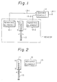
- an acceleration sensor of this invention essentially includes a beam 10 which is bent according to an acceleration exerted thereon, a permanent magnet 11 having N and S poles as shown, a pair of barber-pole type magnetoresistive sensing elements 12-1 and 12-2, output signal lines 13-1 and 13-2 of the elements 12-1 and 12-2, respectively, an adding circuit 14, and an output signal terminal 14-1.
- a cantilever beam 10 bendable by an acceleration has one end rigidly secured to the base and the other end to which a permanent magnet 11 is attached.
- a pair of barber-pole type magnetoresistive sensing elements 12-1 and 12-2 are arranged at the respective sides of the permanent magnet 11 and symmetrically with respect to the beam 10.
- the output signals of these barber-pole elements 12-1 and 12-2 are input through the output signal lines 13-1 and 13-2 to an adding circuit 14 in which the outputs are added in the reverse pole, so that an acceleration is determined in accordance with the output from the adding circuit 14.
- An operation to determine a value of acceleration can be also carried out in a same manner as above, even if a magnetoresistive element 12 is attached on one end of a beam 10 and a pair of magnets 11 are stationarily arranged at the respective sides of the element 12 and symmetrically with respect to the beam 10, or even if a magnetoresistive element 12 is attached on a middle portion of a bendable beam supported by the respective ends thereof.
- the magnetoresistive elements 12-1 and 12-2 detect the distance independently.
- the outputs of the elements 12-1 and 12-2 are transmitted via the signal lines 13-1 and 13-2, respectively, to the adding circuit 14, in which the values are added in reverse polarity to each other.
- an output obtained is at the adding circuit 14 which is twice the output of each of the respective elements 12-1 and 12-2.
- the magnetoresistive elements 12-1 and 12-2 are readily affected by a disturbance of a magnetic field, such as a geomagnetism. But, according to this arrangement, such a disturbance is counterbalanced and the output signals are enhanced twice in the adding circuit 14, so that a highly sensitive and practical acceleration sensor can be obtained by using barber-pole magnetoresistive sensing elements, which provide a straight output with respect to a magnetic field and can be arranged at preferred positions, since they do not need a bias magnetic field, as will be mentioned later.
- a coil spring 15 is used instead of the beam 10 and the magnet 11 is attached to a top end of the coil spring 15.
- the distance between the magnet 11 and a magnetoresistive sensing element 12 is changed by the coil spring 15 in the direction shown by an arrow 16, so that an acceleration can be detected in the same manner as in the previous embodiments shown in Figs. 1 and 2.
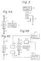
- Figure 4A shows an embodiment including another beam 17 supported by the respective ends thereof.
- the respective ends of the beam 17 are fixedly connected to the base and a magnet 11 is mounted on a middle portion of the beam 17 so as to face a single magnetoresistive sensing element 12.
- a magnet 11 is mounted on a middle portion of the beam 17 so as to face a single magnetoresistive sensing element 12.
- Fig. 4B respective ends of a beam 17 are fixedly connected to the base and two pairs of magnetoresistive sensing elements 12-1, 12-2, 12-3, and 13-4 are arranged at respective sides of the magnet 11 on respective lines perpendicular to each other.
- a value of acceleration can be obtained as changes in gaps between the magnet 11 and the elements 12-1 and 12-2.
- an accurate value of acceleration cannot be obtained from an output of the adding circuit 14-1 in which the outputs of the elements 12-1 and 12-2 are only added.
- this embodiment provides another pair of magnetoresistive elements 12-3 and 12-4 so that another output is obtained in the adding circuit 14-2, in which the both outputs are added as vectors.
- a beam 17 may be a cantilever or a beam supported by the respective ends thereof and may have a circular or rectangular cross-section.
- a coil spring 18 is fixedly connected to the base by respective ends thereof and a magnet 11 is mounted on a middle portion of the coil spring 18.
- FIG. 5 shows in detail an embodiment of an acceleration sensor indicated by a dotted line in Fig. 1, in which a silicon substrate is used.
- This acceleration sensor comprises a silicon wafer 20 having an opening 21 provided therein, a beam 10, a permanent magnet 11, a pair of magnetoresistive sensing elements 32-1 and 32-2 used as transducers, and conductive pads 22-1 to 22-4 integrally formed with these elements 32-1 and 32-2 on the silicon wafer 20 for connecting these elements to an adding circuit (not shown).
- the beam 10 may be made of phosphorus bronze
- the permanent magnet 11 may be made of samarium cobalt having Br: 7000 gauss and Hc: 7000 oersted .
- the silicon substrate 20 is provided at the one side of the opening 21 with a recess 23 to which the beam 10 is fixedly inserted.
- the beam 10 has a larger thickness in the transverse direction than in the vertical direction in the drawing.
- the opening 21 and recess 23 can be accurately formed by, for example, an etching process.
- the beam 10 can be bent in either direction toward the element 32-1 or 32-2 due to an acceleration exerted thereon in the horizontal direction.
- Each of the elements 32-1 and 32-2 may be constructed as a bridge consisting of four resistors R and formed on the silicon substrate 20, as shown in Fig. 6.
- each of the elements 32-1 and 32-2 may be constructed in the shape of a barber-pole. In this case, a bias magnetic field is no longer necessary and a preferred output, i.e., a straight output with respect to the external magnetic field, can be obtained.
- a preferred output i.e., a straight output with respect to the external magnetic field
- Both the beam 10 and magnet 11 shown in Fig. 5 may be made integrally as a single piece form, for example, a semirigid magnetic material.
- FIGS 7A and 7B are diagrams showing outputs of the acceleration sensors.
- a wave curve (I) in Fig. 7A shows an output of a known acceleration sensor which is commercially available.
- a wave curve (II) in Fig. 7A shows an output of an acceleration sensor according to the embodiment of this invention as shown in Fig. 5.
- the output voltage changes by about 1 volt with respect to a value of acceleration of +1G or -1G. It has been confirmed that the relationship between the value of acceleration G and the output voltage V has a substantially linear characteristic, as shown in Fig. 7B.
- Figure 8 is a cross-sectional view taken along a vertical plane for connecting the magnetoresistive sensing elements 12-1 and 12-2 in Fig. 1, but showing another embodiment thereof.
- a silicon substrate 20 is provided with a recess 24 and a vertical beam 25 is formed integrally with this silicon substrate. 20.
- Magnetoresistive sensing elements 12-1 and 12-2 and a magnet 11 are arranged to be in a same horizontal plane. Inner walls of the recess 24 serve as stoppers, when or if the beam 25 is suddenly bent by abrupt shocks.
- Figure 9 is a cross-sectional view showing still another embodiment.
- a vertical beam 25 extends opposite to the embodiment of Fig. 8.
- the beam 25 may be made of silicon or any other material.
- the upper and lower silicon substrates are provided with projections and holes as shown at 26-1, 26-2, ...., and these projections are fitted into the holes to obtain a highly accurate acceleration sensor.
- the embodiment of Fig. 9 is advantageously applied to constitute an acceleration sensor as shown in Fig. 4A having two pairs of magnetoresistive sensing elements 12-1, 12-2, 12-3, and 12-4.
- FIG 10 is an exploded perspective view illustrating an embodiment of an acceleration sensor according to the present invention.
- a cap 27 and a base 28 cooperatively constituting a hermetic shield case are made of a magnetic material such as silicon steel, and the surfaces thereof are plated with nickel.
- the cap 27 has a sealing inlet 27-1 and the base 28 has external terminals 29-1 to 29-6 and other terminals 29-7 and 29-8, insulated from and fixed to this base 28.
- the cap 27 is put on the base 28 and then the periphery of the cap 27 and base 28 are hermetically sealed together by, for example, welding, to form a magnetic shield case. Then, oil is filled into the case through the inlet 27-1 to prevent undesirable vibration and the inlet 27-1 is sealingly closed.
- An acceleration sensor according to the present invention is thus obtained, and such a sensor can be mounted on a printed circuit board.
- the acceleration sensor shown in Fig. 10 has substantially the same construction as an embodiment shown in Fig. 5.
- a silicon substrate 30 has an opening 31 formed by an anisotropic etching and a cantilever beam 10 fixedly inserted into a recess 33.
- a permanent magnet 11 is attached to the beam 10 at one end thereof.
- a pair of barber-pole type magnetoresistive sensing elements 12-1 and 12-2 are arranged on the frame surfaces of the silicon substrate 30 which is fixed on the base 28 by an appropriate adhesive.
- the magnetoresistive sensing elements 12-1 and 12-2 have connecting pads 32-1 to 32-6, numbered 1 to 6, which are connected to the external terminals 29-1 to 29-6, respectively, via aluminum wires (as shown in Fig. 10) by a wire bonding process.
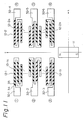
- Each of the barber-pole type elements 12-1 and 12-2 is formed in practice as a pattern shown in Fig. 11, including a winding or zig-zag pattern of a magnetic thin film 34 made of, for example, permalloy (Ni-Fe alloy), and a plurality of conductive patterns 35 attached thereon so as to incline thereto by, for example, 45°.
- the connecting pads 32-1 to 32-6 are formed as parts of these magnetic thin film patterns 34 having longitudinally elongated portions parallel to the x-axis and perpendicular to the z-axis.
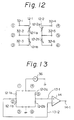
- Each of the elements 12-1 and 12-2 includes resistive portions 12-1a and 12-1b, and 12-2a and 12-2b connected to each other in series and, thus, the barber-pole type patterns are connected to each other to form a bridge in such a manner that the voltage changes of the magnetoresistive sensing elements 12-1 and 12-2 according to the external magnetic field are output in a reverse polarity to each other and the voltage changes of the resistive portions 12-1a and 12-1b (and 12-2a and 12-2b) are output in a reverse polarity to each other.
- Figure 12 shows an equivalent circuit of the magnetoresistive sensing elements 12-1 (12-1a and 12-1b) and 12-2 (12-2a and 12-2b), in which the connecting pads 32-1 to 32-6 are used as terminals.
- these sensing elements are connected at the outside of the hermetic shield case to form a bridge as shown in Fig. 13, in which a D.C. power 36 is connected to the bridge to supply a constant current to the respective sensing elements, so that the output signals thereof are input to the adding circuit 14 having an output terminal 14-1 as shown in Fig. 1.
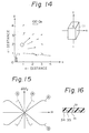
- Figure 14 shows a magnetic field distribution and an orientation of the magnet 11, in which a simulated distribution is represented as shown on a plane of x and z-axes under a condition that a central point of the magnet 11 is located at an intersection of the x and z-axes.
- the magnet 11 made of samarium cobalt has Br: 7000 gauss and Hc: 7000 oersted , as mentioned above.
- each arrow represents the orientation and strength of the magnetic field.
- the positions of the elements 12-1 and 12-2 with respect to the magnet 11 are determined, and thus, using this magnet 11 itself, a predetermined initial magnetism can be automatically given to each of the elements 12-1 and 12-2 without any particular bias magnetic field means.
- the magnetoresistive sensing element 12-1 (or 12-2) having a thin film magnetic pattern 34 parallel to the x-axis is located at a point indicated by o, and an initial magnetism of 150 oersted can be given to the thin film magnetic pattern 34.
- the initial magnetism is given in the longitudinal direction (x-axis) of the thin film magnetic pattern 34 as shown by arrows M in Fig. 16 and angled by 45° to the direction of current shown by arrows m between the conductive patterns 35.
- the output characteristics (i.e., changes of voltage ⁇ V/V with respect to the external magnetic field H by the magnet 11) of the magnetoresistive sensing elements 12-1 and 12-2 are represented as solid lines (A) and (B) in Fig. 15, from which it is clearly understood that the range of measurement can be significantly increased when compared with the output characteristics represented by dotted lines (a) and (b) when such an initial magnetism is not given.
- Figure 17 shows a process for making a sensor.
- a silicon wafer 37 having a face orientation of 100, as illustrated in (A), is formed with a plurality of holes 31 and cut into a plurality of rectangular shaped silicon substrates 30.
- the surface of the silicon wafer 37 is coated with an oxide film 38 by heat oxidation as shown in (B) and then coated with a resist, which is then exposed with a light beam and developed to form a resist film 40 having a substantially rectangular opening 39 as shown in (C) and (C′).
- the oxide film 38 on the exposed opening 39 is then removed and the resist film 40 is also removed, to obtain a masking pattern 38a of the oxide film 38 having an opening 38b as shown in (D) and (D′).
- a through opening 31 having a recess 33 is formed by anisotropically etching the portion of opening 38b as shown in (E) and (E′).
- the etching depth is 60 to 80 ⁇ m/hour and, therefore, such an opening 31 can be formed in about four hours, assuming that the thickness of the silicon wafer 37 is 280 ⁇ m.
- magnetoresistive sensing elements 12-1 and 12-2 are formed on the frame portions thereof as shown in (F).
- These elements 12-1 and 12-2 are formed as follows. As shown in (F), magnetic layers 41, film layers 42 consisting of Ta.Mo or the like, and conductive layers 43 are formed by evaporation on the oxide film of the silicon wafer 37. Then, thin film magnetic patterns 34 of the magnetic layers 41 and conductive patterns 35 of the conductive layers 43 are formed, respectively, by a patterning, such as etching.
- the surface of the wafer 37 is coated with a protective layer 44 consisting of Si3N4 or the like.
- the silicon wafer 37 is cut along a dotted line as shown in (F) to obtain a plurality of rectangular shaped silicon substrates 30.
- Magnetoresistive sensing elements 12-1 and 12-2 may be made by another method separately from such a silicon wafer 37 and then rigidly adhered to the frame surfaces of the silicon wafer 37.
- Figure 18 is an exploded perspective view, similar to Fig. 10, but illustrating another embodiment of acceleration sensor according to the present invention.
- the cap 27 having a sealing inlet 27-1 and the base 28 having terminals 29-1 to 29-8 are the same as those of the embodiment shown in Fig. 10.
- a cantilever beam 10 made of, for example, phosphoric bronze, has one end to which a permanent magnet 11 is attached and the other end which is fixedly supported on one end of the support member 30a.
- a pair of barber-pole type magnetoresistive sensing elements 12-1 and 12-2 are arranged on the support members 30a and 30b, respectively, which are fixed on the base 28 by an appropriate adhesive and serve as stoppers when the beam 10 is bent by abrupt shocks.
- These elements 12-1 and 12-2 have connecting pads 32-1 to 32-6, numbered 1 to 6 , which are connected to the external terminals 29-1 to 29-6, respectively, via aluminum bonding wires.
- Figure 19 is a view similar to Fig. 11, but illustrating another pattern of the barber-pole type magnetoresistive sensing elements 12-1 and 12-2, each of which consists of two winding or zig-zag patterns 12-1a and 12-1b (and 12-2a and 12-2b) made of magnetic thin films 34 of permalloy (Ni-Fe alloy) and extending substantially in parallel to each other.
- These patterns 12-1a and 12-1b have one ends defining input terminal pads 40-1 and 40-2 and other ends connected to each other to form an output terminal pad 40-3.
- the patterns 12-2a and 12-2b have input terminal pads 40-4 and 40-5 and an output terminal pad 40-6.
- a plurality of conductive stripe patterns 35 are formed on each of the magnetic thin films 34 so as to incline thereto by, for example, 45°.
- the conductive patterns 35 on the films 12-1a and 12-1b are, however, inclined in the opposite directions to each other, so that a bias current i1 flowing through the conductive pattern 35 on the film 12-1a and a bias current i2 flowing through the conductive pattern 35 on the film 12-1b are angled by, for example, 90°, as shown.
Applications Claiming Priority (4)
| Application Number | Priority Date | Filing Date | Title |
|---|---|---|---|
| JP204381/87 | 1987-08-18 | ||
| JP20438187 | 1987-08-18 | ||
| JP110882/88 | 1988-05-07 | ||
| JP63110882A JPH077012B2 (ja) | 1987-08-18 | 1988-05-07 | 加速度センサ |
Publications (2)
| Publication Number | Publication Date |
|---|---|
| EP0306178A2 true EP0306178A2 (fr) | 1989-03-08 |
| EP0306178A3 EP0306178A3 (fr) | 1990-01-17 |
Family
ID=26450403
Family Applications (1)
| Application Number | Title | Priority Date | Filing Date |
|---|---|---|---|
| EP88307622A Ceased EP0306178A3 (fr) | 1987-08-18 | 1988-08-17 | Capteur d'accélération |
Country Status (5)
| Country | Link |
|---|---|
| US (2) | US4967598A (fr) |
| EP (1) | EP0306178A3 (fr) |
| JP (1) | JPH077012B2 (fr) |
| KR (1) | KR920004768B1 (fr) |
| CA (1) | CA1320549C (fr) |
Cited By (19)
| Publication number | Priority date | Publication date | Assignee | Title |
|---|---|---|---|---|
| EP0377804A1 (fr) * | 1988-12-09 | 1990-07-18 | ALFRED TEVES GmbH | Senseur d'accélération à barre flexible encastré d'un côté |
| GB2270386A (en) * | 1992-09-04 | 1994-03-09 | Tzn Forschung & Entwicklung | Acceleration transducer using SQUID detector |
| WO1995027214A1 (fr) * | 1994-03-30 | 1995-10-12 | Siemens Aktiengesellschaft | Procede de fabrication d'un detecteur micromecanique pour la detection d'accelerations |
| WO1996032627A1 (fr) * | 1995-04-12 | 1996-10-17 | Siemens Aktiengesellschaft | Puce a semi-conducteur a membrane reposant sur des supports verticaux |
| EP0793103A2 (fr) * | 1996-02-27 | 1997-09-03 | Seiko Instruments R&D Center Inc. | Capteur d'accélération semi-conducteur |
| EP0846952A1 (fr) * | 1996-12-03 | 1998-06-10 | Oki Electric Industry Co., Ltd. | Capteur de choc ou accélération |
| EP0848257A1 (fr) * | 1996-12-03 | 1998-06-17 | Oki Electric Industry Co., Ltd. | Capteur de choc ou accélération |
| US6158283A (en) * | 1996-02-28 | 2000-12-12 | Seiko Instruments R&D Center Inc. | Semiconductor acceleration sensor |
| WO2001020616A1 (fr) * | 1999-09-10 | 2001-03-22 | International Business Machines Corporation | Detection magnetique de mouvement dans des microdispositifs |
| WO2002041006A2 (fr) * | 2000-11-16 | 2002-05-23 | Micma Engineering Ltd. | Accelerometre capacitif de silicium |
| EP1329695A1 (fr) * | 1997-05-09 | 2003-07-23 | Tesa SA | Capteur de type magnétorésistif pour mesure de dimension |
| WO2006106490A2 (fr) * | 2005-04-08 | 2006-10-12 | Nxp B.V. | Dispositif a agencement de capteurs |
| WO2006106458A1 (fr) * | 2005-04-08 | 2006-10-12 | Koninklijke Philips Electronics N.V. | Accelerometres multi-axiaux a detecteurs de champs magnetiques |
| DE19818060B4 (de) * | 1997-04-24 | 2008-04-30 | Fuji Electric Co., Ltd., Kawasaki | Beschleunigungssensor, Winkelbeschleunigungssensor und Herstellverfahren für diese Sensoren |
| US8026719B2 (en) * | 2008-10-03 | 2011-09-27 | International Business Machines Corporation | Magneto-resistance based topography sensing |
| DE102014109701A1 (de) * | 2014-07-10 | 2016-01-14 | Epcos Ag | Sensor |
| CN109643141A (zh) * | 2017-02-28 | 2019-04-16 | 株式会社小松制作所 | 操作杆 |
| WO2020232736A1 (fr) * | 2019-05-23 | 2020-11-26 | 歌尔微电子有限公司 | Structure d'agencement de magnétorésistances dans une puce de capteur magnétique et puce de capteur magnétique |
| DE102019212091A1 (de) * | 2019-08-13 | 2021-02-18 | Fraunhofer-Gesellschaft zur Förderung der angewandten Forschung e.V. | Mikrosystem und verfahren zum herstellen desselben |
Families Citing this family (61)
| Publication number | Priority date | Publication date | Assignee | Title |
|---|---|---|---|---|
| US5417111A (en) * | 1990-08-17 | 1995-05-23 | Analog Devices, Inc. | Monolithic chip containing integrated circuitry and suspended microstructure |
| US5326726A (en) * | 1990-08-17 | 1994-07-05 | Analog Devices, Inc. | Method for fabricating monolithic chip containing integrated circuitry and suspended microstructure |
| US5314572A (en) * | 1990-08-17 | 1994-05-24 | Analog Devices, Inc. | Method for fabricating microstructures |
| EP0543901B1 (fr) * | 1990-08-17 | 1995-10-04 | Analog Devices, Inc. | Accelerometre monolithique |
| JPH0449867U (fr) * | 1990-08-31 | 1992-04-27 | ||
| DE4202148A1 (de) * | 1992-01-27 | 1993-07-29 | Kansei Kk | Beschleunigungs-sensor-baugruppe |
| JPH05215505A (ja) * | 1992-02-05 | 1993-08-24 | Mitsubishi Electric Corp | 位置検出装置 |
| JPH05249137A (ja) * | 1992-03-10 | 1993-09-28 | Takata Kk | 加速度センサ |
| DE69329669D1 (de) * | 1992-08-25 | 2000-12-21 | Seagate Technology Llc | Magnetoresistiver Sensor und Herstellungsverfahren dafür |
| DE4319146C2 (de) * | 1993-06-09 | 1999-02-04 | Inst Mikrostrukturtechnologie | Magnetfeldsensor, aufgebaut aus einer Ummagnetisierungsleitung und einem oder mehreren magnetoresistiven Widerständen |
| US5737156A (en) * | 1993-11-08 | 1998-04-07 | Seagate Technology, Inc. | Barberpole MR sensor having interleaved permanent magnet and magnetoresistive segments |
| JPH08511873A (ja) * | 1994-04-15 | 1996-12-10 | フィリップス エレクトロニクス ネムローゼ フェンノートシャップ | 磁界センサ、そんなセンサを具えた装置及びそんなセンサを製造する方法 |
| DE4436876A1 (de) * | 1994-10-15 | 1996-04-18 | Lust Antriebstechnik Gmbh | Sensorchip |
| US5565847A (en) * | 1994-11-23 | 1996-10-15 | International Business Machines Corporation | Magnetic tag using acoustic or magnetic interrogation |
| US5552778A (en) * | 1994-11-23 | 1996-09-03 | International Business Machines Corporation | Multibit bimorph magnetic tags using acoustic or magnetic interrogation for identification of an object coupled thereto |
| US5627315A (en) * | 1995-04-18 | 1997-05-06 | Honeywell Inc. | Accelerometer with a cantilever beam formed as part of the housing structure |
| US5812065A (en) | 1995-08-14 | 1998-09-22 | International Business Machines Corporation | Modulation of the resonant frequency of a circuit using an energy field |
| US7002475B2 (en) * | 1997-12-31 | 2006-02-21 | Intermec Ip Corp. | Combination radio frequency identification transponder (RFID tag) and magnetic electronic article surveillance (EAS) tag |
| US7123129B1 (en) | 1995-08-14 | 2006-10-17 | Intermec Ip Corp. | Modulation of the resonant frequency of a circuit using an energy field |
| US5946169A (en) * | 1996-11-07 | 1999-08-31 | Seagate Technology, Inc. | Soft adjacent layer vertically biased magnetoresistive sensor having improved sensor stability |
| US6097183A (en) * | 1998-04-14 | 2000-08-01 | Honeywell International Inc. | Position detection apparatus with correction for non-linear sensor regions |
| US6356420B1 (en) | 1998-05-07 | 2002-03-12 | Seagate Technology Llc | Storage system having read head utilizing GMR and AMr effects |
| US6507187B1 (en) * | 1999-08-24 | 2003-01-14 | The United States Of America As Represented By The Administrator Of The National Aeronautics And Space Administration | Ultra-sensitive magnetoresistive displacement sensing device |
| GB0007532D0 (en) * | 2000-03-28 | 2000-05-17 | Fast Technology Gmbh | Magnetic-based force/torque sensing |
| JP2002372416A (ja) | 2001-04-09 | 2002-12-26 | Nagano Fujitsu Component Kk | センサユニット |
| US6717403B2 (en) * | 2001-09-06 | 2004-04-06 | Honeywell International Inc. | Method and system for improving the efficiency of the set and offset straps on a magnetic sensor |
| KR100496006B1 (ko) * | 2002-07-02 | 2005-06-20 | (주)트윈 세이버 | 진동-전기신호 변환장치 |
| KR100444235B1 (ko) * | 2002-12-10 | 2004-08-16 | 삼성전기주식회사 | 자기 및 가속도 동시 검출 방법 및 장치 |
| US8391958B2 (en) * | 2003-06-19 | 2013-03-05 | Osstell Ab | Method and arrangement relating to testing objects |
| EP1498744B1 (fr) * | 2003-07-18 | 2011-08-10 | Yamaha Corporation | Capteur magnétique et son procédé de fabrication |
| KR100632458B1 (ko) * | 2004-04-30 | 2006-10-11 | 아이치 세이코우 가부시키가이샤 | 가속도 센서 |
| US20070270684A1 (en) * | 2004-06-21 | 2007-11-22 | Integration Diagnostics Ltd. | Method and Arrangement Relating to Testing Objects |
| JP4261468B2 (ja) * | 2004-11-18 | 2009-04-30 | Tdk株式会社 | 加速度センサ |
| US7185541B1 (en) * | 2005-02-03 | 2007-03-06 | The United States Of America As Represented By The Secretary Of The Army | MEMS magnetic device and method |
| KR20070120997A (ko) * | 2005-04-22 | 2007-12-26 | 코닌클리케 필립스 일렉트로닉스 엔.브이. | 센서 장치를 지닌 디바이스 |
| JP4229096B2 (ja) * | 2005-07-21 | 2009-02-25 | Tdk株式会社 | 加速度センサ及び磁気ディスクドライブ装置 |
| US7545602B1 (en) * | 2005-07-26 | 2009-06-09 | Sun Microsystems, Inc. | Use of grating structures to control asymmetry in a magnetic sensor |
| JP4817747B2 (ja) * | 2005-07-28 | 2011-11-16 | 新科實業有限公司 | 加速度センサ及びこれを装備したハードディスクドライブ並びに加速度計測方法 |
| US7621185B2 (en) * | 2005-07-28 | 2009-11-24 | Sae Magnetics (H.K.) Ltd. | Acceleration sensor and electronic device comprising the same |
| JP2007093448A (ja) * | 2005-09-29 | 2007-04-12 | Aichi Steel Works Ltd | モーションセンサ及びこれを用いた携帯電話機 |
| US20070209437A1 (en) * | 2005-10-18 | 2007-09-13 | Seagate Technology Llc | Magnetic MEMS device |
| US7547480B2 (en) * | 2005-10-28 | 2009-06-16 | Everspin Technologies, Inc. | Magnetic tunnel junction pressure sensors and methods |
| JP4222375B2 (ja) * | 2006-02-09 | 2009-02-12 | Tdk株式会社 | 加速度センサ及び磁気ディスクドライブ装置 |
| JP4285488B2 (ja) * | 2006-02-16 | 2009-06-24 | Tdk株式会社 | 加速度センサ及び磁気ディスクドライブ装置 |
| DE102006010484A1 (de) * | 2006-03-07 | 2007-09-13 | Robert Bosch Gmbh | Bewegungssensor |
| KR101122310B1 (ko) * | 2007-02-26 | 2012-03-21 | 가부시키가이샤후지쿠라 | 자기 센서 모듈 및 피스톤 위치 검출 장치 |
| US7541939B2 (en) * | 2007-03-15 | 2009-06-02 | Apple Inc. | Mounted shock sensor |
| JP5218988B2 (ja) * | 2009-07-27 | 2013-06-26 | 株式会社ユピテル | 振動検出器 |
| US8525514B2 (en) * | 2010-03-19 | 2013-09-03 | Memsic, Inc. | Magnetometer |
| KR20130067336A (ko) * | 2011-11-28 | 2013-06-24 | 삼성전기주식회사 | 관성센서 |
| US9254992B2 (en) * | 2012-07-27 | 2016-02-09 | Tao Ju | Method of making a MEMS gyroscope having a magnetic source and a magnetic sensing mechanism |
| US9297824B2 (en) * | 2012-09-14 | 2016-03-29 | Intel Corporation | Techniques, systems and devices related to acceleration measurement |
| US9250261B2 (en) * | 2012-12-28 | 2016-02-02 | Intel Corporation | Method, apparatus and system for providing metering of acceleration |
| US9164155B2 (en) | 2013-01-29 | 2015-10-20 | Infineon Technologies Ag | Systems and methods for offset reduction in sensor devices and systems |
| US9605983B2 (en) * | 2014-06-09 | 2017-03-28 | Infineon Technologies Ag | Sensor device and sensor arrangement |
| US9823168B2 (en) | 2014-06-27 | 2017-11-21 | Infineon Technologies Ag | Auto tire localization systems and methods utilizing a TPMS angular position index |
| US9632150B2 (en) * | 2015-04-27 | 2017-04-25 | Everspin Technologies, Inc. | Magnetic field sensor with increased field range |
| CN205809273U (zh) * | 2016-04-06 | 2016-12-14 | 江苏多维科技有限公司 | 一种无需置位/复位装置的各向异性磁电阻amr传感器 |
| CN109941956B (zh) * | 2019-02-25 | 2021-11-12 | 潍坊歌尔微电子有限公司 | Mems传感器及电子设备 |
| CN110780088B (zh) * | 2019-11-08 | 2021-08-03 | 中北大学 | 多桥路隧道磁阻双轴加速度计 |
| CN111579818B (zh) * | 2020-07-06 | 2021-09-28 | 吉林大学 | 一种高灵敏度低噪声加速度检测装置及方法 |
Citations (5)
| Publication number | Priority date | Publication date | Assignee | Title |
|---|---|---|---|---|
| US3713343A (en) * | 1957-07-30 | 1973-01-30 | Sperry Rand Corp | Device for measuring accelerations |
| FR2452716A1 (fr) * | 1979-03-30 | 1980-10-24 | Sony Corp | Capteur magnetique |
| JPS5912358A (ja) * | 1982-07-13 | 1984-01-23 | Canon Inc | 加速度センサ |
| GB2180655A (en) * | 1985-09-17 | 1987-04-01 | Marelli Autronica | Acceleration or vibration sensing device |
| GB2183040A (en) * | 1985-11-19 | 1987-05-28 | Stc Plc | Transducer |
Family Cites Families (16)
| Publication number | Priority date | Publication date | Assignee | Title |
|---|---|---|---|---|
| JPS4842576U (fr) * | 1971-09-20 | 1973-05-31 | ||
| JPS4916474A (fr) * | 1972-05-20 | 1974-02-13 | ||
| JPS4948478U (fr) * | 1972-08-01 | 1974-04-27 | ||
| JPS4953776U (fr) * | 1972-08-16 | 1974-05-13 | ||
| GB1467809A (en) * | 1973-12-12 | 1977-03-23 | Russell M | Apparatus for measuring angles for remote indication |
| US3961185A (en) * | 1974-11-11 | 1976-06-01 | The Detroit Edison Company | Fiber optic displacement transducer |
| DE2829425C3 (de) * | 1978-07-05 | 1981-08-06 | Deutsche Forschungs- und Versuchsanstalt für Luft- und Raumfahrt e.V., 5000 Köln | Vorrichtung zum Messen von Beschleunigungen an schwingenden Körpern |
| DE3016001A1 (de) * | 1980-04-25 | 1981-10-29 | Robert Bosch Gmbh, 7000 Stuttgart | Messeinrichtung fuer die verzoegerung eines fahrzeuges |
| US4365513A (en) * | 1980-08-29 | 1982-12-28 | Aisin Seiki Company, Limited | Deceleration sensor |
| US4403515A (en) * | 1980-08-29 | 1983-09-13 | Aisin Seiki Company, Limited | Position sensor |
| FR2558263B1 (fr) * | 1984-01-12 | 1986-04-25 | Commissariat Energie Atomique | Accelerometre directif et son procede de fabrication par microlithographie |
| US4561299A (en) * | 1984-02-13 | 1985-12-31 | Fmc Corporation | Apparatus for detecting changes in inclination or acceleration |
| KR900004780B1 (ko) * | 1985-09-13 | 1990-07-05 | 후지쓰 가부시끼가이샤 | 자기(磁氣) 센서를 사용한 위치 검출장치 |
| US4736629A (en) * | 1985-12-20 | 1988-04-12 | Silicon Designs, Inc. | Micro-miniature accelerometer |
| JPH0617800B2 (ja) * | 1987-02-24 | 1994-03-09 | 株式会社安川電機 | 磁気エンコーダ |
| US5243769A (en) * | 1992-06-26 | 1993-09-14 | Yazaki Corporation | Process for rapidly drying a wet, porous gel monolith |
-
1988
- 1988-05-07 JP JP63110882A patent/JPH077012B2/ja not_active Expired - Lifetime
- 1988-08-12 CA CA000574700A patent/CA1320549C/fr not_active Expired - Fee Related
- 1988-08-17 EP EP88307622A patent/EP0306178A3/fr not_active Ceased
- 1988-08-18 US US07/233,428 patent/US4967598A/en not_active Expired - Fee Related
- 1988-08-18 KR KR1019880010506A patent/KR920004768B1/ko not_active IP Right Cessation
-
1990
- 1990-03-16 US US07/494,669 patent/US5055786A/en not_active Expired - Fee Related
Patent Citations (5)
| Publication number | Priority date | Publication date | Assignee | Title |
|---|---|---|---|---|
| US3713343A (en) * | 1957-07-30 | 1973-01-30 | Sperry Rand Corp | Device for measuring accelerations |
| FR2452716A1 (fr) * | 1979-03-30 | 1980-10-24 | Sony Corp | Capteur magnetique |
| JPS5912358A (ja) * | 1982-07-13 | 1984-01-23 | Canon Inc | 加速度センサ |
| GB2180655A (en) * | 1985-09-17 | 1987-04-01 | Marelli Autronica | Acceleration or vibration sensing device |
| GB2183040A (en) * | 1985-11-19 | 1987-05-28 | Stc Plc | Transducer |
Non-Patent Citations (1)
| Title |
|---|
| PATENT ABSTRACTS OF JAPAN, vol. 8, no. 101 (P-273)[1538], 12th May 1984; & JP-A-59 012 358 (CANON K.K.) 23-01-1984 * |
Cited By (31)
| Publication number | Priority date | Publication date | Assignee | Title |
|---|---|---|---|---|
| US5027657A (en) * | 1988-12-09 | 1991-07-02 | Alfred Teves Gmbh | Acceleration sensor with cantilevered bending beam |
| EP0377804A1 (fr) * | 1988-12-09 | 1990-07-18 | ALFRED TEVES GmbH | Senseur d'accélération à barre flexible encastré d'un côté |
| GB2270386A (en) * | 1992-09-04 | 1994-03-09 | Tzn Forschung & Entwicklung | Acceleration transducer using SQUID detector |
| US5412988A (en) * | 1992-09-04 | 1995-05-09 | Tzn Forschungs-Und Entwicklungszentrum Unterluss Gmbh | Acceleration sensor |
| WO1995027214A1 (fr) * | 1994-03-30 | 1995-10-12 | Siemens Aktiengesellschaft | Procede de fabrication d'un detecteur micromecanique pour la detection d'accelerations |
| US6020050A (en) * | 1995-04-12 | 2000-02-01 | Siemens Aktiengesellschaft | Semiconductor chip |
| WO1996032627A1 (fr) * | 1995-04-12 | 1996-10-17 | Siemens Aktiengesellschaft | Puce a semi-conducteur a membrane reposant sur des supports verticaux |
| EP0793103A2 (fr) * | 1996-02-27 | 1997-09-03 | Seiko Instruments R&D Center Inc. | Capteur d'accélération semi-conducteur |
| EP0793103A3 (fr) * | 1996-02-27 | 1998-10-07 | Seiko Instruments R&D Center Inc. | Capteur d'accélération semi-conducteur |
| US6158283A (en) * | 1996-02-28 | 2000-12-12 | Seiko Instruments R&D Center Inc. | Semiconductor acceleration sensor |
| EP0848257A1 (fr) * | 1996-12-03 | 1998-06-17 | Oki Electric Industry Co., Ltd. | Capteur de choc ou accélération |
| US5970794A (en) * | 1996-12-03 | 1999-10-26 | Oki Electric Industry Co., Ltd. | Shock sensor |
| US5983724A (en) * | 1996-12-03 | 1999-11-16 | Oki Electric Industry Co., Ltd. | Shock sensor with rotating magnetorestrictive effect element |
| EP0846952A1 (fr) * | 1996-12-03 | 1998-06-10 | Oki Electric Industry Co., Ltd. | Capteur de choc ou accélération |
| DE19818060B4 (de) * | 1997-04-24 | 2008-04-30 | Fuji Electric Co., Ltd., Kawasaki | Beschleunigungssensor, Winkelbeschleunigungssensor und Herstellverfahren für diese Sensoren |
| EP1329695A1 (fr) * | 1997-05-09 | 2003-07-23 | Tesa SA | Capteur de type magnétorésistif pour mesure de dimension |
| WO2001020616A1 (fr) * | 1999-09-10 | 2001-03-22 | International Business Machines Corporation | Detection magnetique de mouvement dans des microdispositifs |
| WO2002041006A3 (fr) * | 2000-11-16 | 2002-08-01 | Micma Engineering Ltd | Accelerometre capacitif de silicium |
| WO2002041006A2 (fr) * | 2000-11-16 | 2002-05-23 | Micma Engineering Ltd. | Accelerometre capacitif de silicium |
| US7958782B2 (en) | 2005-04-08 | 2011-06-14 | Nxp B.V. | Device with a magnetic sensor arrangement for detecting acceleration |
| WO2006106490A3 (fr) * | 2005-04-08 | 2006-11-16 | Koninkl Philips Electronics Nv | Dispositif a agencement de capteurs |
| WO2006106458A1 (fr) * | 2005-04-08 | 2006-10-12 | Koninklijke Philips Electronics N.V. | Accelerometres multi-axiaux a detecteurs de champs magnetiques |
| CN101151538B (zh) * | 2005-04-08 | 2011-04-13 | Nxp股份有限公司 | 具有传感器配置的装置 |
| WO2006106490A2 (fr) * | 2005-04-08 | 2006-10-12 | Nxp B.V. | Dispositif a agencement de capteurs |
| US8026719B2 (en) * | 2008-10-03 | 2011-09-27 | International Business Machines Corporation | Magneto-resistance based topography sensing |
| DE102014109701A1 (de) * | 2014-07-10 | 2016-01-14 | Epcos Ag | Sensor |
| CN109643141A (zh) * | 2017-02-28 | 2019-04-16 | 株式会社小松制作所 | 操作杆 |
| US11079294B2 (en) | 2017-02-28 | 2021-08-03 | Komatsu Ltd. | Operation lever |
| WO2020232736A1 (fr) * | 2019-05-23 | 2020-11-26 | 歌尔微电子有限公司 | Structure d'agencement de magnétorésistances dans une puce de capteur magnétique et puce de capteur magnétique |
| DE102019212091A1 (de) * | 2019-08-13 | 2021-02-18 | Fraunhofer-Gesellschaft zur Förderung der angewandten Forschung e.V. | Mikrosystem und verfahren zum herstellen desselben |
| WO2021028345A3 (fr) * | 2019-08-13 | 2021-04-29 | Fraunhofer-Gesellschaft zur Förderung der angewandten Forschung e.V. | Microsystème et procédé de production correspondant |
Also Published As
| Publication number | Publication date |
|---|---|
| US4967598A (en) | 1990-11-06 |
| EP0306178A3 (fr) | 1990-01-17 |
| JPH01145573A (ja) | 1989-06-07 |
| KR890004169A (ko) | 1989-04-20 |
| CA1320549C (fr) | 1993-07-20 |
| US5055786A (en) | 1991-10-08 |
| JPH077012B2 (ja) | 1995-01-30 |
| KR920004768B1 (ko) | 1992-06-15 |
Similar Documents
| Publication | Publication Date | Title |
|---|---|---|
| EP0306178A2 (fr) | Capteur d'accélération | |
| EP0323709B1 (fr) | Accéléromètre triaxial | |
| RU2126161C1 (ru) | Компенсационный акселерометр | |
| US20030010123A1 (en) | Accelerometer | |
| EP0261555A2 (fr) | Accéléromètre à semi-conducteur | |
| EP1790987B1 (fr) | Capteur d'accélération à axes multiples avec capteur magnétoresistif de type spin-valve | |
| US5085079A (en) | Accelerometer with mounting/coupling structure for an electronics assembly | |
| JPS60207066A (ja) | 平板振子構造の加速度計用センサ | |
| JPS63503090A (ja) | 加速度計の保証質量境界面 | |
| EP2175284A1 (fr) | Accéléromètre d'équilibrage de forces de systèmes microélectromécaniques (MEMS) | |
| EP1790986B1 (fr) | Élément de ressort pour capteur d'accélération, capteur d'accélération et appareil de lecture de disque magnétique | |
| EP3255439B1 (fr) | Réduction du décalage dans un capteur d'accélération par ajustement de courant | |
| JP3265641B2 (ja) | 半導体加速度センサ | |
| JP2913525B2 (ja) | 傾斜計 | |
| JPH10170377A (ja) | 圧力検出装置 | |
| JPH01263576A (ja) | 磁気検出装置 | |
| US6076403A (en) | Electromagnetic accelerometer | |
| JP3818399B2 (ja) | 超小型加速度センサ | |
| SU1067445A1 (ru) | Компенсационный акселерометр | |
| JPH06230027A (ja) | 加速度センサー | |
| RU2063047C1 (ru) | Акселерометр | |
| RU2091798C1 (ru) | Акселерометр | |
| KR100408522B1 (ko) | 수직 자계 검출 장치 | |
| JPH04184171A (ja) | 加速度センサ | |
| JP2000002715A (ja) | 加速度センサ |
Legal Events
| Date | Code | Title | Description |
|---|---|---|---|
| PUAI | Public reference made under article 153(3) epc to a published international application that has entered the european phase |
Free format text: ORIGINAL CODE: 0009012 |
|
| AK | Designated contracting states |
Kind code of ref document: A2 Designated state(s): DE FR GB IT NL |
|
| PUAL | Search report despatched |
Free format text: ORIGINAL CODE: 0009013 |
|
| AK | Designated contracting states |
Kind code of ref document: A3 Designated state(s): DE FR GB IT NL |
|
| 17P | Request for examination filed |
Effective date: 19900307 |
|
| 17Q | First examination report despatched |
Effective date: 19910311 |
|
| STAA | Information on the status of an ep patent application or granted ep patent |
Free format text: STATUS: THE APPLICATION HAS BEEN REFUSED |
|
| 18R | Application refused |
Effective date: 19951009 |
|
| APAF | Appeal reference modified |
Free format text: ORIGINAL CODE: EPIDOSCREFNE |