EP0303758A2 - Lager für umlaufende Teile - Google Patents
Lager für umlaufende Teile Download PDFInfo
- Publication number
- EP0303758A2 EP0303758A2 EP88102038A EP88102038A EP0303758A2 EP 0303758 A2 EP0303758 A2 EP 0303758A2 EP 88102038 A EP88102038 A EP 88102038A EP 88102038 A EP88102038 A EP 88102038A EP 0303758 A2 EP0303758 A2 EP 0303758A2
- Authority
- EP
- European Patent Office
- Prior art keywords
- bore
- ring
- supporting
- peripheral surface
- rotating member
- Prior art date
- Legal status (The legal status is an assumption and is not a legal conclusion. Google has not performed a legal analysis and makes no representation as to the accuracy of the status listed.)
- Ceased
Links
- 230000008093 supporting effect Effects 0.000 title claims abstract description 47
- 238000005096 rolling process Methods 0.000 claims abstract description 21
- 230000002093 peripheral effect Effects 0.000 claims description 16
- 239000000919 ceramic Substances 0.000 claims description 9
- 229910052581 Si3N4 Inorganic materials 0.000 claims description 5
- HQVNEWCFYHHQES-UHFFFAOYSA-N silicon nitride Chemical compound N12[Si]34N5[Si]62N3[Si]51N64 HQVNEWCFYHHQES-UHFFFAOYSA-N 0.000 claims description 5
- -1 rare-earth compounds Chemical class 0.000 claims description 4
- 229910052761 rare earth metal Inorganic materials 0.000 claims description 3
- HBMJWWWQQXIZIP-UHFFFAOYSA-N silicon carbide Chemical compound [Si+]#[C-] HBMJWWWQQXIZIP-UHFFFAOYSA-N 0.000 claims description 3
- 229910010271 silicon carbide Inorganic materials 0.000 claims description 3
- RUDFQVOCFDJEEF-UHFFFAOYSA-N yttrium(III) oxide Inorganic materials [O-2].[O-2].[O-2].[Y+3].[Y+3] RUDFQVOCFDJEEF-UHFFFAOYSA-N 0.000 claims description 2
- PNEYBMLMFCGWSK-UHFFFAOYSA-N Alumina Chemical compound [O-2].[O-2].[O-2].[Al+3].[Al+3] PNEYBMLMFCGWSK-UHFFFAOYSA-N 0.000 claims 3
- 230000007797 corrosion Effects 0.000 abstract description 17
- 238000005260 corrosion Methods 0.000 abstract description 17
- 229910010293 ceramic material Inorganic materials 0.000 abstract description 10
- 229910045601 alloy Inorganic materials 0.000 description 10
- 239000000956 alloy Substances 0.000 description 10
- 238000009713 electroplating Methods 0.000 description 9
- 238000002844 melting Methods 0.000 description 8
- 230000008018 melting Effects 0.000 description 8
- 229910052751 metal Inorganic materials 0.000 description 8
- 239000002184 metal Substances 0.000 description 8
- 238000007747 plating Methods 0.000 description 6
- 238000005245 sintering Methods 0.000 description 5
- 229910000831 Steel Inorganic materials 0.000 description 4
- 239000000463 material Substances 0.000 description 4
- 238000000034 method Methods 0.000 description 4
- 239000010959 steel Substances 0.000 description 4
- 238000003756 stirring Methods 0.000 description 4
- 229910052782 aluminium Inorganic materials 0.000 description 3
- XAGFODPZIPBFFR-UHFFFAOYSA-N aluminium Chemical compound [Al] XAGFODPZIPBFFR-UHFFFAOYSA-N 0.000 description 3
- 150000001875 compounds Chemical class 0.000 description 3
- 239000003792 electrolyte Substances 0.000 description 3
- 230000008569 process Effects 0.000 description 3
- VYZAMTAEIAYCRO-UHFFFAOYSA-N Chromium Chemical compound [Cr] VYZAMTAEIAYCRO-UHFFFAOYSA-N 0.000 description 2
- HCHKCACWOHOZIP-UHFFFAOYSA-N Zinc Chemical compound [Zn] HCHKCACWOHOZIP-UHFFFAOYSA-N 0.000 description 2
- 230000009471 action Effects 0.000 description 2
- 238000005266 casting Methods 0.000 description 2
- 229910052804 chromium Inorganic materials 0.000 description 2
- 239000011651 chromium Substances 0.000 description 2
- 239000004020 conductor Substances 0.000 description 2
- QDOXWKRWXJOMAK-UHFFFAOYSA-N dichromium trioxide Chemical compound O=[Cr]O[Cr]=O QDOXWKRWXJOMAK-UHFFFAOYSA-N 0.000 description 2
- 238000000265 homogenisation Methods 0.000 description 2
- 230000006872 improvement Effects 0.000 description 2
- 239000010935 stainless steel Substances 0.000 description 2
- 229910001220 stainless steel Inorganic materials 0.000 description 2
- 230000007704 transition Effects 0.000 description 2
- 229910052720 vanadium Inorganic materials 0.000 description 2
- GPPXJZIENCGNKB-UHFFFAOYSA-N vanadium Chemical compound [V]#[V] GPPXJZIENCGNKB-UHFFFAOYSA-N 0.000 description 2
- 239000011701 zinc Substances 0.000 description 2
- 229910052725 zinc Inorganic materials 0.000 description 2
- QIJNJJZPYXGIQM-UHFFFAOYSA-N 1lambda4,2lambda4-dimolybdacyclopropa-1,2,3-triene Chemical compound [Mo]=C=[Mo] QIJNJJZPYXGIQM-UHFFFAOYSA-N 0.000 description 1
- ZOXJGFHDIHLPTG-UHFFFAOYSA-N Boron Chemical compound [B] ZOXJGFHDIHLPTG-UHFFFAOYSA-N 0.000 description 1
- OKTJSMMVPCPJKN-UHFFFAOYSA-N Carbon Chemical compound [C] OKTJSMMVPCPJKN-UHFFFAOYSA-N 0.000 description 1
- 229910039444 MoC Inorganic materials 0.000 description 1
- GWEVSGVZZGPLCZ-UHFFFAOYSA-N Titan oxide Chemical compound O=[Ti]=O GWEVSGVZZGPLCZ-UHFFFAOYSA-N 0.000 description 1
- 229910052796 boron Inorganic materials 0.000 description 1
- 229910052799 carbon Inorganic materials 0.000 description 1
- PMHQVHHXPFUNSP-UHFFFAOYSA-M copper(1+);methylsulfanylmethane;bromide Chemical compound Br[Cu].CSC PMHQVHHXPFUNSP-UHFFFAOYSA-M 0.000 description 1
- 239000002223 garnet Substances 0.000 description 1
- 238000000227 grinding Methods 0.000 description 1
- 238000001513 hot isostatic pressing Methods 0.000 description 1
- 238000007731 hot pressing Methods 0.000 description 1
- CPLXHLVBOLITMK-UHFFFAOYSA-N magnesium oxide Inorganic materials [Mg]=O CPLXHLVBOLITMK-UHFFFAOYSA-N 0.000 description 1
- 239000000395 magnesium oxide Substances 0.000 description 1
- AXZKOIWUVFPNLO-UHFFFAOYSA-N magnesium;oxygen(2-) Chemical compound [O-2].[Mg+2] AXZKOIWUVFPNLO-UHFFFAOYSA-N 0.000 description 1
- 150000002739 metals Chemical class 0.000 description 1
- TWNQGVIAIRXVLR-UHFFFAOYSA-N oxo(oxoalumanyloxy)alumane Chemical compound O=[Al]O[Al]=O TWNQGVIAIRXVLR-UHFFFAOYSA-N 0.000 description 1
- RVTZCBVAJQQJTK-UHFFFAOYSA-N oxygen(2-);zirconium(4+) Chemical compound [O-2].[O-2].[Zr+4] RVTZCBVAJQQJTK-UHFFFAOYSA-N 0.000 description 1
- 230000009467 reduction Effects 0.000 description 1
- 229910052596 spinel Inorganic materials 0.000 description 1
- 239000011029 spinel Substances 0.000 description 1
- OGIDPMRJRNCKJF-UHFFFAOYSA-N titanium oxide Inorganic materials [Ti]=O OGIDPMRJRNCKJF-UHFFFAOYSA-N 0.000 description 1
- 229910001928 zirconium oxide Inorganic materials 0.000 description 1
Images
Classifications
-
- C—CHEMISTRY; METALLURGY
- C25—ELECTROLYTIC OR ELECTROPHORETIC PROCESSES; APPARATUS THEREFOR
- C25D—PROCESSES FOR THE ELECTROLYTIC OR ELECTROPHORETIC PRODUCTION OF COATINGS; ELECTROFORMING; APPARATUS THEREFOR
- C25D17/00—Constructional parts, or assemblies thereof, of cells for electrolytic coating
- C25D17/02—Tanks; Installations therefor
- C25D17/04—External supporting frames or structures
-
- F—MECHANICAL ENGINEERING; LIGHTING; HEATING; WEAPONS; BLASTING
- F16—ENGINEERING ELEMENTS AND UNITS; GENERAL MEASURES FOR PRODUCING AND MAINTAINING EFFECTIVE FUNCTIONING OF MACHINES OR INSTALLATIONS; THERMAL INSULATION IN GENERAL
- F16C—SHAFTS; FLEXIBLE SHAFTS; ELEMENTS OR CRANKSHAFT MECHANISMS; ROTARY BODIES OTHER THAN GEARING ELEMENTS; BEARINGS
- F16C35/00—Rigid support of bearing units; Housings, e.g. caps, covers
- F16C35/04—Rigid support of bearing units; Housings, e.g. caps, covers in the case of ball or roller bearings
- F16C35/06—Mounting or dismounting of ball or roller bearings; Fixing them onto shaft or in housing
-
- F—MECHANICAL ENGINEERING; LIGHTING; HEATING; WEAPONS; BLASTING
- F16—ENGINEERING ELEMENTS AND UNITS; GENERAL MEASURES FOR PRODUCING AND MAINTAINING EFFECTIVE FUNCTIONING OF MACHINES OR INSTALLATIONS; THERMAL INSULATION IN GENERAL
- F16C—SHAFTS; FLEXIBLE SHAFTS; ELEMENTS OR CRANKSHAFT MECHANISMS; ROTARY BODIES OTHER THAN GEARING ELEMENTS; BEARINGS
- F16C19/00—Bearings with rolling contact, for exclusively rotary movement
- F16C19/22—Bearings with rolling contact, for exclusively rotary movement with bearing rollers essentially of the same size in one or more circular rows, e.g. needle bearings
- F16C19/24—Bearings with rolling contact, for exclusively rotary movement with bearing rollers essentially of the same size in one or more circular rows, e.g. needle bearings for radial load mainly
- F16C19/26—Bearings with rolling contact, for exclusively rotary movement with bearing rollers essentially of the same size in one or more circular rows, e.g. needle bearings for radial load mainly with a single row of rollers
-
- F—MECHANICAL ENGINEERING; LIGHTING; HEATING; WEAPONS; BLASTING
- F16—ENGINEERING ELEMENTS AND UNITS; GENERAL MEASURES FOR PRODUCING AND MAINTAINING EFFECTIVE FUNCTIONING OF MACHINES OR INSTALLATIONS; THERMAL INSULATION IN GENERAL
- F16C—SHAFTS; FLEXIBLE SHAFTS; ELEMENTS OR CRANKSHAFT MECHANISMS; ROTARY BODIES OTHER THAN GEARING ELEMENTS; BEARINGS
- F16C33/00—Parts of bearings; Special methods for making bearings or parts thereof
- F16C33/30—Parts of ball or roller bearings
- F16C33/303—Parts of ball or roller bearings of hybrid bearings, e.g. rolling bearings with steel races and ceramic rolling elements
-
- F—MECHANICAL ENGINEERING; LIGHTING; HEATING; WEAPONS; BLASTING
- F16—ENGINEERING ELEMENTS AND UNITS; GENERAL MEASURES FOR PRODUCING AND MAINTAINING EFFECTIVE FUNCTIONING OF MACHINES OR INSTALLATIONS; THERMAL INSULATION IN GENERAL
- F16C—SHAFTS; FLEXIBLE SHAFTS; ELEMENTS OR CRANKSHAFT MECHANISMS; ROTARY BODIES OTHER THAN GEARING ELEMENTS; BEARINGS
- F16C33/00—Parts of bearings; Special methods for making bearings or parts thereof
- F16C33/30—Parts of ball or roller bearings
- F16C33/58—Raceways; Race rings
- F16C33/62—Selection of substances
-
- F—MECHANICAL ENGINEERING; LIGHTING; HEATING; WEAPONS; BLASTING
- F16—ENGINEERING ELEMENTS AND UNITS; GENERAL MEASURES FOR PRODUCING AND MAINTAINING EFFECTIVE FUNCTIONING OF MACHINES OR INSTALLATIONS; THERMAL INSULATION IN GENERAL
- F16C—SHAFTS; FLEXIBLE SHAFTS; ELEMENTS OR CRANKSHAFT MECHANISMS; ROTARY BODIES OTHER THAN GEARING ELEMENTS; BEARINGS
- F16C33/00—Parts of bearings; Special methods for making bearings or parts thereof
- F16C33/30—Parts of ball or roller bearings
- F16C33/66—Special parts or details in view of lubrication
- F16C33/6637—Special parts or details in view of lubrication with liquid lubricant
- F16C33/6688—Lubricant compositions or properties, e.g. viscosity
- F16C33/6692—Liquids other than oil, e.g. water, refrigerants, liquid metal
-
- F—MECHANICAL ENGINEERING; LIGHTING; HEATING; WEAPONS; BLASTING
- F16—ENGINEERING ELEMENTS AND UNITS; GENERAL MEASURES FOR PRODUCING AND MAINTAINING EFFECTIVE FUNCTIONING OF MACHINES OR INSTALLATIONS; THERMAL INSULATION IN GENERAL
- F16C—SHAFTS; FLEXIBLE SHAFTS; ELEMENTS OR CRANKSHAFT MECHANISMS; ROTARY BODIES OTHER THAN GEARING ELEMENTS; BEARINGS
- F16C2206/00—Materials with ceramics, cermets, hard carbon or similar non-metallic hard materials as main constituents
- F16C2206/40—Ceramics, e.g. carbides, nitrides, oxides, borides of a metal
- F16C2206/58—Ceramics, e.g. carbides, nitrides, oxides, borides of a metal based on ceramic nitrides
- F16C2206/60—Silicon nitride (Si3N4)l
-
- Y—GENERAL TAGGING OF NEW TECHNOLOGICAL DEVELOPMENTS; GENERAL TAGGING OF CROSS-SECTIONAL TECHNOLOGIES SPANNING OVER SEVERAL SECTIONS OF THE IPC; TECHNICAL SUBJECTS COVERED BY FORMER USPC CROSS-REFERENCE ART COLLECTIONS [XRACs] AND DIGESTS
- Y10—TECHNICAL SUBJECTS COVERED BY FORMER USPC
- Y10S—TECHNICAL SUBJECTS COVERED BY FORMER USPC CROSS-REFERENCE ART COLLECTIONS [XRACs] AND DIGESTS
- Y10S384/00—Bearings
- Y10S384/90—Cooling or heating
- Y10S384/907—Bearing material or solid lubricant
Definitions
- the present invention relates to a rotating member supporting apparatus, and more specifically to a supporting apparatus for supporting a rotating member used in a corrosive environment, e.g., a melting furnace for alloy casting, molten-metal plating bath, or electroplating bath.
- a corrosive environment e.g., a melting furnace for alloy casting, molten-metal plating bath, or electroplating bath.
- a conventional melting furnace used in a casting process for aluminum-based alloy or the like, for example, is found on page 11 of the April 1980 issue of the "Kinzoku" (Japanese trade magazine from Agune Co., Ltd.).
- a fixed shaft extends from the outside of the furnace into a molten alloy in the furnace, and a rotating cylinder with blades at one end thereof is mounted on the fixed shaft with the aid of a bearing. The blades serve to stir the molten alloy for homogenization.
- the rotating blades are placed in the molten alloy, so that the bearing is located in the molten metal if it is disposed between the rotating cylinder and the fixed shaft.
- the bearing is left in a corrosive environment, resulting in early-stage decay.
- the other end portion of the rotating cylinder extends upward to be located above the surface level of the molten alloy, and the bearing rotatably supports the extended end portion of the rotating cylinder on the fixed shaft.
- the distance between those portions of the rotating cylinder corresponding to the bearing and the blades is extended, and the rotating cylinder is shaped like a cantilever supported by the bearing.
- a vertical plating bath is generally known which is stated in the "Comprehensive Bibliography of Iron-Making Machines & Equipment, 1977" (issued on November 25, 1976, by Jukogyo Shinbun Publishing Co.).
- a steel plate is guided by a conductor roller and a hold-down roller outside the electroplating bath and a sink roller disposed in an electrolyte in the plating bath.
- the surface of the steel plate is plated when the steel plate is energized by a current flowing between an anode bar in the electrolyte and the conductor roller as a cathode.
- Both end portions of a supporting shaft of the sink roller are fitted in bores in a supporting member at the top end portion of the plating bath. Since the sink roller is rotated at high speed, a bearing is disposed between the roller supporting shaft and the supporting member to protect them against wear.
- the sink roller In this electroplating bath, the sink roller is located in the electrolyte, so that the sink roller and the bearing are always subjected to a corrosive environment.
- Various measures have conventionally been taken to counter corrosion of the sink roller, including improvement of material.
- no special consideration has been given to the protection of the bearing against corrosion. Therefore, the bearing would possibly be disabled by corrosion in an early stage of use. If the bearing mulfunctions, the electroplating apparatus will have to be stopped for the replacement of the bearing, greatly lowering its working efficiency.
- the present invention is contrived in consideration of these circumstances, and is intended to provide a rotating member supporting apparatus highly resistant to heat and corrosion and adapted for use in a corrosive environment.
- a supporting apparatus comprises an outer member having a bore therein, an inner member inserted in the bore and capable of rotation relative to the outer member, one of the outer and inner members constituting a rotating member, and the other constituting a supporting member for supporting the rotating member, and a rolling bearing interposed between the outer and inner members and rotatably supporting the rotating member, the rolling bearing including an inner ring having resistance to heat and corrosion and fitted on the outer peripheral surface of the inner member, an outer ring having resistance to heat and corrosion and fitted in the bore so as to face the inner ring, and a plurality of ceramic rolling elements rollably arranged between the outer peripheral surface of the inner ring and the inner peripheral surface of the outer ring.
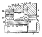
- the accompanying drawing shows a sectional view of a supporting apparatus according to one embodiment of the present invention.
- a supporting apparatus is provided with a rotating shaft 10 as an inner member which is used in a corrosive environment.
- An end portion of the rotating shaft 18 is inserted in a bore 14 which is formed in a supporting member 12 as an outer member.
- a narrower stepped portion 16 is formed on the end portion of the rotating shaft 10, while a wider stepped portion 18 is formed on the inner peripheral surface of the bore 14, facing the stepped portion 16.
- a rolling bearing 20 is interposed between the rotating shaft 10 and the inner peripheral surface of the bore 14, whereby the rotating shaft 10 is rotatably supported.
- the rolling bearing 20 includes an inner ring 22 and an outer ring 24 which are resistant to both heat and corrosion.
- the inner ring 22 is fitted on the outer peripheral surface of the narrower stepped portion 16 so as to abut against a shoulder portion 25 of the rotating shaft 10, and is prevented from slipping off the rotating shaft 10 by a locating snap ring 30 which is fitted on the rotating shaft 10.
- the outer ring 24 is fitted in the wider stepped portion 18 of the bore 14 so as to abut against a shoulder portion 26 of the bore 14, facing the inner ring 22.
- the outer ring 24 is prevented from slipping off the bore 14 by a fixing sleeve 32 which is fitted in the bore 14.
- the inner ring 22 is formed of a ring - shaped raceway track portion 22a and rib portions 22b and 22c which are integrally formed at either end of the raceway track portion 22a so as to project radially outward.
- the outer ring 24 consists of a ring-shaped raceway track portion 24a, a separately formed rib portion 24b located at one end of the raceway track portion 24a on the side of the shoulder portion 26 so as to project radially inward, and a rib portion 24c integrally formed at the other end of the raceway track portion 24a so as to project radially inward.
- a plurality of cylindrical rollers 28 made of heat and corrosion resisting ceramic material are arranged in an annular space defined between the respective raceway track portions 22a and 24a of the inner and outer rings 22 and 24.
- the cylindrical rollers 28 can roll on the outer peripheral surface of the raceway track portion 22a and the inner peripheral surface of the raceway track portion 24a. In rolling action, the cylindrical rollers 28 are guided by the respective inside faces of the rib portions 22b and 22c of the inner ring 22 and the rib portions 24b and 24c of the outer ring 24.
- Corner portions defined by the raceway track portions 22a and 24a and the rib portions 22b, 22c, 24b and 24c have no grinding undercuts as are provided for conventional bearings, and have a radius of curvature substantially equal to or a little smaller than that of the roller chamfers on the end edges of the cylindrical rollers 28.
- the cylindrical rollers 28 may be kept at regular intervals along the circumferential direction of the inner ring 22 by a cage (not shown).
- the cage is naturally formed from heat and corrosion resisting material, such as stainless steel.
- the ceramic material for the cylindrical rollers 28 should preferably be selected among silicon nitride, sialon, or silicon carbide which may be formed by a pressure sintering method, such as a hot pressing process, hot isostatic pressing process, or ambient pressure sintering process.
- a pressure sintering method such as a hot pressing process, hot isostatic pressing process, or ambient pressure sintering process.
- oxides of rare-earth elements as sintering assistants, preferably yttria, and aluminum oxide, if necessary, at an addition rate of 10 % for each.
- the degree of sintering may effectively be improved by adding 10 % or less aluminum nitride or a suitable amount of, preferably 5 % or less, titanium oxide, zirconium oxide, magnesium oxide, molybdenum carbide, spinel, and garnet.
- silicon carbide on the other hand, boron, carbon, aluminum, or a compound of any of these individual elements is preferably added for the improvement of the degree of sintering.
- the supporting apparatus of this embodiment When the supporting apparatus of this embodiment is used in a corrosive environment at a relatively low temperature, e.g., in a melting furnace or electroplating bath for lead or zinc-based alloy, it is necessary only that the cylindrical rollers 28 alone be formed from ceramic material.
- the inner and outer rings 22 and 24 may be formed from stainless steel or other corrosion resisting metal, since the environment is not very corrosive.
- the inner and outer rings 22 and 24, as well as the cylindrical rollers 28, should preferably be formed from ceramic material.
- the inner and outer rings 22 and 24 may be formed from conventional bearing steel coated with a corrosion resisting film, such as carbide of vanadium or compound of chromium, for example Cr2O3.
- the ceramic material used for the inner and outer rings 22 and 24 is identical with that for the cylindrical rollers 28.
- the inner ring 22 is fitted on the rotating shaft 10 by a proper clearance fit, while the outer ring 24 is set in the bore 14 in the supporting member 12 by a transition fit. This is done because ceramics are lower in thermal expansion coefficient than metals, and are more resistant to compressive force but less resistant to tensile force. If the inner ring 22 should be tightly fit on the rotating shaft 10, it would possibly be damaged by a radial tensile force caused by thermal expansion of the rotating shaft 10 during use. It is to be desired therefore that the inner ring 22 and the rotating shaft 10 should be coupled by a clearance fit.
- the outer ring 14 is fitted more tightly in the bore 14 of the supporting member 12, the fitness will be able to be maintained more satisfactorily in proportion after thermal expansion of the supporting member 12 during use.
- the outer ring 24, made of fragile ceramic material may possibly be broken when it is pressed in the bore 14. Accordingly, the outer ring 24 is preferably set in place by a transition fit which permits minimization of the influences of the fitting force and the thermal expansion of the supporting member 12.
- cylindrical rollers 28 are formed from ceramic material, the influences of the thermal expansion of the rotating shaft 10 and the supporting member 12 will be able to be avoided.
- the inner member serves as the rotating member 10, and the outer member as the supporting member 12 supporting the rotating member 10.
- the inner and outer members may be constructed as a supporting shaft and a rotating member supported by the supporting shaft, respectively.
- the inner and outer members 10 and 12 be coupled for relative rotation so that one of them serves as a rotating member and the other as a nonrotating member for supporting the rotating member.
- the manner of arrangement of the rolling bearing according to the above embodiment may also be applied to the case where the inner and outer members constitute the supporting shaft and the rotating member, respectively.
- the rolling elements of the rolling bearing are made of ceramic material, while the inner and outer rings are formed of material resistant to heat and corrosion, e.g., metal coated with a corrosion resisting film such as carbide of vanadium or compound of chromium, or ceramic material, as required.
- the supporting apparatus of the present invention is higher in heat and corrosion resistance than a prior art counterpart, and can avoid damage to the bearing by corrosion even when used in a corrosive environment at high or low temperature, thereby prolonging the life of the bearing.
- the inner member 10 serves as a fixed shaft, while the outer member 12 constitutes a rotating cylinder rotatably supported on the fixed shaft.
- the outer member 12 is fitted with blades for stirring the molten metal. Since the supporting apparatus is highly resistant to corrosion, the rotating cylinder need not be extended above the surface level of the molten metal, and the rotating cylinder and the blades can be supported on substantially the same level by the bearing. Thus, the blades can rotate with less whirling action, and the stirring efficiency is improved for the ease of homogenization of the molten metal.
- the inner and outer members 10 and 12 constitute a rotating roller and a supporting member for supporting the same, respectively.
- the outer member 12 and the bearing 20 are provided at each end of the rotating roller.
- the life of the bearing can be longer, permitting reduction of the frequency of its replacement.
- time loss attributed to the replacement of the bearing can greatly be reduced for improved working efficiency of the plating apparatus.
Landscapes
- Engineering & Computer Science (AREA)
- General Engineering & Computer Science (AREA)
- Mechanical Engineering (AREA)
- Ceramic Engineering (AREA)
- Chemical & Material Sciences (AREA)
- Chemical Kinetics & Catalysis (AREA)
- Electrochemistry (AREA)
- Materials Engineering (AREA)
- Metallurgy (AREA)
- Organic Chemistry (AREA)
- Rolling Contact Bearings (AREA)
- Mounting Of Bearings Or Others (AREA)
- Accessories For Mixers (AREA)
Applications Claiming Priority (2)
| Application Number | Priority Date | Filing Date | Title |
|---|---|---|---|
| JP64844/84 | 1984-03-30 | ||
| JP59064844A JPS60208626A (ja) | 1984-03-30 | 1984-03-30 | 腐食環境下で使用する回転部材支持装置 |
Related Parent Applications (2)
| Application Number | Title | Priority Date | Filing Date |
|---|---|---|---|
| EP85103808.3 Division | 1985-03-29 | ||
| EP85103808A Division EP0158901B1 (de) | 1984-03-30 | 1985-03-29 | Lager für umlaufende Teile |
Publications (2)
| Publication Number | Publication Date |
|---|---|
| EP0303758A2 true EP0303758A2 (de) | 1989-02-22 |
| EP0303758A3 EP0303758A3 (de) | 1990-10-31 |
Family
ID=13269932
Family Applications (2)
| Application Number | Title | Priority Date | Filing Date |
|---|---|---|---|
| EP85103808A Expired - Lifetime EP0158901B1 (de) | 1984-03-30 | 1985-03-29 | Lager für umlaufende Teile |
| EP19880102038 Ceased EP0303758A3 (de) | 1984-03-30 | 1985-03-29 | Lager für umlaufende Teile |
Family Applications Before (1)
| Application Number | Title | Priority Date | Filing Date |
|---|---|---|---|
| EP85103808A Expired - Lifetime EP0158901B1 (de) | 1984-03-30 | 1985-03-29 | Lager für umlaufende Teile |
Country Status (5)
| Country | Link |
|---|---|
| US (1) | US4634300B1 (de) |
| EP (2) | EP0158901B1 (de) |
| JP (1) | JPS60208626A (de) |
| KR (1) | KR890003817B1 (de) |
| DE (1) | DE3587758T2 (de) |
Cited By (4)
| Publication number | Priority date | Publication date | Assignee | Title |
|---|---|---|---|---|
| EP0423313A4 (en) * | 1989-05-08 | 1991-06-05 | Den-Tal-Ez, Inc. | Sterilizable non-lubricated rotary dental and medical instrument |
| EP0864665A4 (de) * | 1996-07-08 | 2001-05-30 | Nippon Steel Hardfacing | Mechanisches material welches einem schmelztauchbad ausgesetzt ist |
| DE102006020078A1 (de) * | 2006-04-29 | 2007-10-31 | Schaeffler Kg | Wälzlager für trockenlaufende oder mediengeschmierte Anwendungen |
| US8092094B2 (en) * | 2006-04-29 | 2012-01-10 | Schaeffler Kg | Rolling bearing slewing connections |
Families Citing this family (42)
| Publication number | Priority date | Publication date | Assignee | Title |
|---|---|---|---|---|
| SE446896B (sv) * | 1985-02-22 | 1986-10-13 | Skf Nova Ab | Universalkopplingsanordning |
| JPS62141314A (ja) * | 1985-12-17 | 1987-06-24 | Agency Of Ind Science & Technol | 高温用セラミツク転がり軸受 |
| US4770549A (en) * | 1986-08-08 | 1988-09-13 | Koyo Seiko Co., Ltd. | Ceramics bearing |
| EP0258845A3 (de) * | 1986-08-29 | 1988-08-17 | Kabushiki Kaisha Nagano Keiki Seisakusho | Keramisches Lager |
| US4729154A (en) * | 1986-12-02 | 1988-03-08 | The Garrett Corporation | Method of making and operating a very high speed marginally lubricated ball thrust bearing |
| US4799810A (en) * | 1986-12-02 | 1989-01-24 | Allied-Signal Inc. | Very high speed marginally lubricated ball thrust bearing |
| JPH0678769B2 (ja) * | 1987-04-13 | 1994-10-05 | 石川島播磨重工業株式会社 | セラミック軸受取付構造 |
| DE3718560A1 (de) * | 1987-06-03 | 1988-12-22 | Uhde Gmbh | Trockenlauffaehige waelzlager |
| EP0304872B1 (de) * | 1987-08-26 | 1991-04-17 | Koyo Seiko Co., Ltd. | Hitzebeständiges Kugellager |
| JP2597103B2 (ja) * | 1987-08-28 | 1997-04-02 | 光洋精工株式会社 | 円筒ころ軸受 |
| JP2554505B2 (ja) * | 1987-08-28 | 1996-11-13 | 光洋精工株式会社 | 円すいころ軸受 |
| US4808014A (en) * | 1987-10-21 | 1989-02-28 | Koyo Seiko Co., Ltd. | Attaching structure for ceramics bearing |
| US5228786A (en) * | 1987-12-15 | 1993-07-20 | Koyo Seiko Co., Ltd. | Full type ball bearing for turbochargers |
| JP2681182B2 (ja) * | 1987-12-15 | 1997-11-26 | 光洋精工株式会社 | 玉軸受 |
| JPH0621330B2 (ja) * | 1988-06-15 | 1994-03-23 | 株式会社日立製作所 | 連続溶融金属めっき装置及びその使用方法 |
| WO1989012760A1 (en) * | 1988-06-17 | 1989-12-28 | Koyo Seiko Co., Ltd. | Crankshaft and connecting rod connecting structure |
| US4906110A (en) * | 1988-07-27 | 1990-03-06 | Balanced Engines, Inc. | Solid-lubricant bearing |
| JPH086751B2 (ja) * | 1988-10-21 | 1996-01-29 | いすゞ自動車株式会社 | 回転機における軸受構造 |
| AU634735B2 (en) * | 1988-12-26 | 1993-03-04 | Wing Highcera Co. Ltd. | Ceramic bearing and manufacturing method |
| US5252130A (en) * | 1989-09-20 | 1993-10-12 | Hitachi, Ltd. | Apparatus which comes in contact with molten metal and composite member and sliding structure for use in the same |
| US4997293A (en) * | 1990-03-22 | 1991-03-05 | Nippon Sharyo Seizo Kabushiki Kaisha | Anti-electrolytic corrosion type rolling bearing |
| US5215386A (en) * | 1990-04-04 | 1993-06-01 | Mpb Corporation | Gimbal bearing |
| JPH0741941Y2 (ja) * | 1990-08-13 | 1995-09-27 | 光洋精工株式会社 | 転がり軸受 |
| JP2638375B2 (ja) * | 1992-02-20 | 1997-08-06 | 株式会社日立製作所 | 連続溶融金属メッキ装置及び連続溶融金属メッキ装置用軸受 |
| JP2584936Y2 (ja) * | 1992-08-19 | 1998-11-11 | 日本精工株式会社 | ターボチャージャー用玉軸受 |
| DE9215104U1 (de) * | 1992-10-23 | 1993-01-07 | Maag Pump Systems AG, Zürich | Zahnradpumpe |
| JP2833947B2 (ja) * | 1992-12-24 | 1998-12-09 | 加茂精工株式会社 | カムによる間欠回転装置 |
| JPH0718027U (ja) * | 1993-09-01 | 1995-03-31 | 日本特殊陶業株式会社 | 窯用台車のベアリング型車輪 |
| KR0143870B1 (ko) * | 1993-12-27 | 1998-07-01 | 사토 후미오 | 고열전도성 질화규소 구조부재 및 반도체 패키지, 히터, 서멀헤드 |
| NL9401873A (nl) * | 1994-11-09 | 1996-06-03 | Skf Ind Trading & Dev | Wentellager met verbeterde slijtage kenmerken. |
| GB9509781D0 (en) * | 1995-05-15 | 1995-07-05 | Rockwool Int | Apparatus for the formation of man-made vitreous fibres |
| JP2000074069A (ja) * | 1998-08-28 | 2000-03-07 | Koyo Seiko Co Ltd | 転がり軸受 |
| US6158894A (en) * | 1999-07-28 | 2000-12-12 | Saint-Gobain Ceramics & Plastics, Inc. | All ceramic bearing |
| FR2798432B1 (fr) * | 1999-09-10 | 2001-11-09 | Snfa | Roulement a billes hybride a billes ceramique et bagues en acier |
| US6464401B1 (en) * | 2001-01-26 | 2002-10-15 | United Technologies Corporation | High load capacity bi-directional tapered roller bearing |
| DE102006050445A1 (de) * | 2006-10-26 | 2008-04-30 | Schaeffler Kg | Wälzlagerkugel, Wälzlager und Verfahren zum Behandeln von Wälzlagerkugeln |
| DE102007015103A1 (de) | 2007-03-29 | 2008-10-02 | Schaeffler Kg | Wälzlager |
| DE102007034381A1 (de) | 2007-07-24 | 2009-01-29 | Schaeffler Kg | Wälzlager mit mindestens einem Schmierkörper sowie Verwendung des Wälzlagers |
| DE102013214240A1 (de) * | 2013-07-22 | 2015-01-22 | Schaeffler Technologies Gmbh & Co. Kg | Propellerblattlagerung |
| CN205669546U9 (zh) * | 2013-11-26 | 2016-12-21 | 三菱电机株式会社 | 蝶阀 |
| WO2019083197A1 (ko) * | 2017-10-25 | 2019-05-02 | 정승환 | 로봇의 자세제어 장치 및 이를 구비한 로봇 |
| KR102487194B1 (ko) * | 2017-12-08 | 2023-01-10 | 현대자동차 주식회사 | 구동모터용 베어링 |
Family Cites Families (15)
| Publication number | Priority date | Publication date | Assignee | Title |
|---|---|---|---|---|
| US2158156A (en) * | 1936-10-10 | 1939-05-16 | Telefunken Gmbh | Ball bearing and balls of ceramic material |
| US2943894A (en) * | 1954-02-10 | 1960-07-05 | United Aircraft Corp | Skid proof bearing |
| US3097897A (en) * | 1961-03-16 | 1963-07-16 | Carborundum Co | Bearing combination |
| US3212834A (en) * | 1962-12-04 | 1965-10-19 | Gen Motors Corp | Zirconium boride bearing |
| US3178241A (en) * | 1963-03-18 | 1965-04-13 | Space Technology And Res Corp | Lubricationless high-temperature bearing |
| GB1296830A (de) * | 1969-02-21 | 1972-11-22 | ||
| US3628836A (en) * | 1969-12-17 | 1971-12-21 | United Aircraft Corp | Roller bearing |
| JPS4921091B1 (de) * | 1970-08-10 | 1974-05-29 | ||
| DE2064318A1 (de) * | 1970-12-29 | 1972-07-06 | Motoren Turbinen Union | Lagerung schwenkbarer Leitschaufeln von thermischen Turbomaschinen |
| FR2127291A6 (de) * | 1971-03-05 | 1972-10-13 | Hurbain Jean | |
| JPS5347860A (en) * | 1976-04-12 | 1978-04-28 | Shizuka Ishizuka | Central hole film of automatic drilling coordinate reader in nc drilling machine for printed circuit board |
| JPS5347861A (en) * | 1976-10-08 | 1978-04-28 | Hitachi Ltd | Position detector of control type |
| CH624741A5 (en) * | 1977-01-21 | 1981-08-14 | Suisse Horlogerie Rech Lab | Precision rolling bearing |
| EP0100380B1 (de) * | 1981-02-05 | 1987-06-16 | Sumitomo Electric Industries Limited | Verfahren zur plastischen Verformung von Nichteisenmetallen |
| JPS58113628A (ja) * | 1981-12-28 | 1983-07-06 | Masataka Watanabe | ころがり軸受 |
-
1984
- 1984-03-30 JP JP59064844A patent/JPS60208626A/ja active Pending
-
1985
- 1985-03-27 KR KR1019850002032A patent/KR890003817B1/ko not_active Expired
- 1985-03-29 US US90/002188A patent/US4634300B1/en not_active Expired - Lifetime
- 1985-03-29 EP EP85103808A patent/EP0158901B1/de not_active Expired - Lifetime
- 1985-03-29 EP EP19880102038 patent/EP0303758A3/de not_active Ceased
- 1985-03-29 DE DE3587758T patent/DE3587758T2/de not_active Expired - Lifetime
Non-Patent Citations (1)
| Title |
|---|
| "Comprehensive Bibliography of Iron-Making Machines & Equipment", 25 November 1976, JUKOGYO SHINBUN PUBLISHING CO. |
Cited By (4)
| Publication number | Priority date | Publication date | Assignee | Title |
|---|---|---|---|---|
| EP0423313A4 (en) * | 1989-05-08 | 1991-06-05 | Den-Tal-Ez, Inc. | Sterilizable non-lubricated rotary dental and medical instrument |
| EP0864665A4 (de) * | 1996-07-08 | 2001-05-30 | Nippon Steel Hardfacing | Mechanisches material welches einem schmelztauchbad ausgesetzt ist |
| DE102006020078A1 (de) * | 2006-04-29 | 2007-10-31 | Schaeffler Kg | Wälzlager für trockenlaufende oder mediengeschmierte Anwendungen |
| US8092094B2 (en) * | 2006-04-29 | 2012-01-10 | Schaeffler Kg | Rolling bearing slewing connections |
Also Published As
| Publication number | Publication date |
|---|---|
| EP0158901B1 (de) | 1994-03-02 |
| EP0158901A1 (de) | 1985-10-23 |
| DE3587758T2 (de) | 1994-07-07 |
| US4634300A (en) | 1987-01-06 |
| KR850007107A (ko) | 1985-10-30 |
| JPS60208626A (ja) | 1985-10-21 |
| EP0303758A3 (de) | 1990-10-31 |
| US4634300B1 (en) | 1993-05-18 |
| DE3587758D1 (de) | 1994-04-07 |
| KR890003817B1 (ko) | 1989-10-05 |
Similar Documents
| Publication | Publication Date | Title |
|---|---|---|
| US4634300A (en) | Rotating member supporting apparatus | |
| EP0556833B1 (de) | Vorrichtung zum kontinuierlichen Verzinken und Gleitlagerstruktur dafür | |
| JP3070757B2 (ja) | 連続溶融金属メツキ装置、連続溶融金属メツキ装置の製造方法、連続溶融金属メツキ装置用軸受、及び、連続溶融金属メツキ装置用ロール | |
| EP0555836A2 (de) | Vorrichtung zum kontinuierlichen Heisstauchen und Gleitflächen tragende Struktur dafür | |
| JP3191558B2 (ja) | 摺動構造物とそれを用いた連続溶融金属メッキ装置 | |
| EP1696047A1 (de) | Rolle für bad zum beschichten mit schmelzflüssigem metall | |
| CN100414128C (zh) | 轧辊支撑轴承 | |
| EP0524851A1 (de) | Verfahren zum Beschichten von metallischen Bändern mit Metall oder Metallegierungen und Führungselemente zu dessen Durchführung | |
| JPH0758098B2 (ja) | 高温,腐食等特殊環境で使用する軸受 | |
| JP2963451B2 (ja) | 転がり軸受 | |
| JPH01220719A (ja) | 転がり軸受 | |
| AU2002358749A1 (en) | Casting roll and a method for producing a casting roll | |
| JP2607630B2 (ja) | スリーブ組立て式ロール及びそれを用いた設備 | |
| US6729766B2 (en) | Retention of ceramic bearings | |
| JPH01220718A (ja) | 転がり軸受 | |
| AU711657B2 (en) | Equipment for use in baths disposed within molten metal plating baths | |
| JP2000309863A (ja) | 溶融金属浴用円筒滑り軸受け | |
| KR100568340B1 (ko) | 용융금속 도금설비의 침적롤용 저널베어링 | |
| JPH0134976Y2 (de) | ||
| JP3376922B2 (ja) | 摺動構造物及び摺動方法並びに連続溶融亜鉛めっき装置 | |
| JP4678581B2 (ja) | 溶融金属めっき浴用ロール | |
| JPH05221756A (ja) | 摺動用セラミックス材及びその製造方法と用途 | |
| JP2902542B2 (ja) | ロール軸受 | |
| JP3567497B2 (ja) | 溶融金属中で使用される転がり軸受 | |
| JPH09217158A (ja) | 転がり軸受 |
Legal Events
| Date | Code | Title | Description |
|---|---|---|---|
| PUAI | Public reference made under article 153(3) epc to a published international application that has entered the european phase |
Free format text: ORIGINAL CODE: 0009012 |
|
| 17P | Request for examination filed |
Effective date: 19880308 |
|
| AC | Divisional application: reference to earlier application |
Ref document number: 158901 Country of ref document: EP |
|
| AK | Designated contracting states |
Kind code of ref document: A2 Designated state(s): DE FR GB SE |
|
| PUAL | Search report despatched |
Free format text: ORIGINAL CODE: 0009013 |
|
| AK | Designated contracting states |
Kind code of ref document: A3 Designated state(s): DE FR GB SE |
|
| 17Q | First examination report despatched |
Effective date: 19910704 |
|
| STAA | Information on the status of an ep patent application or granted ep patent |
Free format text: STATUS: THE APPLICATION HAS BEEN REFUSED |
|
| 18R | Application refused |
Effective date: 19930712 |
|
| APAF | Appeal reference modified |
Free format text: ORIGINAL CODE: EPIDOSCREFNE |