EP0293586B1 - Encreur compartimenté pour machine à imprimer flexographique - Google Patents
Encreur compartimenté pour machine à imprimer flexographique Download PDFInfo
- Publication number
- EP0293586B1 EP0293586B1 EP88106301A EP88106301A EP0293586B1 EP 0293586 B1 EP0293586 B1 EP 0293586B1 EP 88106301 A EP88106301 A EP 88106301A EP 88106301 A EP88106301 A EP 88106301A EP 0293586 B1 EP0293586 B1 EP 0293586B1
- Authority
- EP
- European Patent Office
- Prior art keywords
- anilox roller
- ink duct
- strip
- blades
- liquid
- Prior art date
- Legal status (The legal status is an assumption and is not a legal conclusion. Google has not performed a legal analysis and makes no representation as to the accuracy of the status listed.)
- Expired - Lifetime
Links
- 239000000976 ink Substances 0.000 claims description 83
- 238000007774 anilox coating Methods 0.000 claims description 63
- XLYOFNOQVPJJNP-UHFFFAOYSA-N water Substances O XLYOFNOQVPJJNP-UHFFFAOYSA-N 0.000 claims description 32
- 239000007788 liquid Substances 0.000 claims description 27
- 229920002379 silicone rubber Polymers 0.000 claims description 14
- 239000004945 silicone rubber Substances 0.000 claims description 14
- 238000007789 sealing Methods 0.000 claims description 11
- 239000000463 material Substances 0.000 claims description 7
- 238000000034 method Methods 0.000 claims description 4
- 230000008569 process Effects 0.000 claims description 4
- 230000004323 axial length Effects 0.000 claims 1
- 238000003780 insertion Methods 0.000 claims 1
- 230000037431 insertion Effects 0.000 claims 1
- 230000000717 retained effect Effects 0.000 claims 1
- 238000009738 saturating Methods 0.000 claims 1
- 239000000126 substance Substances 0.000 claims 1
- 239000010408 film Substances 0.000 description 14
- 229920001971 elastomer Polymers 0.000 description 7
- 230000008901 benefit Effects 0.000 description 4
- 238000001035 drying Methods 0.000 description 4
- -1 polytetrafluoroethylene Polymers 0.000 description 4
- 229920001343 polytetrafluoroethylene Polymers 0.000 description 4
- 239000004810 polytetrafluoroethylene Substances 0.000 description 4
- 238000000926 separation method Methods 0.000 description 4
- 239000010409 thin film Substances 0.000 description 4
- 239000003086 colorant Substances 0.000 description 3
- 238000004140 cleaning Methods 0.000 description 2
- 230000006835 compression Effects 0.000 description 2
- 238000007906 compression Methods 0.000 description 2
- 230000000694 effects Effects 0.000 description 2
- 230000005012 migration Effects 0.000 description 2
- 238000013508 migration Methods 0.000 description 2
- 239000004033 plastic Substances 0.000 description 2
- 239000004821 Contact adhesive Substances 0.000 description 1
- 239000004677 Nylon Substances 0.000 description 1
- 238000005299 abrasion Methods 0.000 description 1
- 230000009471 action Effects 0.000 description 1
- 238000004026 adhesive bonding Methods 0.000 description 1
- 238000001704 evaporation Methods 0.000 description 1
- 238000002474 experimental method Methods 0.000 description 1
- 230000005484 gravity Effects 0.000 description 1
- 230000003993 interaction Effects 0.000 description 1
- 239000000314 lubricant Substances 0.000 description 1
- 238000004519 manufacturing process Methods 0.000 description 1
- 229910052751 metal Inorganic materials 0.000 description 1
- 239000000203 mixture Substances 0.000 description 1
- 238000012986 modification Methods 0.000 description 1
- 230000004048 modification Effects 0.000 description 1
- 229920001778 nylon Polymers 0.000 description 1
- 239000005022 packaging material Substances 0.000 description 1
- 238000004806 packaging method and process Methods 0.000 description 1
- 238000005192 partition Methods 0.000 description 1
- 230000000149 penetrating effect Effects 0.000 description 1
- 229920001296 polysiloxane Polymers 0.000 description 1
- 238000012552 review Methods 0.000 description 1
- 238000005096 rolling process Methods 0.000 description 1
- 239000003566 sealing material Substances 0.000 description 1
- 239000002904 solvent Substances 0.000 description 1
- 238000009827 uniform distribution Methods 0.000 description 1
Images

Classifications
-
- B—PERFORMING OPERATIONS; TRANSPORTING
- B41—PRINTING; LINING MACHINES; TYPEWRITERS; STAMPS
- B41F—PRINTING MACHINES OR PRESSES
- B41F31/00—Inking arrangements or devices
- B41F31/02—Ducts, containers, supply or metering devices
- B41F31/027—Ink rail devices for inking ink rollers
-
- B—PERFORMING OPERATIONS; TRANSPORTING
- B41—PRINTING; LINING MACHINES; TYPEWRITERS; STAMPS
- B41F—PRINTING MACHINES OR PRESSES
- B41F31/00—Inking arrangements or devices
- B41F31/18—Inking arrangements or devices for inking selected parts of printing formes
-
- B—PERFORMING OPERATIONS; TRANSPORTING
- B41—PRINTING; LINING MACHINES; TYPEWRITERS; STAMPS
- B41P—INDEXING SCHEME RELATING TO PRINTING, LINING MACHINES, TYPEWRITERS, AND TO STAMPS
- B41P2200/00—Printing processes
- B41P2200/10—Relief printing
- B41P2200/12—Flexographic printing
Definitions
- the invention relates to a divided ink fountain, in particular for a flexographic printing machine, the ink fountain being divided axially into different zones by means of separating elements in order to enable the use of different colored printing inks for corresponding zones of an application or anilox roller and the ink fountain interacts with doctor blades.”
- a low-friction surface is attached to the edge which abuts the doctor blade, the sealing element bridging the space between the doctor blades and the element being fitted to the circumference of the ductor or the trough roller.
- the doctor blades extend axially beyond the sealing elements.
- the separating plates and the sealing elements can be mounted on units which are effectively arranged along the ink fountain and thus along the ductor or the trough roller, in positions chosen in such a way as the axial extension of the differently colored ink zones requires.
- the invention has the task of creating a flexible device for separating axial zones on an anilox roller for a flexographic printing machine, so that printing inks with different features, for example in different colors, can be applied to the zones in question without overlap, the Setup is simple and inexpensive and ensures effective sealing of the axial zones against each other.
- the strip element is backed with, for example, silicone rubber with a low durometer value. This enables the seal to set itself independently of the direction of rotation of the anilox roller.
- the ink system is arranged so that a holding structure for the separating strip elements, for the rubber backing and for the felt pads or, preferably, the entire ink fountain can be moved so that either one of the two doctor blades with the Anilox roller is in contact, depending on the direction of rotation of the anilox roller, and that the movement can also be carried out so that both doctor blades release the anilox roller, while the separating element and, preferably, the pads remain in contact with the surface of the anilox roller.
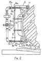
- Fig. 2 is a schematic section perpendicular to the axis of an anilox roller, showing the ink separator according to the present invention.
- the separating element is narrow and extends over a part the circumference of the anilox roller 10.
- the separating element 2 is designed with a recess 13, into which a strip element 3 is inserted, the r is supported on the back by a backing 5 made of silicone rubber.
- a width of the elements 3 and 5 of approximately 15 mm is suitable.
- the silicone rubber backing element 5 distributes the pressure of the strip element 3 evenly over the circumference of the anilox roller.
- the compressive force in the silicone rubber can be generated by pushing against the anilox roller 10.
- the pressure of the strip element 3 against the anilox roller can thus be controlled.
- the ink migration across the parting plane is effectively prevented because the liquid film of the liquid only allows it to remain between the anilox roller and the strip element 3 and, on the other hand, prevents ink from penetrating between the strip element and the anilox roller.
- the migration of printing ink with a certain property, for example a certain color, into the printing ink with another property, for example a different color, is thus effectively prevented.
- a silicone rubber with low hardness for example a closed-cell silicone rubber with a degree of hardness (durometer) 30, arranged behind the strip element, ensures a constant, uniform sealing pressure against the surface of the anilox roller.
- the silicone rubber with low hardness between the wall of the separating element 2 and the strip element 3 also provides an effective seal at the corners of the doctor blades. This type of silicone rubber allows compression of about 20%, which is the reason for the slight expansion 24, 25 of the silicone rubber around the doctor ends and doctor corners.
- the common axis 50 runs along the inking unit, in parallel to the color trough 11. You can swing, as indicated by arrow 51.
- the axis 50 is coupled with the aid of an angle lever 52 to the support rod 41 or the bracket 40 of the tilting device of the separating element 2.
- the lower drip system can be switched off by changing the position of the valve 18 and the lower felt pad 31 can be removed.
- the upper felt pad 21 remains in place and the upper drip system is turned on.
- the unwetted pillow should be removed so that it does not dry out. Removing the felt pad is easy, you only need to pull it out, you can also loosen the fastening screws that hold the relevant clamping plate 22, 32, and then take out the respective felt strips 21, 31.
- the roller 10 can run at speeds of more than 800 rpm, for example.
- the roller 10 can continue to idle are left, for example at 30 rpm, the color being continuously circulated between the inlet openings 45 and the outlet openings 46 - only shown in different color zones in FIG. 1 - while the color zones remain separate from one another. After tilting the shaft 50 counterclockwise of the arrow 51, both doctor blades 23 and 33 come out of engagement with the anilox roller 10.
Landscapes
- Inking, Control Or Cleaning Of Printing Machines (AREA)
Claims (11)
- Encrier compartimenté, (11) en particulier pour une presse flexographique dans laquelle l'encrier (11) est subdivisé axialement en différentes zones (10a, 10b), au moyens d'éléments séparateurs (2), pour permettre d'utiliser des encres d'imprimerie de différentes couleurs pour les zones correspondantes d'un rouleau encreur ou anilox (10), et l'encrier (11) coopère avec des racles (23, 33), caractérisé en ce que chaque élément séparateur (2) définit une structure de support pour une bande (3) et en ce qu'un élément tampon (21, 31) fait d'une substance poreuse disposé en coïncidence avec une bande (3) est prévu pour cet élément, en ce qu'il est prévu des moyens (14a, 15a, 14b, 15b) d'approvisionnement de liquide qui sont en communication avec chaque élément tampon (21, 31), en ce que chaque bande (3) présente une surface incurvée qui est en appui contre la surface du rouleau anilox (10), est adaptée à cette surface et s'étend sur une partie de la circonférence du rouleau anilox (10), en ce que l'élément tampon (21, 31) et les moyens (14a, 15a, 14b, 15b) d'approvisionnement de liquide sont prévus pour interposer un film hydraulique fait d'un liquide séparateur entre la surface incurvée de la bande (3) et la surface du rouleau anilox (10), de telle manière que le film hydraulique ne forme une bande de liquide que sensiblement dans la région de la circonférence du rouleau anilox (10) en face de laquelle se trouve la face incurvée de la bande (3) considérée, de sorte que chaque bande (3) flotte sur le rouleau anilox (10).
- Encrier compartimenté selon la revendication 1, caractérisé en ce que le liquide en question est l'eau.
- Encrier compartimenté selon la revendication 1, caractérisé en ce que l'élément tampon (21, 31) est composé de deux éléments pouvant s'imprégner de liquide, munis chacun d'une conduite séparée (14a, 15a et 14b, 15b) d'approvisionnement de liquide, les éléments (21, 31) considérés étant disposés aux extrémités extérieures des bandes (3)
- Encrier compartimenté selon la revendication 1 ou 3, caractérisé en ce que les éléments tampons (21, 31) précités sont faits de feutre.
- Encrier compartimenté selon la revendication 1, caractérisé en ce qu'il est prévu, pour chacune des bandes (3), un élément de doublage arrière (5) qui est disposé adjacent à la bande (3) contre la face de dette dernière qui est à l'opposé du rouleau anilox (10), chaque élément de doublage arrière (5) comprenant une matière compressible.
- Encrier compartimenté selon la revendication 5, caractérisé en ce que la matière compressible précitée est le caoutchouc de silicone.
- Encrier compartimenté selon une des revendications précédentes, caractérisé en ce que chaque élément séparateur (2) est réalisé avec un évidement (13) qui s'étend sur une partie de la circonférence du rouleau anilox (12), et l'élément de doublage arrière (5) est tenu dans l'évidement (13).
- Encrier compartimenté selon une des revendications précédentes, caractérisé en ce que les racles (23, 33) sont subdivisées dans leur direction axiale par les bandes (3), les racles (23, 33) sont en contact par une partie de leur arête avec les éléments de doublage arrière (5) en matière compressible, de sorte que la matière compressible se bombe contre les racles (23, 33), et les racles (23, 33) sont appuyées à joint étanche contre les éléments de doublage arrière (5).
- Encrier compartimenté selon la revendication 5, caractérisé en ce qu'il est prévu des moyens (41, 50, 52) qui donnent appui à l'encrier (11) en laissant ce dernier mobile, pour permettre de mettre sélectivement les racles (23, 53) en appui contre le rouleau anilox (10) ou d'écarter les racles (23, 33) d'une petite distance qui suffit pour que les racles (23, 33) soient dégagées du rouleau anilox (10), alors que le contact élastique entre la bande (3) et le rouleau anilox (10) reste conservé et que le dépôt de liquide séparateur sur le rouleau anilox (10) à l'aide des moyens précités (14a, 15a ou 14b, 15b) d'approvisionnement de liquide peut se poursuivre.
- Procédé pour isoler mutuellement à joint étanche des encres d'imprimerie possédant des propriétés différentes contenues dans des zones axiales (10a, 10b) d'un rouleau anilox (10) dans le cas d'un encrier compartimenté (11), dans lequel l'encrier (11) est subdivisé axialement en différentes zones (10a, 10b) au moyen d'éléments séparateurs (2) pour permettre d'utiliser des encres d'imprimerie de différentes couleurs pour les zones correspondantes d'un rouleau encreur ou rouleau anilox (10) et l'encrier (11) coopère avec des racles (23, 33), caractérisé par l'interposition d'une bande circonférentielle d'un film de liquide séparateur entre les zones précitées (10a, 10b) réalisée par application d'un tampon poreux (21, 31) du type mèche contre la surface du rouleau anilox (10), saturation dudit tampon (21, 31) par le liquide séparateur et glissement des bandes (3) sur ledit film.
- Procédé selon la revendication 10, caractérisé en ce que, pour le liquide précité, on utilise l'eau.
Applications Claiming Priority (2)
| Application Number | Priority Date | Filing Date | Title |
|---|---|---|---|
| US07/056,785 US4796528A (en) | 1987-05-29 | 1987-05-29 | Separated ink fountain for a flexographic printing machine |
| US56785 | 1987-05-29 |
Publications (3)
| Publication Number | Publication Date |
|---|---|
| EP0293586A2 EP0293586A2 (fr) | 1988-12-07 |
| EP0293586A3 EP0293586A3 (en) | 1990-02-28 |
| EP0293586B1 true EP0293586B1 (fr) | 1992-12-02 |
Family
ID=22006570
Family Applications (1)
| Application Number | Title | Priority Date | Filing Date |
|---|---|---|---|
| EP88106301A Expired - Lifetime EP0293586B1 (fr) | 1987-05-29 | 1988-04-20 | Encreur compartimenté pour machine à imprimer flexographique |
Country Status (5)
| Country | Link |
|---|---|
| US (1) | US4796528A (fr) |
| EP (1) | EP0293586B1 (fr) |
| JP (1) | JP2716457B2 (fr) |
| CA (1) | CA1299915C (fr) |
| DE (1) | DE3876293D1 (fr) |
Families Citing this family (31)
| Publication number | Priority date | Publication date | Assignee | Title |
|---|---|---|---|---|
| US5012736A (en) * | 1987-09-21 | 1991-05-07 | Paper Converting Machine Company | Sealing assembly for liquid fountain |
| US5125341A (en) * | 1991-05-15 | 1992-06-30 | Paper Converting Machine Company | Ink unit for printing press and method |
| US5150651A (en) * | 1991-06-10 | 1992-09-29 | Flores Carlos R | Doctor-blade assembly for flexographic press |
| US5253582A (en) * | 1991-09-19 | 1993-10-19 | Rockwell International Corporation | Sealing device for a printing press |
| US5230286A (en) * | 1991-10-11 | 1993-07-27 | De La Rue Giori, S.A. | Inking unit for a printing machine |
| US5243907A (en) * | 1992-01-22 | 1993-09-14 | The Langston Corporation | Divider seal for split-fountain chambered doctor blade for a flexographic printing press |
| US5410961A (en) * | 1992-12-30 | 1995-05-02 | Fit Group, Inc. | Fountain assembly |
| DE4315595C2 (de) * | 1993-05-11 | 1995-02-16 | Roland Man Druckmasch | Einsatz für Keilfarbkästen von Druckmaschinen |
| DE4447123C1 (de) * | 1994-12-29 | 1996-04-11 | Koenig & Bauer Albert Ag | Kammerrakel für eine Rotationsdruckmaschine |
| US5630363A (en) | 1995-08-14 | 1997-05-20 | Williamson Printing Corporation | Combined lithographic/flexographic printing apparatus and process |
| US5651316A (en) * | 1995-10-02 | 1997-07-29 | Howard W. DeMoore | Retractable printing/coating unit operable on the plate and blanket cylinders simultaneously from the dampener side of the first printing unit or any consecutive printing unit of any rotary offset printing press |
| US5598777A (en) * | 1995-10-02 | 1997-02-04 | Howard W. DeMoore | Retractable printing/coating unit operable on the plate and blanket cylinders |
| US5826509A (en) * | 1995-10-18 | 1998-10-27 | Deneka; P. Kenneth | Printing coating head device |
| US5983797A (en) * | 1997-11-17 | 1999-11-16 | Howard W. DeMoore | End seal engaging bearer of anilox roller assembly |
| US6029574A (en) * | 1998-09-30 | 2000-02-29 | Heidelberger Druckmaschinen Ag | Dual ink supply system |
| DE10136028C5 (de) * | 2001-07-25 | 2016-03-17 | manroland sheetfed GmbH | Verfahren und Vorrichtung zum Dosieren eines flüssigen Mediums in einer Verarbeitungsmaschine |
| US7178461B2 (en) * | 2002-12-09 | 2007-02-20 | Color Control Corp. | Ink fountain assembly with non-tilt cheeks and liner replacement mechanism |
| JP4533275B2 (ja) * | 2005-08-11 | 2010-09-01 | キヤノン株式会社 | 液体塗布装置およびインクジェット記録装置 |
| CN101400518A (zh) * | 2006-03-09 | 2009-04-01 | 图像印刷与科技公司 | 用于高粘度墨的刮刀腔 |
| US7487724B1 (en) | 2006-05-09 | 2009-02-10 | Larry William Evans | Liquid transfer arrangement for applying a printing liquid to a printing surface |
| DK176626B1 (da) * | 2007-08-21 | 2008-12-01 | Tresu Anlaeg As | Pakning til kammerrakel |
| JP2009214302A (ja) * | 2008-03-07 | 2009-09-24 | Toppan Printing Co Ltd | 凸版印刷装置 |
| WO2014159780A2 (fr) | 2013-03-13 | 2014-10-02 | Probity Engineering, Llc | Appareil encreur et procédé de réglage du débit d'encre pour appareil de flexographie |
| US9807871B2 (en) | 2013-08-28 | 2017-10-31 | 3M Innovative Properties Company | Electronic assembly with fiducial marks for precision registration during subsequent processing steps |
| JP5507748B1 (ja) * | 2013-10-01 | 2014-05-28 | 大倉工業株式会社 | 包装体用フィルムの製造方法 |
| JP5587482B1 (ja) * | 2013-10-28 | 2014-09-10 | 大倉工業株式会社 | 包装用フィルムの製造方法 |
| EP3193045B1 (fr) * | 2016-01-14 | 2019-03-20 | Windmöller & Hölscher KG | Élément d'étanchéite pour étancher les faces laterales d'une chambre à racle |
| DE102018129093A1 (de) * | 2018-11-19 | 2020-05-20 | Windmöller & Hölscher Kg | Drainbox für eine Rakelkammer |
| DE102022121229A1 (de) * | 2022-08-23 | 2024-02-29 | Koenig & Bauer Ag | Farbwerk mit einer Schmiermittelzufuhr und Verfahren zum Abdichten einer Farbwanne |
| US12311652B2 (en) * | 2023-09-12 | 2025-05-27 | Eastman Kodak Company | Inking system with plurality of fountain roller elements |
| CN117734295A (zh) * | 2023-12-30 | 2024-03-22 | 武汉华威科智能技术有限公司 | 一种柔性传感器的柔版印刷机构 |
Family Cites Families (15)
| Publication number | Priority date | Publication date | Assignee | Title |
|---|---|---|---|---|
| US1919283A (en) * | 1931-12-22 | 1933-07-25 | Martin J Troy | Ink fountain divider and pad |
| US2301535A (en) * | 1941-12-09 | 1942-11-10 | Meredith Publishing Company | Fountain divider |
| GB604568A (en) * | 1944-11-27 | 1948-07-06 | Goss Printing Press Co Ltd | Improvements in or relating to ink fountains for use in printing presses |
| US3032007A (en) * | 1959-05-01 | 1962-05-01 | Francis W Mccauliff | Coating head dike |
| DE1224327B (de) * | 1963-03-28 | 1966-09-08 | Albert Schnellpressen | Farbkasten fuer Tiefdruckrotationsmaschinen |
| DE1961033B2 (de) * | 1969-12-05 | 1971-10-07 | Maschinenfabrik Augsburg Nürnberg AG, 8900 Augsburg | Farbabteilungsvorrichtung zwischen verschiedene farben foer dernden bereichen von farbwalzen an druckmaschinen |
| US3831517A (en) * | 1972-12-22 | 1974-08-27 | Dayco Corp | Fountain divider |
| JPS528722A (en) * | 1975-07-10 | 1977-01-22 | Denki Onkyo Co Ltd | Fly-back trans former |
| US4165688A (en) * | 1977-04-14 | 1979-08-28 | Magna-Graphics Corporation | Ink dam for printing press |
| FR2421732A1 (fr) * | 1978-04-07 | 1979-11-02 | Sarda Jean Lucien | Procede et mecanisme d'encrage en une ou plusieurs couleurs pour impressions typographiques, offset ou autres |
| DE8126229U1 (de) * | 1981-09-09 | 1986-08-21 | Windmöller & Hölscher, 4540 Lengerich | Spülfarbwerk für eine Rotationsdruckmaschine |
| DE3241124A1 (de) * | 1982-11-06 | 1984-05-10 | Koenig & Bauer AG, 8700 Würzburg | Farbabteilkeil in einem farbkasten einer rotationsdruckmaschine |
| DE3320638C2 (de) * | 1983-06-08 | 1986-10-16 | Koenig & Bauer AG, 8700 Würzburg | Farbabteileinrichtung an Farbkastenwalzen von Druckmaschinen |
| DE3505598C2 (de) * | 1984-10-30 | 1986-08-14 | Windmöller & Hölscher, 4540 Lengerich | Spülfarbwerk mit geteilter Farbkammerrakel |
| DE3539759C1 (de) * | 1985-11-09 | 1987-04-02 | Roland Man Druckmasch | Farbteiler fuer ein Flexo-Farbwerk |
-
1987
- 1987-05-29 US US07/056,785 patent/US4796528A/en not_active Expired - Fee Related
-
1988
- 1988-04-20 DE DE8888106301T patent/DE3876293D1/de not_active Expired - Fee Related
- 1988-04-20 EP EP88106301A patent/EP0293586B1/fr not_active Expired - Lifetime
- 1988-05-26 CA CA000567758A patent/CA1299915C/fr not_active Expired - Lifetime
- 1988-05-30 JP JP63130494A patent/JP2716457B2/ja not_active Expired - Lifetime
Also Published As
| Publication number | Publication date |
|---|---|
| CA1299915C (fr) | 1992-05-05 |
| EP0293586A2 (fr) | 1988-12-07 |
| DE3876293D1 (de) | 1993-01-14 |
| JPS63312149A (ja) | 1988-12-20 |
| US4796528A (en) | 1989-01-10 |
| EP0293586A3 (en) | 1990-02-28 |
| JP2716457B2 (ja) | 1998-02-18 |
Similar Documents
| Publication | Publication Date | Title |
|---|---|---|
| EP0293586B1 (fr) | Encreur compartimenté pour machine à imprimer flexographique | |
| DE3146223C2 (de) | Feucht-Farbwerk für Offsetdruckmaschinen | |
| DE3823340C1 (fr) | ||
| DE2526466A1 (de) | Farbauftragsvorrichtung fuer eine tiefdruckmaschine | |
| DE4012825A1 (de) | Kammerrakel | |
| DE3814049A1 (de) | Verfahren und einrichtung fuer den flexo-druck | |
| EP0327832B1 (fr) | Encrage pelliculaire supérieur pour presses rotatives | |
| DE69117844T2 (de) | Verbessertes Drucksystem ohne Farbmesser zum lithographischem Drucken ohne Farbmesser | |
| DE19529205C2 (de) | Feuchtwerk für eine Offsetdruckmaschine | |
| DE1561113A1 (de) | Feuchtwerk fuer Offsetdruckmaschinen | |
| DE69834752T2 (de) | Farbzuführrolle für drucker | |
| DE29706932U1 (de) | Feuchtwerk für eine Offsetdruckmaschine | |
| DE19529204C2 (de) | Feuchtwerk für eine Offsetdruckmaschine | |
| EP0657282B1 (fr) | Dispositif d'encrage | |
| DE2432576B2 (de) | Feuchtreiber in feuchtwerken | |
| DE3025546A1 (de) | Vorrichtung zum aufbringen eines fluessigen bzw. halbfluessigen mediums auf die druckplatte einer druckmaschine, insbesondere offsetdruckmaschine | |
| DE8224875U1 (de) | Farbwerk für Offsetdruckmaschinen | |
| DE10020227B4 (de) | Offsetdruckwerk für eine Druckmaschine | |
| EP1534522A1 (fr) | Systemes d'encrage de machines d'impression rotative | |
| DE10103842A1 (de) | Farbwerk in einer Druckmaschine | |
| DE3127880A1 (de) | "farbwerk" | |
| DE10303608B4 (de) | Verfahren für einen stabilen Maschinenlauf an Druckeinheiten einer Rotationsdruckmaschine für den Betrieb mit teilbreitem Bedruckstoff | |
| DE19645169A1 (de) | Verfahren zur Reinigung von Zylindern und Walzen in einer Druckmaschine | |
| DE1240887B (de) | Farbwerk fuer eine Rotationstiefdruckmaschine | |
| EP3170665B1 (fr) | Procédé de fonctionnement d'une imprimante comprenant un cylindre tramé |
Legal Events
| Date | Code | Title | Description |
|---|---|---|---|
| PUAI | Public reference made under article 153(3) epc to a published international application that has entered the european phase |
Free format text: ORIGINAL CODE: 0009012 |
|
| AK | Designated contracting states |
Kind code of ref document: A2 Designated state(s): CH DE FR GB IT LI SE |
|
| PUAL | Search report despatched |
Free format text: ORIGINAL CODE: 0009013 |
|
| AK | Designated contracting states |
Kind code of ref document: A3 Designated state(s): CH DE FR GB IT LI SE |
|
| 17P | Request for examination filed |
Effective date: 19900131 |
|
| 17Q | First examination report despatched |
Effective date: 19910703 |
|
| ITF | It: translation for a ep patent filed | ||
| GRAA | (expected) grant |
Free format text: ORIGINAL CODE: 0009210 |
|
| AK | Designated contracting states |
Kind code of ref document: B1 Designated state(s): CH DE FR GB IT LI SE |
|
| REF | Corresponds to: |
Ref document number: 3876293 Country of ref document: DE Date of ref document: 19930114 |
|
| ET | Fr: translation filed | ||
| PGFP | Annual fee paid to national office [announced via postgrant information from national office to epo] |
Ref country code: GB Payment date: 19930315 Year of fee payment: 6 |
|
| PGFP | Annual fee paid to national office [announced via postgrant information from national office to epo] |
Ref country code: FR Payment date: 19930317 Year of fee payment: 6 |
|
| PGFP | Annual fee paid to national office [announced via postgrant information from national office to epo] |
Ref country code: SE Payment date: 19930322 Year of fee payment: 6 |
|
| GBT | Gb: translation of ep patent filed (gb section 77(6)(a)/1977) |
Effective date: 19930301 |
|
| PLBE | No opposition filed within time limit |
Free format text: ORIGINAL CODE: 0009261 |
|
| STAA | Information on the status of an ep patent application or granted ep patent |
Free format text: STATUS: NO OPPOSITION FILED WITHIN TIME LIMIT |
|
| 26N | No opposition filed | ||
| PG25 | Lapsed in a contracting state [announced via postgrant information from national office to epo] |
Ref country code: GB Effective date: 19940420 |
|
| PG25 | Lapsed in a contracting state [announced via postgrant information from national office to epo] |
Ref country code: SE Effective date: 19940421 |
|
| GBPC | Gb: european patent ceased through non-payment of renewal fee |
Effective date: 19940420 |
|
| PG25 | Lapsed in a contracting state [announced via postgrant information from national office to epo] |
Ref country code: FR Effective date: 19941229 |
|
| EUG | Se: european patent has lapsed |
Ref document number: 88106301.0 Effective date: 19941110 |
|
| REG | Reference to a national code |
Ref country code: FR Ref legal event code: ST |
|
| PGFP | Annual fee paid to national office [announced via postgrant information from national office to epo] |
Ref country code: DE Payment date: 19970320 Year of fee payment: 10 |
|
| PGFP | Annual fee paid to national office [announced via postgrant information from national office to epo] |
Ref country code: CH Payment date: 19970326 Year of fee payment: 10 |
|
| PG25 | Lapsed in a contracting state [announced via postgrant information from national office to epo] |
Ref country code: LI Free format text: LAPSE BECAUSE OF NON-PAYMENT OF DUE FEES Effective date: 19980430 Ref country code: CH Free format text: LAPSE BECAUSE OF NON-PAYMENT OF DUE FEES Effective date: 19980430 |
|
| REG | Reference to a national code |
Ref country code: CH Ref legal event code: PL |
|
| PG25 | Lapsed in a contracting state [announced via postgrant information from national office to epo] |
Ref country code: DE Free format text: LAPSE BECAUSE OF NON-PAYMENT OF DUE FEES Effective date: 19990202 |
|
| PG25 | Lapsed in a contracting state [announced via postgrant information from national office to epo] |
Ref country code: IT Free format text: LAPSE BECAUSE OF NON-PAYMENT OF DUE FEES;WARNING: LAPSES OF ITALIAN PATENTS WITH EFFECTIVE DATE BEFORE 2007 MAY HAVE OCCURRED AT ANY TIME BEFORE 2007. THE CORRECT EFFECTIVE DATE MAY BE DIFFERENT FROM THE ONE RECORDED. Effective date: 20050420 |