EP0287037B1 - Planetenradgetriebevorrichtung - Google Patents
Planetenradgetriebevorrichtung Download PDFInfo
- Publication number
- EP0287037B1 EP0287037B1 EP88105822A EP88105822A EP0287037B1 EP 0287037 B1 EP0287037 B1 EP 0287037B1 EP 88105822 A EP88105822 A EP 88105822A EP 88105822 A EP88105822 A EP 88105822A EP 0287037 B1 EP0287037 B1 EP 0287037B1
- Authority
- EP
- European Patent Office
- Prior art keywords
- external gear
- gear
- drive
- output shaft
- splines
- Prior art date
- Legal status (The legal status is an assumption and is not a legal conclusion. Google has not performed a legal analysis and makes no representation as to the accuracy of the status listed.)
- Expired - Lifetime
Links
Images


Classifications
-
- F—MECHANICAL ENGINEERING; LIGHTING; HEATING; WEAPONS; BLASTING
- F16—ENGINEERING ELEMENTS AND UNITS; GENERAL MEASURES FOR PRODUCING AND MAINTAINING EFFECTIVE FUNCTIONING OF MACHINES OR INSTALLATIONS; THERMAL INSULATION IN GENERAL
- F16H—GEARING
- F16H1/00—Toothed gearings for conveying rotary motion
- F16H1/28—Toothed gearings for conveying rotary motion with gears having orbital motion
- F16H1/32—Toothed gearings for conveying rotary motion with gears having orbital motion in which the central axis of the gearing lies inside the periphery of an orbital gear
- F16H2001/322—Toothed gearings for conveying rotary motion with gears having orbital motion in which the central axis of the gearing lies inside the periphery of an orbital gear comprising at least one universal joint or flexible coupling, e.g. a Cardan joint
Definitions
- the present invention relates to an improvement in a planetary gear apparatus comprising the features of the preamble of the claim and including an internal gear having inner teeth which are constituted by pins or a combination of pins and rollers, and an external gear having trochoidal or arcuate outer teeth. More particularly, the present invention pertains to a planetary gear mechanism which is simplified at the output side thereof.
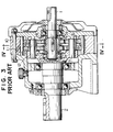
- This planetary reduction gear is of a type in which a rotational force input to an input shaft 1 is transmitted to an output shaft 2 after its rotational speed has been reduced.
- the mechanism for reducing the speed is as described below.
- Eccentric members 31 and 32 are provided on the input shaft 1 at a predetermined phase difference (180° in this embodiment).
- the eccentric members 31 and 32 are respectively in contact with external gears 51 and 52 through bearings 4.
- Each of the external gears 51 and 52 is provided with a plurality of inner roller bores 6, and an inner pin 7 and an inner roller 8 are fitted into each of the bores 6.
- the outer periphery of each of the external gears 51 and 52 is toothed in a trochoidal or arcuate form so as to form trochoidal or arcuate outer teeth 9.
- the outer teeth 9 engage with outer pins 11 provided on an internal gear 10.
- the inner pins 7 are shrink fitted into a flange 12 of the output shaft 2.
- the flange 12 In a case where a power transmission mechanism constituted by the inner roller bores 6, the inner pins 7, and the inner rollers 8 is employed to transmit the rotational force, the flange 12 must be rigid enough to prevent the output shaft 2 from becoming deformed. For this reason, the size of members or portions near the output shaft 2 cannot be reduced in the diametrical direction of the shaft 2.
- This power transmission mechanism requires highly accurate machining, and must also have a suitably high rigidity, since any slight deformation of a member or portion thereof has an adverse effect on the operation.
- the inner roller bores 6 occupy a relatively large space in each of the external gears 51 and 52, and hinder any reduction in the size of the external gears 51 and 52 and, hence, in the size of the overall apparatus.
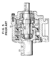
- Fig. 5 shows another known planetary gear mechanism (see the specification of the JP-A-61-38242.
- a carrier 22 is mounted on an external gear 21.
- the carrier 22 is provided with spline grooves 22A
- the output shaft 23 is provided with spline grooves 23A.
- These spline grooves 22A and 23A are coupled by a drive 23 having splines 24A at opposite ends thereof, by which radial load is prevented from acting on the output shaft.
- the external gear 21 of this apparatus has a complicated shape, and it is therefore difficult to machine a large number of external gears 21 which are laid on top of another at one time.
- the external gear 21 and the carrier 22 must be machined in two separate processes.
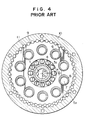
- Fig. 6 shows still another known planetary gear apparatus (see the specification of Japanese Patent Laid-Open No. 60-146939).
- This apparatus is arranged such that an arm-shaped carrier 26 is mounted on an external gear 25, and that the carrier 26 and an output shaft 27 are coupled by a drive 28.
- machining of the external gear 25 is easy.
- a large space for the carrier 26 is required, and the size of the external gear 25 cannot be therefore reduced by a satisfactory degree in the diametrical direction thereof.
- the external gear 25 and the carrier 26 are two separate units, the number of parts is increased, making management of the parts difficult.
- an object of the present invention is to provide a planetary gear apparatus which has a simple structure but is reduced in size as well as in the axial and radial lengths.
- the present invention provides a planetary gear apparatus including the features of the claim.
- an eccentric member 32 is fixed to an input shaft 31, and a ring-shaped external gear 34 is mounted on the eccentric member 32 with a bearing 33 therebetween.
- the axis O2 of the external gear 34 is offset relative to the axis O1 of the input shaft 31 (an internal gear 36) by e.
- the external gear 34 is toothed in a trochoidal or arcuate form so as to form trochoidal or arcuate outer teeth 35.
- the outer teeth 35 engage with the internal gear 36 whose inner teeth are constituted by outer pins 37.
- the external gear 34 is provided with a spline hole 38 which serves as a hole into which the bearing fitted on the eccentric member is inserted and which is coaxial with respect to the outer teeth 35.
- the bearing 33 is directly fitted into the spline hole 38.
- An output shaft 39 is provided with splines 40 which are coaxial with respect to the input shaft 31.
- a floatingly supported drive 41 extends between the spline hole 38 and the splines 40.
- the drive 41 is cylindrical, and has splines 42 fitted into the spline hole 38 at one end thereof as well as spline grooves 43 coupled to the splines 40 at the other end thereof.
- the rotational force input to the input shaft 31 makes the eccentric member 32 rotate, and is then transmitted through the bearing 33 to the external gear 34.
- the axis O1 of the input shaft 31 and the rotational axis O2 of the external gear 34 are shifted by e, and the external gear 34 is coupled to the floatingly supported drive 41.
- the revolution of the external gear 34 about the axis O1 of the input shaft 31 is therefore absorbed by the floating movement of the drive 41, and only the rotation of the input shaft 31 is transmitted to the external gear 34 after its speed has been reduced to a factor which is the reciprocal of the number of outer teeth (if the difference between the number of outer teeth and the number of outer pins is one), because of the engagement of the external gear 34 with the outer pins 37.
- the rotational force of the external gear 34 is then transmitted to the drive 41, and the output shaft 39 is rotated by the drive 41.
- the splines of the output shaft 39 are fitted into the spline grooves formed in the drive 41.
- the splines and spline grooves may be formed on the drive and the output shaft to couple the drive 41 and the output shaft 39.
- the planetary gear apparatus acts as a reduction gear.
- it is clear that it may also be used as a speed-increasing gear, if the input and output shafts are reversed.
- the thus-arranged planetary gear apparatus of the present invention has the following advantages: Since machining errors can be absorbed by the drive that is moved in a floating manner with respect to the external gear and the output shaft, it is not necessary to prepare individual parts with a high degree of accuracy.
- the pitch diameter of the drive can be made larger, and a larger number of outer teeth can be formed. As a result, the load applied to the outer teeth that are in contact with the inner teeth is reduced, and the external gear and the drive therefore need not be subjected to carburization.
- the planetary gear apparatus of the present invention requires no inner roller hole or space for a carrier. Therefore, the size thereof can be reduced in the radial direction as well as in the axial direction.
- the external gear since the external gear has no shoulder for a carrier, it can be easily machined, reducing the production cost thereof.
Landscapes
- Engineering & Computer Science (AREA)
- General Engineering & Computer Science (AREA)
- Mechanical Engineering (AREA)
- Retarders (AREA)
Claims (1)
- Planeten(rad)getriebevorrichtung mit:
einem ringförmigen außenverzahnten Zahnrad (34), das eine Innenbohrung aufweist und über ein in die Innenbohrung eingesetztes Lager (33) auf einem exzentrischen Element (32) einer Antriebswelle (31) befestigt ist,
einem innenverzahnten Rad bzw. Hohlrad (36), das koaxial mit der Antriebswelle (31) ist und mit dem außenverzahnten Zahnrad (34) in Eingriff steht,
einer Abtriebswelle (39), die koaxial mit der Antriebswelle (31) ist und eine verringerte Drehgeschwindigkeit abgibt, und
einem Mitnehmerelement (41), das sich zwischen dem außenverzahnten Zahnrad (34) und der Abtriebswelle (39) erstreckt und an beiden Enden mit dem außenverzahnten Zahnrad (34) bzw. der Abtriebswelle (39) jeweils mittels einer Keilverzahnung bzw. eines Zahnwellenprofils in Eingriff steht,
dadurch gekennzeichnet, daß
die Innenbohrung des außenverzahnten Zahnrads (34) mit einer Keilverzahnung (38) versehen ist, die sich über die gesamte axiale Länge des außenverzahnten Zahnrads (34) erstreckt,
das Lager (33) eine Breite aufweist, die kürzer ist als die Länge der Keilverzahnung (38) und in einen Teil der Innenbohrung auf einer Seite davon eingesetzt ist, und
das Mitnehmerelement (41) am Ende der dem außenverzahnten Zahnrad (34) zugewandten Seite mit einer Keilverzahnung (42) versehen ist, welche mit einem Teil der Zähne bzw. Keilverzahnung (38) auf der anderen Seite der Innenbohrung in Eingriff steht.
Applications Claiming Priority (2)
| Application Number | Priority Date | Filing Date | Title |
|---|---|---|---|
| JP88685/87 | 1987-04-13 | ||
| JP62088685A JPH0627532B2 (ja) | 1987-04-13 | 1987-04-13 | 遊星歯車増減速機 |
Publications (3)
| Publication Number | Publication Date |
|---|---|
| EP0287037A2 EP0287037A2 (de) | 1988-10-19 |
| EP0287037A3 EP0287037A3 (en) | 1990-06-06 |
| EP0287037B1 true EP0287037B1 (de) | 1993-09-01 |
Family
ID=13949691
Family Applications (1)
| Application Number | Title | Priority Date | Filing Date |
|---|---|---|---|
| EP88105822A Expired - Lifetime EP0287037B1 (de) | 1987-04-13 | 1988-04-12 | Planetenradgetriebevorrichtung |
Country Status (5)
| Country | Link |
|---|---|
| US (1) | US4843911A (de) |
| EP (1) | EP0287037B1 (de) |
| JP (1) | JPH0627532B2 (de) |
| KR (1) | KR960015200B1 (de) |
| DE (1) | DE3883579T2 (de) |
Families Citing this family (18)
| Publication number | Priority date | Publication date | Assignee | Title |
|---|---|---|---|---|
| JPH01316144A (ja) * | 1988-03-05 | 1989-12-21 | Teijin Seiki Co Ltd | 自動工具交換装置の駆動装置 |
| JPH02110449U (de) * | 1989-02-21 | 1990-09-04 | ||
| DE69019522T2 (de) * | 1990-09-10 | 1995-10-19 | Sumitomo Heavy Industries | Planetenübersetzungsgetriebe. |
| FR2684154A1 (fr) * | 1991-11-21 | 1993-05-28 | Staubli Sa Ets | Reducteur de vitesse du type cyclouidal pour robots et autres manipulateurs industriels. |
| KR950001733A (ko) * | 1993-06-30 | 1995-01-03 | 배순훈 | 하이퍼 사이클로이드 기어링(Hypo Cycloid Gearing)을 이용한 픽업이송 장치 |
| SE502228C2 (sv) * | 1994-08-12 | 1995-09-18 | Gustav Rennerfelt | Excenterväxel |
| DE19933822A1 (de) * | 1999-07-20 | 2001-02-01 | Zahnradfabrik Friedrichshafen | Leistungsverzweigungsgetriebe |
| TWI223034B (en) * | 2002-08-30 | 2004-11-01 | Sumitomo Heavy Industries | Power transmission device |
| EP1743796A3 (de) * | 2005-07-13 | 2007-03-28 | Kanzaki Kokyukoki MFG. Co., Ltd. | Radantrieb mit Raduntersetzungsgetriebe |
| JP5533096B2 (ja) * | 2010-03-18 | 2014-06-25 | 株式会社リコー | 駆動装置および画像形成装置 |
| JP2012197874A (ja) * | 2011-03-22 | 2012-10-18 | Seiko Epson Corp | 減速機 |
| JP2012197875A (ja) | 2011-03-22 | 2012-10-18 | Seiko Epson Corp | 減速機 |
| EP2860425B1 (de) * | 2012-06-06 | 2019-04-10 | Morihito Nakada | Kraftvervielfältigungslager |
| EP2980447A1 (de) * | 2014-07-28 | 2016-02-03 | Siemens Aktiengesellschaft | Exzentergetriebe oder Exzenterstufe und Antrieb mit Exzentergetriebe oder Exzenterstufe |
| JP6453135B2 (ja) * | 2015-03-27 | 2019-01-16 | 住友重機械工業株式会社 | 偏心揺動型の歯車装置 |
| JP6629175B2 (ja) * | 2016-12-05 | 2020-01-15 | 住友重機械工業株式会社 | 偏心揺動型の歯車装置 |
| JP6803273B2 (ja) * | 2017-03-15 | 2020-12-23 | 株式会社ニッセイ | 差動減速機 |
| FR3160745A1 (fr) * | 2024-03-29 | 2025-10-03 | Valeo Embrayages | Arbre de sortie de couple et dispositif d’actionnement pour système de transmission |
Citations (2)
| Publication number | Priority date | Publication date | Assignee | Title |
|---|---|---|---|---|
| FR2247647A1 (de) * | 1973-10-11 | 1975-05-09 | Hoesch Werke Ag | |
| EP0233303A1 (de) * | 1986-02-19 | 1987-08-26 | Sumitomo Heavy Industries, Ltd | Planetengetriebe |
Family Cites Families (7)
| Publication number | Priority date | Publication date | Assignee | Title |
|---|---|---|---|---|
| GB587607A (en) * | 1944-11-17 | 1947-04-30 | Sidney David Lancaster | Improvements in or relating to electric motors with speed reduction gearing |
| US3405982A (en) * | 1965-12-23 | 1968-10-15 | Fafnir Bearing Co | Self-anchoring bearing |
| DE2358827C2 (de) * | 1973-11-26 | 1975-10-02 | Fa. R. Stahl, 7000 Stuttgart | Getriebeanordnung mit einem Antriebsmotor |
| JPS60146939A (ja) * | 1983-12-31 | 1985-08-02 | Sumitomo Heavy Ind Ltd | 遊星歯車増減速機 |
| JPH0638242A (ja) * | 1992-07-13 | 1994-02-10 | Toshiba Corp | ドロップアウト補償装置 |
| JPH06138242A (ja) * | 1992-10-28 | 1994-05-20 | Murata Mfg Co Ltd | X線検出装置 |
| JPH117940A (ja) * | 1997-06-13 | 1999-01-12 | Aiwa Co Ltd | 電池誤装着検出回路 |
-
1987
- 1987-04-13 JP JP62088685A patent/JPH0627532B2/ja not_active Expired - Fee Related
-
1988
- 1988-04-09 KR KR1019880004012A patent/KR960015200B1/ko not_active Expired - Fee Related
- 1988-04-12 EP EP88105822A patent/EP0287037B1/de not_active Expired - Lifetime
- 1988-04-12 US US07/180,518 patent/US4843911A/en not_active Expired - Lifetime
- 1988-04-12 DE DE88105822T patent/DE3883579T2/de not_active Expired - Fee Related
Patent Citations (2)
| Publication number | Priority date | Publication date | Assignee | Title |
|---|---|---|---|---|
| FR2247647A1 (de) * | 1973-10-11 | 1975-05-09 | Hoesch Werke Ag | |
| EP0233303A1 (de) * | 1986-02-19 | 1987-08-26 | Sumitomo Heavy Industries, Ltd | Planetengetriebe |
Also Published As
| Publication number | Publication date |
|---|---|
| KR890016309A (ko) | 1989-11-28 |
| US4843911A (en) | 1989-07-04 |
| JPH0627532B2 (ja) | 1994-04-13 |
| KR960015200B1 (ko) | 1996-11-01 |
| EP0287037A3 (en) | 1990-06-06 |
| DE3883579D1 (de) | 1993-10-07 |
| DE3883579T2 (de) | 1994-03-10 |
| JPS63254251A (ja) | 1988-10-20 |
| EP0287037A2 (de) | 1988-10-19 |
Similar Documents
| Publication | Publication Date | Title |
|---|---|---|
| EP0287037B1 (de) | Planetenradgetriebevorrichtung | |
| EP0474897B1 (de) | Planetenübersetzungsgetriebe | |
| US4584904A (en) | Epicyclic transmission having free rolling roller driving elements | |
| US5533943A (en) | Planetary gear device including planetary gears each having integrally formed large and small pinions | |
| EP0291052B1 (de) | Planetengetriebesystem | |
| EP0556587B1 (de) | Reihe drehzahlsteigernder und -senkender Getriebe unter Verwendung einer Getriebekonstruktion nach dem Zykloidenprinzip | |
| EP0548888B1 (de) | Zykloidengetriebe | |
| EP0130033B1 (de) | Spannungswellen-Erzeuger mit Doppelexzenter | |
| US3424036A (en) | Speed changing device | |
| US4770062A (en) | Planetary gear apparatus | |
| EP1210532A1 (de) | Planetengetriebe mit lastausgleich | |
| US6179743B1 (en) | Gearing for power sharing in planetary transmission | |
| US11788606B2 (en) | Transmission mechanism | |
| US6436000B1 (en) | Shaft coupling structure with speed change function | |
| EP2730805B1 (de) | Untersetzungsgetriebe | |
| JP2743285B2 (ja) | 遊星歯車増減速装置 | |
| US5255895A (en) | Gear transmission in a lifting machinery | |
| JP2739909B2 (ja) | 遊星歯車減速機 | |
| JPH04290643A (ja) | トロコイド系歯形内接式遊星歯車構造 | |
| CA1317126C (en) | Gear transmission for lifting machine | |
| JPH0571819B2 (de) | ||
| JPH0627867Y2 (ja) | 遊星歯車増減速機における出力軸の連結装置 | |
| JPS6138242A (ja) | 遊星歯車増減速機 | |
| JP4450903B2 (ja) | 単純遊星ローラユニットの連結構造 | |
| JPH03260436A (ja) | 内接噛合遊星歯車構造 |
Legal Events
| Date | Code | Title | Description |
|---|---|---|---|
| PUAI | Public reference made under article 153(3) epc to a published international application that has entered the european phase |
Free format text: ORIGINAL CODE: 0009012 |
|
| AK | Designated contracting states |
Kind code of ref document: A2 Designated state(s): AT BE CH DE ES FR GB GR IT LI LU NL SE |
|
| RIN1 | Information on inventor provided before grant (corrected) |
Inventor name: ISHIDA, TOSHIHIRO Inventor name: MINEGISHI, KIYOJI |
|
| PUAL | Search report despatched |
Free format text: ORIGINAL CODE: 0009013 |
|
| AK | Designated contracting states |
Kind code of ref document: A3 Designated state(s): AT BE CH DE ES FR GB GR IT LI LU NL SE |
|
| 17P | Request for examination filed |
Effective date: 19901109 |
|
| 17Q | First examination report despatched |
Effective date: 19920427 |
|
| RBV | Designated contracting states (corrected) |
Designated state(s): DE FR GB IT |
|
| GRAA | (expected) grant |
Free format text: ORIGINAL CODE: 0009210 |
|
| AK | Designated contracting states |
Kind code of ref document: B1 Designated state(s): DE FR GB IT |
|
| ITF | It: translation for a ep patent filed | ||
| REF | Corresponds to: |
Ref document number: 3883579 Country of ref document: DE Date of ref document: 19931007 |
|
| ET | Fr: translation filed | ||
| PLBE | No opposition filed within time limit |
Free format text: ORIGINAL CODE: 0009261 |
|
| STAA | Information on the status of an ep patent application or granted ep patent |
Free format text: STATUS: NO OPPOSITION FILED WITHIN TIME LIMIT |
|
| 26N | No opposition filed | ||
| PGFP | Annual fee paid to national office [announced via postgrant information from national office to epo] |
Ref country code: DE Payment date: 20010402 Year of fee payment: 14 |
|
| PGFP | Annual fee paid to national office [announced via postgrant information from national office to epo] |
Ref country code: FR Payment date: 20010409 Year of fee payment: 14 |
|
| PGFP | Annual fee paid to national office [announced via postgrant information from national office to epo] |
Ref country code: GB Payment date: 20010411 Year of fee payment: 14 |
|
| REG | Reference to a national code |
Ref country code: GB Ref legal event code: IF02 |
|
| PG25 | Lapsed in a contracting state [announced via postgrant information from national office to epo] |
Ref country code: GB Free format text: LAPSE BECAUSE OF NON-PAYMENT OF DUE FEES Effective date: 20020412 |
|
| PG25 | Lapsed in a contracting state [announced via postgrant information from national office to epo] |
Ref country code: DE Free format text: LAPSE BECAUSE OF NON-PAYMENT OF DUE FEES Effective date: 20021101 |
|
| GBPC | Gb: european patent ceased through non-payment of renewal fee |
Effective date: 20020412 |
|
| PG25 | Lapsed in a contracting state [announced via postgrant information from national office to epo] |
Ref country code: FR Free format text: LAPSE BECAUSE OF NON-PAYMENT OF DUE FEES Effective date: 20021231 |
|
| REG | Reference to a national code |
Ref country code: FR Ref legal event code: ST |
|
| PG25 | Lapsed in a contracting state [announced via postgrant information from national office to epo] |
Ref country code: IT Free format text: LAPSE BECAUSE OF NON-PAYMENT OF DUE FEES;WARNING: LAPSES OF ITALIAN PATENTS WITH EFFECTIVE DATE BEFORE 2007 MAY HAVE OCCURRED AT ANY TIME BEFORE 2007. THE CORRECT EFFECTIVE DATE MAY BE DIFFERENT FROM THE ONE RECORDED. Effective date: 20050412 |