EP2860425B1 - Kraftvervielfältigungslager - Google Patents
Kraftvervielfältigungslager Download PDFInfo
- Publication number
- EP2860425B1 EP2860425B1 EP12871604.0A EP12871604A EP2860425B1 EP 2860425 B1 EP2860425 B1 EP 2860425B1 EP 12871604 A EP12871604 A EP 12871604A EP 2860425 B1 EP2860425 B1 EP 2860425B1
- Authority
- EP
- European Patent Office
- Prior art keywords
- levers
- ring
- force
- inner ring
- outer ring
- Prior art date
- Legal status (The legal status is an assumption and is not a legal conclusion. Google has not performed a legal analysis and makes no representation as to the accuracy of the status listed.)
- Not-in-force
Links
Images


Classifications
-
- F—MECHANICAL ENGINEERING; LIGHTING; HEATING; WEAPONS; BLASTING
- F16—ENGINEERING ELEMENTS AND UNITS; GENERAL MEASURES FOR PRODUCING AND MAINTAINING EFFECTIVE FUNCTIONING OF MACHINES OR INSTALLATIONS; THERMAL INSULATION IN GENERAL
- F16C—SHAFTS; FLEXIBLE SHAFTS; ELEMENTS OR CRANKSHAFT MECHANISMS; ROTARY BODIES OTHER THAN GEARING ELEMENTS; BEARINGS
- F16C19/00—Bearings with rolling contact, for exclusively rotary movement
- F16C19/54—Systems consisting of a plurality of bearings with rolling friction
- F16C19/55—Systems consisting of a plurality of bearings with rolling friction with intermediate floating or independently-driven rings rotating at reduced speed or with other differential ball or roller bearings
-
- F—MECHANICAL ENGINEERING; LIGHTING; HEATING; WEAPONS; BLASTING
- F16—ENGINEERING ELEMENTS AND UNITS; GENERAL MEASURES FOR PRODUCING AND MAINTAINING EFFECTIVE FUNCTIONING OF MACHINES OR INSTALLATIONS; THERMAL INSULATION IN GENERAL
- F16H—GEARING
- F16H25/00—Gearings comprising primarily only cams, cam-followers and screw-and-nut mechanisms
- F16H25/04—Gearings comprising primarily only cams, cam-followers and screw-and-nut mechanisms for conveying rotary motion
- F16H25/06—Gearings comprising primarily only cams, cam-followers and screw-and-nut mechanisms for conveying rotary motion with intermediate members guided along tracks on both rotary members
Definitions
- the present invention relates to an incremented force bearing for use in doubling a force applied to wheels of aircrafts, electric cars, bicycles for aged person or disabled person, or the like, or for use in an auxiliary power of a wind generator, etc.
- a conventional bearing supports rotators relative to an axle, and it is divided broadly into a radial bearing and a thrust bearing, of which the radial bearing comprises an inner ring in which the axle is engaged, an outer ring disposed outside the inner ring, and many bearings interposed between the inner and outer rings, wherein respective bearings (rotators) are housed in a ring-shaped retainer.
- a rotational friction between the inner ring and the outer ring is exceedingly small and there is no resistance therebetween so that rotators can be pivotally mounted on the axle to be smoothly rotated relative to the axle.
- an incremented force mechanism is separately needed so that a force that is larger than an applied force can rotate the rotators.
- a derailleur can serve as an incremented force mechanism.
- the derailleur can be made up of a chain, but the derailleur can not be mounted on the same axle. Accordingly, it was not possible to provide an incremented force mechanism on a wheelchair wherein a hand-operated wheel and wheels of the wheelchair are provided on the same axle.
- a multiplication mechanism is provided on a wheelchair, it becomes a very complicated mechanism, and hence it becomes impossible in a practical sense, which causes the disabled person very hardship even if the wheelchair gets over a slight slant.
- the electric car requires an electric power more than a current output when driving on an upslope and it is absolutely uncompetitive compared with a gasoline-powered car.
- an object of the present invention to provide an incremented force bearing for outputting a rotative force applied to the outer ring to the inner ring as a doubled force, and means for generating a doubled force can be provided on the same axle, thereby providing an incremented force mechanism, wherein a mechanism for obtaining a doubled force is simplified.
- the present invention solves the foregoing problems and provides an incremented force bearing according to claim 1.
- the incremented force bearing has been configured as set forth above, when the outer ring 1 is rotated, the wavy slide surface 14 formed on the outer ring 1 is simultaneously rotated, so that the levers 9 pivotally mounted on the inner ring 2 are rotated while pressed by the wavy slide surface 14 at the end thereof so that the levers 9 press the wavy slide surface 15 of the inner ring 2, causing crest parts 15b of the wavy slide surface 15 of the inner ring 2 to be sequentially forwarded to rotate the inner ring 2.
- the waveform pitch is wider in the outer ring 1 so as to have much workload, a doubled force rotates the inner ring 2.
- the rotative force applied to the outer ring 1 is outputted to the inner ring 2 as a doubled force so that if rotators 5 are fitted to the inner ring 1, the rotation of the outer ring 1 can strongly work on the rotators 5, and means for working the rotation on the rotators 5 is a bearing mechanism to be mounted on the same axle, thereby achieving an excellent effect to incredibly simplify the mechanism for obtaining a doubled force of the rotation when used in various machines, vehicle bodies, equipments, etc.
- the incremented force bearing of the present invention is applied to wheels of an aircraft, when the aircraft runs on a taxiway through a runway, a lot of fuel consumption is saved. If the incremented force bearing is incorporated into a derailleur a bicycle for hill climbing or a derailleur of a bicycle for racing, it can assist an operator. Further if the incremented force bearing is applied to auxiliary wheels of the wheel chair, it is possible to obtain strong hill-climbing ability in a sloping road, etc. Further, if the incremented force bearing is applied to a wind generator, it exhibits an excellent effect as an auxiliary power when a wind power is weakened.
- the incremented force bearing of the present invention comprises a bearing substrate made up of an inner ring 2, an outer ring 1 and one or more intermediate rings 3, 3a, 3b interposed between the inner ring 2 and the outer ring 1.
- the shapes of rotators 5 interposed between the inner ring 2, outer ring 1, and intermediate ring 3 are various. Further, a plurality of levers 9 are used for transmitting a power from the outer ring 1 to the inner ring 2.
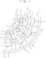
- Figs. 1 to 3 show a first embodiment of the present invention, wherein the incremented force bearing of the present invention comprises an inner ring 2, an outer ring 1 and an intermediate ring 3 interposed between the inner ring 2 and the outer ring 1, forming a disc-shaped substrate, wherein rotators 5, 5... are interposed between the intermediate ring 3 and the outer ring 1 and between the intermediate ring 3 and the inner ring 2 so that the inner ring 2 and the outer ring 1 can be rotated independently from each other.
- the rotators 5, 5... are columnar and each rotator 5 is provided with a role 7 at the central part thereof.
- a plurality of levers 9, 9... are arranged radially on the upper surface of the substrate and they are in the form of plates and are held on the intermediate ring 3 by check pins 10 to be horizontally rotated.
- annulus recess 12 having a lower upper surface under which the intermediate ring 3 is formed and a lower upper surface formed by recessing a part of the intermediate ring 2 and a part of the outer ring at both sides of the intermediate ring 3.
- Recessed side surfaces of the annulus recess 12 are formed on both the inner ring 2 and the outer ring 1, and they are formed in a wavelike fashion as wavy slide surfaces 14, 15 which both ends of the levers 9, 9... enter into or leave from.
- the wavy slide surfaces 14, 15 have wavy crest parts 14a, 15a and valley parts 14b, 15b, and these parts 14b, 15b are positioned in the same direction but pitches of these parts 14b, 15b at the outer ring side are several times as large as these parts 14b, 15b at the inner ring 1 side. Meanwhile, a gear tooth 17 is formed on the outer periphery of the outer ring 1.
- each lever 9 is formed wider and another half part is formed gradually narrower toward the inner side thereof.
- Each lever 9 has one end formed of a wider arc end edge 9a and another end formed of a narrower arc end edge 9b, which are respectively joined the wavy slide surfaces 14 and 15.
- the wider arc end edge 9a and the narrower arc end edge 9b are respectively recessed in the valleys 14b, 15b ( FIG. 1 ).
- a pair of retaining springs 13, 13 for clamping the narrowing end parts of the levers 9, 9... are provided for respective levers 9, 9....
- the retaining springs 13, 13 are bent in an L-shape and is held on the side surface of the intermediate ring 3. Since both the retaining springs 13, 13 clamp the levers 9, 9... elastically at the inclined edge portions which are gradually narrower toward the tip end, when the levers 9, 9... move, the levers 9, 9... are liable to obtain a return force to secondarily move toward the wider arc end edge 9a.
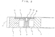
- Figs. 4 and 5 represent a second embodiment, wherein a bearing substrate comprises an inner ring 2, an outer ring 1, two intermediate rings 3a and 3b, and rotators 5, 5... (omitted in Fig. 4 ) which are interposed therebetween so that the inner ring 2 and the outer ring 1 can be freely rotated via the intermediate rings 3a, 3b.
- An annular recess 12 is formed on the upper surface of the bearing surface and wavy slide surfaces 14, 15 are formed on the outer ring 1 and the inner ring 2 as the edges of the annulus recess 12.
- a main lever 21 joining the wavy slide surface 14 of the outer ring 1, and an auxiliary lever 23 joining the slide surface 15 of the inner ring 2 are provided separately, and a plurality of levers 25, 26, 27, 28 are interposed between the main lever 21 and the auxiliary lever 23 to constitute a doubled force link mechanism 20.
- Depicted by 30 are connection pins of the levers 25 to 28 and the main lever 21 is indirectly held by a check pin 10 via the dependent lever 25.
- Depicted by 32 is a central bearing pin of the doubled force link mechanism 20.
- FIG. 4 a doubled force of the doubled force link mechanism 20 is explained.
- the lengths of the levers about the check pin 10 serving as a fulcrum are a, b, a formula a > b is established, it represents that when the main lever 21 receive a force Fkg from the slide surface 14 at the wide wider arc end edge 9a, the narrower arc end edge 9b... exerts a force of a F(a/b) 2 kg on the slide surface 15.
- the incremented force becomes F(a/b) 2
- the incremented force becomes F(a/b) 3
- the incremented force becomes F(a/b) 4
- the incremented force becomes F(a/b) n .
Claims (3)
- Krafterhöhungslager, umfassend ein Lagersubstrat, das aus mehreren Ringen gebildet ist, umfassend einen Innenring (2), einen Außenring (1) und einen Zwischenring (3; 3a, 3b), der zwischen dem Innenring und dem Außenring (2, 2) angeordnet ist, wobei Rotatoren (5) zwischen jeweiligen Außen-, Innen- und Zwischenringen (2, 1, 3; 3a, 3b) angeordnet sind, so dass der Innenring (2) und der Außenring (1) gegeneinander gedreht werden können, wobei eine ringförmige Ausnehmung (12) auf der oberen Oberfläche des Lagersubstrats vorgesehen und in dieser ausgespart ist, wobei Hebel (9) in einer Reihe um eine Mitte der oberen Oberfläche des Lagersubstrats angeordnet sind, wobei die ringförmige Aussparung (12) wellenförmige Gleitflächen als ausgesparte Flächen aufweist, durch die die Hebel (9) an den Innen- und Außenring (2, 1) gedrückt werden, wobei die Anordnung der Hebel (9) derart ist, dass die Hebel an die Gleitfläche (14) des äußeren Rings (1) anschließen und schwenkbar an dem Zwischenring (3; 3a, 3b) gelagert sind, dadurch gekennzeichnet, dass ein Wellenformabstand des Außenrings (1) breiter als der des Innenrings (2) ist, und dass aufgrund der Anordnung dieser Hebel (9) eine Druckkraft, die durch eine wellenförmige Verbindung zwischen dem Außenring (1) und den Hebeln (9) bei der Aufnahme von der wellenförmigen Gleitfläche (14) des äußeren Ringes (1) erzeugt wird, auf die wellenförmige Gleitfläche (15) des inneren Ringes (2) über einen oder mehrere Hebel (9) drückt, wodurch Scheitelteile (15b) der wellenförmigen Oberfläche (15) des Innenrings (2) dazu veranlasst werden, nacheinander vorwärts bewegt zu werden, um den Innenring (2) zu drehen.
- Krafterhöhungslager nach Anspruch 1, dadurch gekennzeichnet, dass die Hebel (9) derart angeordnet sind, dass die jeweiligen in Umfangsrichtung angeordneten Hebel (9) durch einen Prüfstift (3, 3a, 3b) schwenkbar am Zwischenring (3; 3a, 3b) angebracht sind, wobei ein Ende der Hebel (9) die Gleitfläche (14) des Außenrings (1) berührt und das andere Ende der Hebel (9) die Gleitfläche (15) des Innenrings (2) berührt.
- Krafterhöhungslager nach Anspruch 1, wobei die Hebel (9) derart angeordnet sind, dass ein Krafterhöhungslagerverbindungsmechanismus (20) zum Verbinden eines Haupthebels (21) und eines Hilfshebels (23) zwischen dem Haupthebel (21), der die Gleitfläche (14) des Außenrings (1) kontaktiert, und dem Hilfshebel (23), der die Gleitfläche (15) des Innenrings (2) kontaktiert, gebildet ist.
Applications Claiming Priority (1)
| Application Number | Priority Date | Filing Date | Title |
|---|---|---|---|
| PCT/JP2012/064520 WO2013183124A1 (ja) | 2012-06-06 | 2012-06-06 | 増力軸受 |
Publications (3)
| Publication Number | Publication Date |
|---|---|
| EP2860425A1 EP2860425A1 (de) | 2015-04-15 |
| EP2860425A4 EP2860425A4 (de) | 2016-10-12 |
| EP2860425B1 true EP2860425B1 (de) | 2019-04-10 |
Family
ID=49711541
Family Applications (1)
| Application Number | Title | Priority Date | Filing Date |
|---|---|---|---|
| EP12871604.0A Not-in-force EP2860425B1 (de) | 2012-06-06 | 2012-06-06 | Kraftvervielfältigungslager |
Country Status (5)
| Country | Link |
|---|---|
| US (1) | US9074623B2 (de) |
| EP (1) | EP2860425B1 (de) |
| KR (1) | KR101587552B1 (de) |
| CN (1) | CN103608609B (de) |
| WO (1) | WO2013183124A1 (de) |
Families Citing this family (5)
| Publication number | Priority date | Publication date | Assignee | Title |
|---|---|---|---|---|
| US10428916B2 (en) | 2013-03-12 | 2019-10-01 | Motus Labs, LLC | Spiral cam gearbox mechanism |
| US11015685B2 (en) | 2013-03-12 | 2021-05-25 | Motus Labs, LLC | Axial cam gearbox mechanism |
| US10626964B2 (en) | 2013-03-12 | 2020-04-21 | Motus Labs, LLC | Axial cam gearbox mechanism |
| US10151375B2 (en) | 2013-03-12 | 2018-12-11 | Motus Labs, LLC | Motorized gearbox mechanism |
| WO2020040793A1 (en) * | 2018-08-24 | 2020-02-27 | Motus Labs, LLC | Simplified gearbox mechanism |
Family Cites Families (23)
| Publication number | Priority date | Publication date | Assignee | Title |
|---|---|---|---|---|
| GB191117592A (en) * | 1911-08-02 | 1912-03-14 | Paul Leistriz | Improvements in or relating to Speed Multiplying or Reducing or Varying Gearing. |
| US3468175A (en) * | 1967-08-15 | 1969-09-23 | Jan W Rabek | Transmission |
| JPS51136079A (en) | 1975-05-17 | 1976-11-25 | Shunjiro Asao | Speed reduction device |
| IT1072586B (it) | 1976-09-30 | 1985-04-10 | Gamba Vittorio | Convertitore di coppia di tipo meccanica |
| JPS548050A (en) | 1977-06-17 | 1979-01-22 | Sharp Kk | Device of selecting pattern of sewing machine |
| JPS548050U (de) * | 1977-06-18 | 1979-01-19 | ||
| JPS60256643A (ja) * | 1984-05-31 | 1985-12-18 | Moritomo Ando | 減速装置 |
| CN85200923U (zh) * | 1985-04-01 | 1986-02-12 | 湖北省机械研究所 | 传动轴承 |
| EP0201730B1 (de) * | 1985-04-12 | 1989-12-27 | Beijing Institute of Aeronautics and Astronautics | Exzentergetriebe mit oszillierenden Zähnen |
| US4618271A (en) * | 1985-12-11 | 1986-10-21 | Florida State University | Serial bearing assembly |
| JPH0627532B2 (ja) * | 1987-04-13 | 1994-04-13 | 住友重機械工業株式会社 | 遊星歯車増減速機 |
| US4838741A (en) * | 1987-05-01 | 1989-06-13 | Primaxis Corporation | Method for making an epicyclic speed reducer with two stage integral rotor |
| JPH02266148A (ja) * | 1989-04-06 | 1990-10-30 | Ryuichi Sato | 動力増大機 |
| JP3278469B2 (ja) * | 1992-08-25 | 2002-04-30 | 高砂熱学工業株式会社 | 歯車式無段変速機 |
| US5431605A (en) * | 1993-11-30 | 1995-07-11 | Ko; Chung C. | Speed reducer which employs rolling means |
| CN1166577A (zh) * | 1995-06-04 | 1997-12-03 | 叶齐萌 | 非圆弧面变速轴承 |
| JPH10267048A (ja) * | 1997-03-25 | 1998-10-06 | Sanden Corp | 動力伝達機構 |
| US6416438B1 (en) | 1999-04-30 | 2002-07-09 | ByongChol Choi | Transmitting unit |
| KR200208549Y1 (ko) | 1999-04-30 | 2001-01-15 | 최병철 | 동력 전달 장치 |
| US6314826B1 (en) * | 1999-10-29 | 2001-11-13 | Synkinetics, Inc. | Nested speed converter bearing apparatus |
| DE10247204B4 (de) * | 2002-10-10 | 2004-12-16 | Jan Klindworth | Verstellvorrichtung |
| BE1016493A3 (nl) | 2005-04-13 | 2006-12-05 | Wiele Michel Van De Nv | Inrichting voor het moduleren van een eerste roterende beweging van een inkomende as naar een tweede, verschillend van de eerste, roterende beweging van een uitgaande as bij textielmachines. |
| DE102007058605B4 (de) * | 2007-12-04 | 2014-06-18 | Wittenstein Ag | Antriebseinheit für die Antriebstechnik mit hoher Leistungsdichte mit zumindest einer Übersetzungsstufe |
-
2012
- 2012-06-06 US US14/007,550 patent/US9074623B2/en not_active Expired - Fee Related
- 2012-06-06 KR KR1020147006390A patent/KR101587552B1/ko active IP Right Grant
- 2012-06-06 CN CN201280014647.9A patent/CN103608609B/zh not_active Expired - Fee Related
- 2012-06-06 EP EP12871604.0A patent/EP2860425B1/de not_active Not-in-force
- 2012-06-06 WO PCT/JP2012/064520 patent/WO2013183124A1/ja active Application Filing
Non-Patent Citations (1)
| Title |
|---|
| None * |
Also Published As
| Publication number | Publication date |
|---|---|
| KR101587552B1 (ko) | 2016-01-21 |
| US20140248017A1 (en) | 2014-09-04 |
| EP2860425A4 (de) | 2016-10-12 |
| US9074623B2 (en) | 2015-07-07 |
| CN103608609B (zh) | 2016-03-16 |
| EP2860425A1 (de) | 2015-04-15 |
| WO2013183124A1 (ja) | 2013-12-12 |
| KR20140085422A (ko) | 2014-07-07 |
| CN103608609A (zh) | 2014-02-26 |
Similar Documents
| Publication | Publication Date | Title |
|---|---|---|
| EP2860425B1 (de) | Kraftvervielfältigungslager | |
| JP2019537019A5 (de) | ||
| EP3479960A1 (de) | Nicht in vorwärtsrichtung einrastender mechanismus zur verhinderung von richtungswechsel | |
| US20170274963A1 (en) | Drive unit for bicycle | |
| US9599174B2 (en) | Brake device | |
| JP2016516633A5 (de) | ||
| KR101849187B1 (ko) | 파동기어장치의 파동발생기 및 파동발생기의 제조방법 | |
| TWI615564B (zh) | 摩擦式無級變速器 | |
| CN207315899U (zh) | 离合器控制机构及其应用的内变速器 | |
| TW201331073A (zh) | 附剎車碟片的鐵道車輪組裝裝置 | |
| US10576645B2 (en) | Fastener, splicing piece and fastener connecting member | |
| US20210180654A1 (en) | Transmission | |
| US9909655B2 (en) | Mechanically operational structure for continuously variable transmission | |
| JP2008232164A (ja) | 無段変速機及び無段変速機付き自転車 | |
| CN104019201A (zh) | 无级变速器 | |
| CN107664164A (zh) | 具有由不同材料制成的部件的多件式背板 | |
| US3800608A (en) | Variable diameter v-belt pulley assembly | |
| JPWO2016024300A1 (ja) | 駆動ユニットおよび電動アシスト自転車 | |
| JP5767270B2 (ja) | 操舵可能な駆動伝達装置 | |
| US10641381B2 (en) | Gear assembly | |
| JP2016031075A (ja) | ホイールイン減速装置およびホイールユニット | |
| RU2532322C1 (ru) | Движитель транспортного средства | |
| JP2012237372A (ja) | 増力軸受 | |
| JP5978795B2 (ja) | 動力伝達チェーンの組立治具および製造装置 | |
| CN103836128A (zh) | 电动车三挡变速传动机构 |
Legal Events
| Date | Code | Title | Description |
|---|---|---|---|
| PUAI | Public reference made under article 153(3) epc to a published international application that has entered the european phase |
Free format text: ORIGINAL CODE: 0009012 |
|
| 17P | Request for examination filed |
Effective date: 20130925 |
|
| AK | Designated contracting states |
Kind code of ref document: A1 Designated state(s): AL AT BE BG CH CY CZ DE DK EE ES FI FR GB GR HR HU IE IS IT LI LT LU LV MC MK MT NL NO PL PT RO RS SE SI SK SM TR |
|
| AX | Request for extension of the european patent |
Extension state: BA ME |
|
| DAX | Request for extension of the european patent (deleted) | ||
| RA4 | Supplementary search report drawn up and despatched (corrected) |
Effective date: 20160913 |
|
| RIC1 | Information provided on ipc code assigned before grant |
Ipc: F16H 35/00 20060101AFI20160907BHEP |
|
| GRAP | Despatch of communication of intention to grant a patent |
Free format text: ORIGINAL CODE: EPIDOSNIGR1 |
|
| STAA | Information on the status of an ep patent application or granted ep patent |
Free format text: STATUS: GRANT OF PATENT IS INTENDED |
|
| INTG | Intention to grant announced |
Effective date: 20181203 |
|
| GRAS | Grant fee paid |
Free format text: ORIGINAL CODE: EPIDOSNIGR3 |
|
| GRAA | (expected) grant |
Free format text: ORIGINAL CODE: 0009210 |
|
| STAA | Information on the status of an ep patent application or granted ep patent |
Free format text: STATUS: THE PATENT HAS BEEN GRANTED |
|
| AK | Designated contracting states |
Kind code of ref document: B1 Designated state(s): AL AT BE BG CH CY CZ DE DK EE ES FI FR GB GR HR HU IE IS IT LI LT LU LV MC MK MT NL NO PL PT RO RS SE SI SK SM TR |
|
| REG | Reference to a national code |
Ref country code: GB Ref legal event code: FG4D |
|
| REG | Reference to a national code |
Ref country code: CH Ref legal event code: EP Ref country code: AT Ref legal event code: REF Ref document number: 1119101 Country of ref document: AT Kind code of ref document: T Effective date: 20190415 |
|
| REG | Reference to a national code |
Ref country code: IE Ref legal event code: FG4D |
|
| REG | Reference to a national code |
Ref country code: DE Ref legal event code: R096 Ref document number: 602012058961 Country of ref document: DE |
|
| REG | Reference to a national code |
Ref country code: NL Ref legal event code: MP Effective date: 20190410 |
|
| REG | Reference to a national code |
Ref country code: LT Ref legal event code: MG4D |
|
| REG | Reference to a national code |
Ref country code: AT Ref legal event code: MK05 Ref document number: 1119101 Country of ref document: AT Kind code of ref document: T Effective date: 20190410 |
|
| PG25 | Lapsed in a contracting state [announced via postgrant information from national office to epo] |
Ref country code: NL Free format text: LAPSE BECAUSE OF FAILURE TO SUBMIT A TRANSLATION OF THE DESCRIPTION OR TO PAY THE FEE WITHIN THE PRESCRIBED TIME-LIMIT Effective date: 20190410 |
|
| PG25 | Lapsed in a contracting state [announced via postgrant information from national office to epo] |
Ref country code: FI Free format text: LAPSE BECAUSE OF FAILURE TO SUBMIT A TRANSLATION OF THE DESCRIPTION OR TO PAY THE FEE WITHIN THE PRESCRIBED TIME-LIMIT Effective date: 20190410 Ref country code: AL Free format text: LAPSE BECAUSE OF FAILURE TO SUBMIT A TRANSLATION OF THE DESCRIPTION OR TO PAY THE FEE WITHIN THE PRESCRIBED TIME-LIMIT Effective date: 20190410 Ref country code: SE Free format text: LAPSE BECAUSE OF FAILURE TO SUBMIT A TRANSLATION OF THE DESCRIPTION OR TO PAY THE FEE WITHIN THE PRESCRIBED TIME-LIMIT Effective date: 20190410 Ref country code: PT Free format text: LAPSE BECAUSE OF FAILURE TO SUBMIT A TRANSLATION OF THE DESCRIPTION OR TO PAY THE FEE WITHIN THE PRESCRIBED TIME-LIMIT Effective date: 20190910 Ref country code: NO Free format text: LAPSE BECAUSE OF FAILURE TO SUBMIT A TRANSLATION OF THE DESCRIPTION OR TO PAY THE FEE WITHIN THE PRESCRIBED TIME-LIMIT Effective date: 20190710 Ref country code: HR Free format text: LAPSE BECAUSE OF FAILURE TO SUBMIT A TRANSLATION OF THE DESCRIPTION OR TO PAY THE FEE WITHIN THE PRESCRIBED TIME-LIMIT Effective date: 20190410 Ref country code: LT Free format text: LAPSE BECAUSE OF FAILURE TO SUBMIT A TRANSLATION OF THE DESCRIPTION OR TO PAY THE FEE WITHIN THE PRESCRIBED TIME-LIMIT Effective date: 20190410 Ref country code: ES Free format text: LAPSE BECAUSE OF FAILURE TO SUBMIT A TRANSLATION OF THE DESCRIPTION OR TO PAY THE FEE WITHIN THE PRESCRIBED TIME-LIMIT Effective date: 20190410 |
|
| PG25 | Lapsed in a contracting state [announced via postgrant information from national office to epo] |
Ref country code: LV Free format text: LAPSE BECAUSE OF FAILURE TO SUBMIT A TRANSLATION OF THE DESCRIPTION OR TO PAY THE FEE WITHIN THE PRESCRIBED TIME-LIMIT Effective date: 20190410 Ref country code: RS Free format text: LAPSE BECAUSE OF FAILURE TO SUBMIT A TRANSLATION OF THE DESCRIPTION OR TO PAY THE FEE WITHIN THE PRESCRIBED TIME-LIMIT Effective date: 20190410 Ref country code: BG Free format text: LAPSE BECAUSE OF FAILURE TO SUBMIT A TRANSLATION OF THE DESCRIPTION OR TO PAY THE FEE WITHIN THE PRESCRIBED TIME-LIMIT Effective date: 20190710 Ref country code: GR Free format text: LAPSE BECAUSE OF FAILURE TO SUBMIT A TRANSLATION OF THE DESCRIPTION OR TO PAY THE FEE WITHIN THE PRESCRIBED TIME-LIMIT Effective date: 20190711 Ref country code: PL Free format text: LAPSE BECAUSE OF FAILURE TO SUBMIT A TRANSLATION OF THE DESCRIPTION OR TO PAY THE FEE WITHIN THE PRESCRIBED TIME-LIMIT Effective date: 20190410 |
|
| PG25 | Lapsed in a contracting state [announced via postgrant information from national office to epo] |
Ref country code: IS Free format text: LAPSE BECAUSE OF FAILURE TO SUBMIT A TRANSLATION OF THE DESCRIPTION OR TO PAY THE FEE WITHIN THE PRESCRIBED TIME-LIMIT Effective date: 20190810 Ref country code: AT Free format text: LAPSE BECAUSE OF FAILURE TO SUBMIT A TRANSLATION OF THE DESCRIPTION OR TO PAY THE FEE WITHIN THE PRESCRIBED TIME-LIMIT Effective date: 20190410 |
|
| REG | Reference to a national code |
Ref country code: DE Ref legal event code: R097 Ref document number: 602012058961 Country of ref document: DE |
|
| PG25 | Lapsed in a contracting state [announced via postgrant information from national office to epo] |
Ref country code: MC Free format text: LAPSE BECAUSE OF FAILURE TO SUBMIT A TRANSLATION OF THE DESCRIPTION OR TO PAY THE FEE WITHIN THE PRESCRIBED TIME-LIMIT Effective date: 20190410 Ref country code: SK Free format text: LAPSE BECAUSE OF FAILURE TO SUBMIT A TRANSLATION OF THE DESCRIPTION OR TO PAY THE FEE WITHIN THE PRESCRIBED TIME-LIMIT Effective date: 20190410 Ref country code: DK Free format text: LAPSE BECAUSE OF FAILURE TO SUBMIT A TRANSLATION OF THE DESCRIPTION OR TO PAY THE FEE WITHIN THE PRESCRIBED TIME-LIMIT Effective date: 20190410 Ref country code: EE Free format text: LAPSE BECAUSE OF FAILURE TO SUBMIT A TRANSLATION OF THE DESCRIPTION OR TO PAY THE FEE WITHIN THE PRESCRIBED TIME-LIMIT Effective date: 20190410 Ref country code: RO Free format text: LAPSE BECAUSE OF FAILURE TO SUBMIT A TRANSLATION OF THE DESCRIPTION OR TO PAY THE FEE WITHIN THE PRESCRIBED TIME-LIMIT Effective date: 20190410 Ref country code: CZ Free format text: LAPSE BECAUSE OF FAILURE TO SUBMIT A TRANSLATION OF THE DESCRIPTION OR TO PAY THE FEE WITHIN THE PRESCRIBED TIME-LIMIT Effective date: 20190410 |
|
| REG | Reference to a national code |
Ref country code: CH Ref legal event code: PL |
|
| PLBE | No opposition filed within time limit |
Free format text: ORIGINAL CODE: 0009261 |
|
| STAA | Information on the status of an ep patent application or granted ep patent |
Free format text: STATUS: NO OPPOSITION FILED WITHIN TIME LIMIT |
|
| PG25 | Lapsed in a contracting state [announced via postgrant information from national office to epo] |
Ref country code: SM Free format text: LAPSE BECAUSE OF FAILURE TO SUBMIT A TRANSLATION OF THE DESCRIPTION OR TO PAY THE FEE WITHIN THE PRESCRIBED TIME-LIMIT Effective date: 20190410 Ref country code: IT Free format text: LAPSE BECAUSE OF FAILURE TO SUBMIT A TRANSLATION OF THE DESCRIPTION OR TO PAY THE FEE WITHIN THE PRESCRIBED TIME-LIMIT Effective date: 20190410 |
|
| 26N | No opposition filed |
Effective date: 20200113 |
|
| REG | Reference to a national code |
Ref country code: BE Ref legal event code: MM Effective date: 20190630 |
|
| PG25 | Lapsed in a contracting state [announced via postgrant information from national office to epo] |
Ref country code: TR Free format text: LAPSE BECAUSE OF FAILURE TO SUBMIT A TRANSLATION OF THE DESCRIPTION OR TO PAY THE FEE WITHIN THE PRESCRIBED TIME-LIMIT Effective date: 20190410 |
|
| PG25 | Lapsed in a contracting state [announced via postgrant information from national office to epo] |
Ref country code: IE Free format text: LAPSE BECAUSE OF NON-PAYMENT OF DUE FEES Effective date: 20190606 |
|
| PG25 | Lapsed in a contracting state [announced via postgrant information from national office to epo] |
Ref country code: SI Free format text: LAPSE BECAUSE OF FAILURE TO SUBMIT A TRANSLATION OF THE DESCRIPTION OR TO PAY THE FEE WITHIN THE PRESCRIBED TIME-LIMIT Effective date: 20190410 Ref country code: BE Free format text: LAPSE BECAUSE OF NON-PAYMENT OF DUE FEES Effective date: 20190630 Ref country code: LI Free format text: LAPSE BECAUSE OF NON-PAYMENT OF DUE FEES Effective date: 20190630 Ref country code: CH Free format text: LAPSE BECAUSE OF NON-PAYMENT OF DUE FEES Effective date: 20190630 Ref country code: LU Free format text: LAPSE BECAUSE OF NON-PAYMENT OF DUE FEES Effective date: 20190606 |
|
| PG25 | Lapsed in a contracting state [announced via postgrant information from national office to epo] |
Ref country code: CY Free format text: LAPSE BECAUSE OF FAILURE TO SUBMIT A TRANSLATION OF THE DESCRIPTION OR TO PAY THE FEE WITHIN THE PRESCRIBED TIME-LIMIT Effective date: 20190410 |
|
| PG25 | Lapsed in a contracting state [announced via postgrant information from national office to epo] |
Ref country code: MT Free format text: LAPSE BECAUSE OF FAILURE TO SUBMIT A TRANSLATION OF THE DESCRIPTION OR TO PAY THE FEE WITHIN THE PRESCRIBED TIME-LIMIT Effective date: 20190410 Ref country code: HU Free format text: LAPSE BECAUSE OF FAILURE TO SUBMIT A TRANSLATION OF THE DESCRIPTION OR TO PAY THE FEE WITHIN THE PRESCRIBED TIME-LIMIT; INVALID AB INITIO Effective date: 20120606 |
|
| PGFP | Annual fee paid to national office [announced via postgrant information from national office to epo] |
Ref country code: FR Payment date: 20210621 Year of fee payment: 10 |
|
| PGFP | Annual fee paid to national office [announced via postgrant information from national office to epo] |
Ref country code: GB Payment date: 20210623 Year of fee payment: 10 |
|
| PGFP | Annual fee paid to national office [announced via postgrant information from national office to epo] |
Ref country code: DE Payment date: 20210630 Year of fee payment: 10 |
|
| PG25 | Lapsed in a contracting state [announced via postgrant information from national office to epo] |
Ref country code: MK Free format text: LAPSE BECAUSE OF FAILURE TO SUBMIT A TRANSLATION OF THE DESCRIPTION OR TO PAY THE FEE WITHIN THE PRESCRIBED TIME-LIMIT Effective date: 20190410 |
|
| REG | Reference to a national code |
Ref country code: DE Ref legal event code: R119 Ref document number: 602012058961 Country of ref document: DE |
|
| GBPC | Gb: european patent ceased through non-payment of renewal fee |
Effective date: 20220606 |
|
| PG25 | Lapsed in a contracting state [announced via postgrant information from national office to epo] |
Ref country code: FR Free format text: LAPSE BECAUSE OF NON-PAYMENT OF DUE FEES Effective date: 20220630 |
|
| PG25 | Lapsed in a contracting state [announced via postgrant information from national office to epo] |
Ref country code: GB Free format text: LAPSE BECAUSE OF NON-PAYMENT OF DUE FEES Effective date: 20220606 Ref country code: DE Free format text: LAPSE BECAUSE OF NON-PAYMENT OF DUE FEES Effective date: 20230103 |