EP0474897B1 - Planetenübersetzungsgetriebe - Google Patents
Planetenübersetzungsgetriebe Download PDFInfo
- Publication number
- EP0474897B1 EP0474897B1 EP90117427A EP90117427A EP0474897B1 EP 0474897 B1 EP0474897 B1 EP 0474897B1 EP 90117427 A EP90117427 A EP 90117427A EP 90117427 A EP90117427 A EP 90117427A EP 0474897 B1 EP0474897 B1 EP 0474897B1
- Authority
- EP
- European Patent Office
- Prior art keywords
- externally toothed
- input shaft
- toothed gears
- inner pin
- bearings
- Prior art date
- Legal status (The legal status is an assumption and is not a legal conclusion. Google has not performed a legal analysis and makes no representation as to the accuracy of the status listed.)
- Expired - Lifetime
Links
Images


Classifications
-
- F—MECHANICAL ENGINEERING; LIGHTING; HEATING; WEAPONS; BLASTING
- F16—ENGINEERING ELEMENTS AND UNITS; GENERAL MEASURES FOR PRODUCING AND MAINTAINING EFFECTIVE FUNCTIONING OF MACHINES OR INSTALLATIONS; THERMAL INSULATION IN GENERAL
- F16H—GEARING
- F16H1/00—Toothed gearings for conveying rotary motion
- F16H1/28—Toothed gearings for conveying rotary motion with gears having orbital motion
- F16H1/32—Toothed gearings for conveying rotary motion with gears having orbital motion in which the central axis of the gearing lies inside the periphery of an orbital gear
Definitions
- the present invention relates to a planetary speed changing device in which causes of oscillation of input shaft are removed to eliminate any abnormal wear of parts, while suppressing noise and vibration.
- cyclo speed reducer (registered trademark) is well known.
- This type of speed changing device has an internally toothed gear with teeth formed by pins or combinations of pin and roller, and an externally toothed gear having trochoidal teeth formed by epitrochoidal parallel curves.
- the externally toothed gear have inner pins or inner rollers which are loosely fitted therein.
- the externally toothed gear is rotated by a rotation of an eccentric member fitted in the externally toothed gear so as to revolve along the inner periphery of the internally toothed gear, thereby outputting a torque at a speed which is reduced from the input rotation speed.
- This type of speed changing device is widely used in various fields, because it can transmit a large torque and because it provides a large speed reducing ratio.
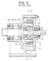
- the illustrated speed changing device is arranged such that a reduced rotation speed is obtained at an output shaft 2 when a torque is input through an input shaft 1.
- This device can be used such that the output shaft 2 is fixed so that a rotation output of a reduced speed is obtained through an internally toothed gear.
- a hollow eccentric shaft 3 is fixed to the input shaft 1 by means of a key (not shown) and a key groove 4.
- the eccentric shaft 3 carries two eccentric members 31 and 32.
- Externally toothed gears 51 and 52 are fitted on the eccentric members 31 and 32 through rollers 6.
- Each of the externally toothed gears 51 and 52 has teeth 7 having trochoidal shape and formed on the outer periphery thereof.
- An internally toothed gear 8, which serves also as an output casing, is fixed in this case.
- the internally toothed gear 8 has arcuate teeth provided by outer pins 9 and meshing with the teeth of the externally toothed gears 51, 52.
- Each outer pin 9 may carry an outer roller.
- the externally toothed gears have inner pin-receiving bores 10 which loosely receive inner pins 11 on which are loosely fitted inner rollers.
- Each of the inner pins is closely fitted in a hole formed in an inner pin holding flange 13.
- the inner roller 12, however, is not essential and may be omitted.
- the inner pin holding flange 13 is formed integrally with the output shaft 2.
- Casings 141 and 142 are united together with the internally toothed gear 8 clamped therebetween.
- a pair of input shaft bearings 151 and 152 which are for supporting the input shaft 1, are provided on both sides of the combination of the externally toothed gears 51 and 52.
- the input shaft bearing 151 is disposed between the outer periphery of the input shaft 1 and the casing 141, while the input shaft bearing 152 is provided between the outer peripheral surface of the input shaft 1 and the surface of a recess 131 formed in the inner pin holding flange 13.
- a pair of output bearings 161, 162 are disposed between the outer peripheral surface of the output shaft 2 and the casing 142.
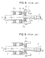
- This known planetary speed reducing device suffers from the following problems.
- the loads W1 and W2 applied to the output shaft 2 act on points which are on the same side of the output shaft bearings 161, 162 as the input shaft 1, so that the output shaft 2 receive these loads in a cantilevered manner. Consequently, a moment is produced to cause the axis of the output shaft 2 to be inclined at an angle ⁇ to the axis O1 of the shaft under no load.
- the load W3 applied to the input shaft 1 acts to produce a moment which, in combination with the inclination of the output shaft 2, causes the input shaft 1 to be inclined at an angle ⁇ to the axis O1.
- the inclinations of the output shaft 2 and the input shaft 1 are attributable to the fact that the input shaft 1 receives the load W3 from the externally toothed gears 51, 52 and that the load W3 is supported by the input bearings 151 and 152.
- Another planetary cycloid transmission assembly is known from GB-A-2 117 081.
- This known transmission discloses the features of the preamble of the claim 1, particularly an double eccentric member coupled on the one hand to an input shaft through an internal tooth or spline type coupling and on the other hand to two externally toothed cycloid discs which in return mesh with rolling members carried by an outer ring member.
- Disposed on both sides of the cycloid discs are discs which support respective ends of pins with a press fit, whereby the pins extend through bores in the cycloid discs.
- the discs carrying the pins are secured to a stationary casing by means of screws.
- a planetary speed changing device comprising: an input shaft; eccentric members coupled to said input shaft through a flexible coupler which permits a relative radial displacement between said input shaft and said eccentric members; a plurality of externally toothed gears fitted on said eccentric members; an internally toothed gear having internal teeth formed by outer pins and meshing with the teeth of said externally toothed gears; inner pin receiving holes formed in said externally toothed gears; inner pins loosely received in said inner pin receiving holes; and inner pin holder rings arranged on both sides of the combination of said externally toothed gears and having holes tightly receiving said inner pins; characterized by flexible coupling means for coupling said inner pin holder rings to an output shaft; and thrust ball bearings provided between each said inner pin holder rings and said eccentric members.
- FIGs. 1 and 2 there is shown a planatary speed changing device embodying the present invention in which rotation of an input shaft 21 is output as a rotation of a reduced speed from an output shaft 22.
- This is not exclusive and the embodiment may be used such that the rotation of a given speed is input to the output shaft 22 and a rotation of an increased speed is taken out from the input shaft 21.
- a hollow eccentric shaft 23 is mounted on the input shaft 21 and is coupled to the input shaft 21 through a flexible coupling means 24 capable of absorbing any radial displacement such as a spline coupler or an Oldham's mechanism.
- a pair of eccentric members 231, 232 are formed on the eccentric shaft 23.
- Externally toothed gears 251, 252 are mounted on the eccentric members 231, 232 through angular bearings 261, 262.
- the angular bearings 261, 262 are composed of ball bearings or roller bearings and have functions to bear both axial and radial loads. These angular bearings 261, 262 are arranged such that they bear forces F1, F2 of opposite directions.
- the externally toothed gears 251, 252 have external teeth 27 having a trochoidal teeth shape.
- An internally toothed gear 28 is formed as a unit with the casing.
- the internally toothed gear 28 has arcuated teeth provided by outer pins 29 which engage with the teeth of the externally toothed gears 251, 252.
- An external roller is loosely mounted on the outer pin 29.
- the externally toothed gears 251, 252 are provided with inner pin receiving bores 30 which loosely receive inner pins 31.
- An inner roller 32 loosely fits on each inner pin 31.
- the inner pins 31 closely fit in bores formed in inner pin holder rings 331, 332 so as to be held by these rings.
- the use of the inner roller 32 is not essential.
- the inner pin holder rings 331, 332 are arranged on both sides of the externally toothed gears 251, 252. Thrust bearings 341, 342 are provided between the inner pin holder rings 331, 332 and the eccentric members 231, 232.
- One 332 of the inner pin holder rings is connected to the output shaft 22 not directly but through a flexible coupling mechanism 35 capable of absorbing offset of axis, e.g., a spline coupler.
- the output shaft of a driving motor M is used as the input shaft 21.
- No bearing is used for supporting the input shaft 21, except the bearing 36 adjacent the motor M.
- a moment is produced to act on the eccentric shaft 23 by the loads exerted by the externally toothed gears 251, 252. According to the invention, this moment is borne by the thrust bearings 341, 342 which are provided on both sides of the eccentric members 231, 232, thus eliminating necessity for radial bearings which would bear this moment.
- This arrangement is one of the remarkable features of the invention. Furthermore, no radial load is transmitted from the eccentric shaft 23 to the input shaft 21 by virtue of the fact that the eccentric shaft 23 and the input shaft 21 are coupled by a radially displaceable joint such as a spline coupler or an Oldham's ring.
- the input shaft 21 receives only a torsional load produced by the torque which is being transmitted, and receives no radial load, with the result that vibration and noise due to oscillation of the input shaft 21 are eliminated.
- bearings for supporting the input shaft 21 are made smaller or may be omitted.
- the above-described face-to-face arrangement of the angular bearings 261, 262 offers also the following advantage.
- the angular bearing 261 acts to displace the angular bearing 262 outwardly, i.e., toward the output shaft 22, whereby the load on the externally toothed gear 252 is increased.
- the above-mentioned face-to-face arrangement of the angular bearings 261, 262 provides an automatic centering function of the externally toothed gears 251, 252, so as to ensure an equal load distribution to both externally toothed gears 251, 252, thus eliminating any abnormal wear, as well as vibration and noise, attributable to uneven load distribution to these gears.
- the present invention offers the following advantages.
- the moment acting on the eccentric shaft can be stably born in lateral directions by the thrust bearings. Furthermore, partly because the eccentric shaft and the input shaft are coupled by a radially displaceable flexible coupling mechanism, and partly because radial load acting on the input shaft is eliminated, it is possible to remarkably suppress vibration and noise attributable to oscillation of the input shaft and to reduce the size of bearings supporting the input shaft or to omit these bearings.
Landscapes
- Engineering & Computer Science (AREA)
- General Engineering & Computer Science (AREA)
- Mechanical Engineering (AREA)
- Retarders (AREA)
Claims (2)
- Planetendrehzahländerungsvorrichtung, umfassend:
eine Eingangswelle (21),
mit der Eingangswelle (21) über ein flexibles Kupplungselement (24), das eine relative Radialverschiebung zwischen der Eingangswelle (21) und den Exzentergliedern (23₁, 23₂) zuläßt, verbundene Exzenterglieder (23₁, 23₂),
eine Anzahl von auf die Exzenterglieder (23₁, 23₂) aufgesetzten außenverzahnten Zahnrädern (25₁, 25₂),
ein innenverzahntes Zahnrad (28) mit Innenzähnen, die durch Außenstifte (29) geformt sind und mit den Zähnen der außenverzahnten Zahnrädern (25₁, 25₂) in Eingriff stehen,
in den außenverzahnten Zahnrädern (25₁, 25₂) geformte Innenstift-Aufnahmebohrungen (30),
in die Innenstift-Aufnahmebohrungen (30) lose eingesetzte Innenstifte (31) und
an beiden Seiten der Kombination aus den außenverzahnten Zahnrädern (25₁, 25₂) angeordnete Innenstift-Halterringe (33₁, 33₂) mit Bohrungen zum Aufnehmen der Innenstifte (31) mit festem Sitz,
gekennzeichnet durch
flexible Kupplungsmittel (35) zum Koppeln oder Verbinden der Innenstift-Halterringe (33₁, 33₂) mit einer Ausgangswelle (22) und
zwischen jedem der Innenstift-Halterringe (33₁, 33₂) sowie der Exzenterglieder (23₁, 23₂) angeordnete Schub- bzw. Axialkugellager (34₁, 34₂). - Planetendrehzahländerungsvorrichtung nach Anspruch 1, wobei die außenverzahnten Zahnräder (25₁, 25₂) auf die Exzenterglieder (23₁, 23₂) über Schräglager (26₁, 26₂) aufgesetzt sind, die so angeordnet sind, daß die Wirklinien dieser Schräglager (26₁, 26₂) zueinander entgegengesetzt sind bzw. einander entgegenwirken.
Priority Applications (3)
| Application Number | Priority Date | Filing Date | Title |
|---|---|---|---|
| EP90117427A EP0474897B1 (de) | 1990-09-10 | 1990-09-10 | Planetenübersetzungsgetriebe |
| DE69019522T DE69019522T2 (de) | 1990-09-10 | 1990-09-10 | Planetenübersetzungsgetriebe. |
| US07/581,623 US5123884A (en) | 1990-09-10 | 1990-09-12 | Planetary speed changing device |
Applications Claiming Priority (1)
| Application Number | Priority Date | Filing Date | Title |
|---|---|---|---|
| EP90117427A EP0474897B1 (de) | 1990-09-10 | 1990-09-10 | Planetenübersetzungsgetriebe |
Publications (2)
| Publication Number | Publication Date |
|---|---|
| EP0474897A1 EP0474897A1 (de) | 1992-03-18 |
| EP0474897B1 true EP0474897B1 (de) | 1995-05-17 |
Family
ID=8204455
Family Applications (1)
| Application Number | Title | Priority Date | Filing Date |
|---|---|---|---|
| EP90117427A Expired - Lifetime EP0474897B1 (de) | 1990-09-10 | 1990-09-10 | Planetenübersetzungsgetriebe |
Country Status (3)
| Country | Link |
|---|---|
| US (1) | US5123884A (de) |
| EP (1) | EP0474897B1 (de) |
| DE (1) | DE69019522T2 (de) |
Families Citing this family (37)
| Publication number | Priority date | Publication date | Assignee | Title |
|---|---|---|---|---|
| US5188572A (en) * | 1990-11-27 | 1993-02-23 | Sumitomo Heavy Industries, Ltd. | Internally meshing planetary gear structure |
| DE69224000T2 (de) * | 1991-08-13 | 1998-04-16 | Sumitomo Heavy Industries | Getriebekonstruktion nach dem Zykloideprinzip |
| FR2684154A1 (fr) * | 1991-11-21 | 1993-05-28 | Staubli Sa Ets | Reducteur de vitesse du type cyclouidal pour robots et autres manipulateurs industriels. |
| JP2866246B2 (ja) * | 1992-02-18 | 1999-03-08 | 住友重機械工業株式会社 | 内接噛合式遊星歯車構造を採用した増減速機シリーズ |
| SK405092A3 (en) * | 1992-12-31 | 1995-09-13 | Jozef Herstek | Multisatelit gear box |
| KR950001733A (ko) * | 1993-06-30 | 1995-01-03 | 배순훈 | 하이퍼 사이클로이드 기어링(Hypo Cycloid Gearing)을 이용한 픽업이송 장치 |
| DE4339218C2 (de) * | 1993-11-18 | 1996-07-18 | Freudenberg Carl Fa | Planetengetriebe für den Antrieb von Nebenaggregaten |
| JPH07332441A (ja) * | 1994-06-01 | 1995-12-22 | Fanuc Ltd | 遊星歯車形減速装置 |
| US5951427A (en) * | 1995-08-14 | 1999-09-14 | Moore Gear And Manufacturing Co. | Planocentric hypocycloidal gear |
| JPH1089425A (ja) * | 1996-09-19 | 1998-04-07 | Hiroyasu Shiokawa | 多段変速機 |
| WO1998022731A1 (en) * | 1996-11-21 | 1998-05-28 | Aimbridge Pty. Ltd. | Double orbital transmission |
| DE19845494C2 (de) † | 1998-10-02 | 2000-07-27 | Krauss Maffei Wegmann Gmbh & C | Kettenfahrzeug |
| DE20023013U1 (de) * | 1999-03-20 | 2002-11-21 | ASEC GmbH, 51702 Bergneustadt | Vorschaltgetriebe an Motoren mit hoher Drehzahl für Hilfsantriebseinheiten |
| TWI223034B (en) * | 2002-08-30 | 2004-11-01 | Sumitomo Heavy Industries | Power transmission device |
| JP4328120B2 (ja) * | 2003-03-31 | 2009-09-09 | 住友重機械工業株式会社 | 揺動内接噛合型遊星歯車装置及びその耐久性向上方法 |
| US20060264294A1 (en) * | 2005-05-18 | 2006-11-23 | Summa David L | Hypocycloidal drive unit for conversion of rotary to linear motion particularly for use in fiberglass insulation production machinery |
| JP2007022197A (ja) * | 2005-07-13 | 2007-02-01 | Kanzaki Kokyukoki Mfg Co Ltd | ホイールモータ装置 |
| EP1743796A3 (de) * | 2005-07-13 | 2007-03-28 | Kanzaki Kokyukoki MFG. Co., Ltd. | Radantrieb mit Raduntersetzungsgetriebe |
| EP2233783B1 (de) | 2005-08-18 | 2012-05-30 | NTN Corporation | Antriebseinheit |
| RU2303724C1 (ru) * | 2006-02-06 | 2007-07-27 | Игорь Аркадьевич Кудрявцев | Планетарно-цевочный редуктор |
| JP2007228689A (ja) * | 2006-02-22 | 2007-09-06 | Denso Corp | 車両用交流発電機の駆動方法 |
| KR101433244B1 (ko) * | 2006-11-03 | 2014-08-22 | 스피네아 에스.알.오. | 기어 |
| JP5060969B2 (ja) * | 2008-01-15 | 2012-10-31 | 住友重機械工業株式会社 | ロボットの関節駆動装置 |
| PL2513510T3 (pl) | 2009-12-18 | 2018-10-31 | Spinea S.R.O. | Przekładnia |
| CN102954190B (zh) * | 2011-08-19 | 2015-09-09 | 鸿富锦精密工业(深圳)有限公司 | 减速装置 |
| TW201430240A (zh) * | 2013-01-21 | 2014-08-01 | Harmonic Innovation Technology Co Ltd | 諧波減速裝置 |
| CN103267101A (zh) * | 2013-04-28 | 2013-08-28 | 浙江澳太机械制造有限公司 | 一种少齿差行星减速机 |
| JP2017145851A (ja) * | 2016-02-16 | 2017-08-24 | 株式会社 神崎高級工機製作所 | 油圧装置及び減速機構付き駆動ユニット |
| FR3050504B1 (fr) | 2016-04-25 | 2020-02-14 | Jtekt Europe | Reducteur cycloidal avec rattrapage automatique de jeu et systeme de direction assistee pourvu d’un tel reducteur |
| JP6859039B2 (ja) * | 2016-07-12 | 2021-04-14 | ナブテスコ株式会社 | 歯車装置 |
| US10563729B2 (en) * | 2018-01-08 | 2020-02-18 | Schaeffler Technologies AG & Co. KG | Hyper-cycloidal differential |
| CN110131008A (zh) * | 2018-02-02 | 2019-08-16 | 博格华纳公司 | 双致动可变凸轮 |
| US10378613B1 (en) * | 2018-02-07 | 2019-08-13 | Schaeffler Technologies AG & Co. KG | Electric powertrain with cycloidal mechanism |
| JP7048049B2 (ja) * | 2018-03-16 | 2022-04-05 | 日本トムソン株式会社 | サイクロイド減速機 |
| IT201900004871A1 (it) * | 2019-04-01 | 2020-10-01 | Omme Gears S A S | Riduttore cicloidale |
| KR20220044483A (ko) * | 2019-06-13 | 2022-04-08 | 서큘러 웨이브 드라이브 파트너스 인크. | 원형 파동 드라이브 |
| TWI751833B (zh) * | 2020-12-11 | 2022-01-01 | 上銀科技股份有限公司 | 具有預壓調整裝置之擺線式減速機 |
Family Cites Families (15)
| Publication number | Priority date | Publication date | Assignee | Title |
|---|---|---|---|---|
| US2970694A (en) * | 1958-04-18 | 1961-02-07 | Nordberg Manufacturing Co | Drive and coupling for screens |
| GB955097A (en) * | 1960-05-16 | 1964-04-15 | Braren Rudolf | Planetary gear |
| US3160032A (en) * | 1961-05-25 | 1964-12-08 | Black Tool Inc | Epicyclic speed changing device and gear form therefor |
| US3424036A (en) * | 1967-01-17 | 1969-01-28 | Rex Chainbelt Inc | Speed changing device |
| US3726158A (en) * | 1971-02-04 | 1973-04-10 | H Brown | Speed-reducing coupling |
| US4183267A (en) * | 1978-07-10 | 1980-01-15 | Caterpillar Tractor Co. | Nested bearing crank mechanism |
| US4567790A (en) * | 1981-11-18 | 1986-02-04 | Emerson Electric Company | Motion transmitting system |
| US4549450A (en) * | 1982-02-25 | 1985-10-29 | Pierrat Michel A | Orbital speed reducer with compensation coupling |
| DE3206992A1 (de) * | 1982-02-26 | 1983-09-08 | Rudolf Braren | Zykloidengetriebe |
| US4478100A (en) * | 1982-03-08 | 1984-10-23 | Sfredda Albert P | Automatic transmission |
| JPS60129454A (ja) * | 1983-12-19 | 1985-07-10 | Sumitomo Heavy Ind Ltd | 遊星歯車増・減速機 |
| US4552037A (en) * | 1984-02-10 | 1985-11-12 | Advanced Energy Concepts '81 Ltd. | Retainer for epicyclic transmission |
| JPS612947A (ja) * | 1984-06-15 | 1986-01-08 | Sumitomo Heavy Ind Ltd | 遊星歯車増減速機 |
| JPS61252934A (ja) * | 1985-04-30 | 1986-11-10 | Nippon Air Brake Co Ltd | クロ−ラ車両の走行装置用減速機 |
| JPH0627532B2 (ja) * | 1987-04-13 | 1994-04-13 | 住友重機械工業株式会社 | 遊星歯車増減速機 |
-
1990
- 1990-09-10 DE DE69019522T patent/DE69019522T2/de not_active Expired - Fee Related
- 1990-09-10 EP EP90117427A patent/EP0474897B1/de not_active Expired - Lifetime
- 1990-09-12 US US07/581,623 patent/US5123884A/en not_active Expired - Lifetime
Also Published As
| Publication number | Publication date |
|---|---|
| DE69019522T2 (de) | 1995-10-19 |
| US5123884A (en) | 1992-06-23 |
| EP0474897A1 (de) | 1992-03-18 |
| DE69019522D1 (de) | 1995-06-22 |
Similar Documents
| Publication | Publication Date | Title |
|---|---|---|
| EP0474897B1 (de) | Planetenübersetzungsgetriebe | |
| US4621543A (en) | Planetary torque converter | |
| KR920000037B1 (ko) | 감속 전동 기구 | |
| CA1209823A (en) | Epicyclic transmission having free rolling roller driving elements | |
| US20020111243A1 (en) | Driving apparatus | |
| US3427901A (en) | Gearing | |
| WO2001081789A1 (en) | Transmission internally meshing a planetary gear structure | |
| US3839922A (en) | Transmission gear | |
| US4491033A (en) | Double eccentric wave generator arrangement | |
| EP0287037B1 (de) | Planetenradgetriebevorrichtung | |
| CA2379240C (en) | Gearing for power sharing in planetary transmission | |
| US4770062A (en) | Planetary gear apparatus | |
| US6179743B1 (en) | Gearing for power sharing in planetary transmission | |
| EP4141287B1 (de) | Getriebemechanismus | |
| JP3920398B2 (ja) | 内接噛合遊星歯車構造 | |
| JPH0570013B2 (de) | ||
| US6338691B1 (en) | Gearing for power sharing in planetary transmission | |
| JP2743285B2 (ja) | 遊星歯車増減速装置 | |
| CA2024628C (en) | Planetary speed changing device | |
| JP2523068Y2 (ja) | 内接噛合遊星歯車構造 | |
| US5255895A (en) | Gear transmission in a lifting machinery | |
| JPS62101943A (ja) | 減速装置 | |
| JPH0627867Y2 (ja) | 遊星歯車増減速機における出力軸の連結装置 | |
| JP2509108Y2 (ja) | 内接噛合遊星歯車構造 | |
| JP2523069Y2 (ja) | 内接噛合遊星歯車構造 |
Legal Events
| Date | Code | Title | Description |
|---|---|---|---|
| PUAI | Public reference made under article 153(3) epc to a published international application that has entered the european phase |
Free format text: ORIGINAL CODE: 0009012 |
|
| AK | Designated contracting states |
Kind code of ref document: A1 Designated state(s): CH DE FR GB IT LI SE |
|
| 17P | Request for examination filed |
Effective date: 19920721 |
|
| 17Q | First examination report despatched |
Effective date: 19940303 |
|
| GRAA | (expected) grant |
Free format text: ORIGINAL CODE: 0009210 |
|
| RBV | Designated contracting states (corrected) |
Designated state(s): DE |
|
| AK | Designated contracting states |
Kind code of ref document: B1 Designated state(s): DE |
|
| REF | Corresponds to: |
Ref document number: 69019522 Country of ref document: DE Date of ref document: 19950622 |
|
| PLBE | No opposition filed within time limit |
Free format text: ORIGINAL CODE: 0009261 |
|
| STAA | Information on the status of an ep patent application or granted ep patent |
Free format text: STATUS: NO OPPOSITION FILED WITHIN TIME LIMIT |
|
| 26N | No opposition filed | ||
| PGFP | Annual fee paid to national office [announced via postgrant information from national office to epo] |
Ref country code: DE Payment date: 20010924 Year of fee payment: 12 |
|
| PG25 | Lapsed in a contracting state [announced via postgrant information from national office to epo] |
Ref country code: DE Free format text: LAPSE BECAUSE OF NON-PAYMENT OF DUE FEES Effective date: 20030401 |