EP0282333B1 - Motorrad - Google Patents
Motorrad Download PDFInfo
- Publication number
- EP0282333B1 EP0282333B1 EP88302155A EP88302155A EP0282333B1 EP 0282333 B1 EP0282333 B1 EP 0282333B1 EP 88302155 A EP88302155 A EP 88302155A EP 88302155 A EP88302155 A EP 88302155A EP 0282333 B1 EP0282333 B1 EP 0282333B1
- Authority
- EP
- European Patent Office
- Prior art keywords
- frame
- motorcycle
- seat
- front frame
- shaft
- Prior art date
- Legal status (The legal status is an assumption and is not a legal conclusion. Google has not performed a legal analysis and makes no representation as to the accuracy of the status listed.)
- Expired - Lifetime
Links
- 230000005540 biological transmission Effects 0.000 description 3
- 238000013459 approach Methods 0.000 description 1
- 230000008878 coupling Effects 0.000 description 1
- 238000010168 coupling process Methods 0.000 description 1
- 238000005859 coupling reaction Methods 0.000 description 1
- 230000001419 dependent effect Effects 0.000 description 1
- 238000007599 discharging Methods 0.000 description 1
- 230000000694 effects Effects 0.000 description 1
- 239000002828 fuel tank Substances 0.000 description 1
- 230000005484 gravity Effects 0.000 description 1
Images


Classifications
-
- F—MECHANICAL ENGINEERING; LIGHTING; HEATING; WEAPONS; BLASTING
- F02—COMBUSTION ENGINES; HOT-GAS OR COMBUSTION-PRODUCT ENGINE PLANTS
- F02B—INTERNAL-COMBUSTION PISTON ENGINES; COMBUSTION ENGINES IN GENERAL
- F02B61/00—Adaptations of engines for driving vehicles or for driving propellers; Combinations of engines with gearing
- F02B61/02—Adaptations of engines for driving vehicles or for driving propellers; Combinations of engines with gearing for driving cycles
-
- B—PERFORMING OPERATIONS; TRANSPORTING
- B62—LAND VEHICLES FOR TRAVELLING OTHERWISE THAN ON RAILS
- B62K—CYCLES; CYCLE FRAMES; CYCLE STEERING DEVICES; RIDER-OPERATED TERMINAL CONTROLS SPECIALLY ADAPTED FOR CYCLES; CYCLE AXLE SUSPENSIONS; CYCLE SIDE-CARS, FORECARS, OR THE LIKE
- B62K11/00—Motorcycles, engine-assisted cycles or motor scooters with one or two wheels
-
- B—PERFORMING OPERATIONS; TRANSPORTING
- B62—LAND VEHICLES FOR TRAVELLING OTHERWISE THAN ON RAILS
- B62K—CYCLES; CYCLE FRAMES; CYCLE STEERING DEVICES; RIDER-OPERATED TERMINAL CONTROLS SPECIALLY ADAPTED FOR CYCLES; CYCLE AXLE SUSPENSIONS; CYCLE SIDE-CARS, FORECARS, OR THE LIKE
- B62K25/00—Axle suspensions
- B62K25/005—Axle suspensions characterised by the axle being supported at one end only
Definitions
- the present invention relates to a motorcycle.
- centrifugal forces produced dependent on the weight of the motorcycle, the speed of travel of the motorcycle, and the cornering radius are counterbalanced by centripetal forces generated by causing the motorcycle to bank.
- Conventional motorcycles have unitary frames supporting front and rear wheels. Upon cornering at high speed, the motorcycle frame is required to bank to a large degree.
- the front and rear wheels supported on conventional motorcycle frames have tires of circular cross section which are shaped to allow the motorcycle frames to bank.
- GB 2082987 discloses a three-wheel vehicle comprising an engine bearing sub frame which is maintained substantially upright by a pair of rear road wheels disposed at either side of the subframe.
- the vehicle further comprises a main frame to which are connected the vehicle rider's seat, the steering assembly and the single steerable front wheel.
- the main frame is connected to the subframe by a coupling which enables the main frame to bank relative to the subframe.
- a motorcycle comprising: a front and a rear wheel; a frame assembly including a front frame supporting the front wheel, a main frame supporting the rear wheel, and connecting means interconnecting the front and main frames, the said means being disposed in a longitudinal direction of the frame assembly, the front frame being capable of banking laterally about the connecting means, characterized in that the single rear wheel is capable of preventing the main frame from banking laterally, and in that the frame assembly further comprises a seat frame, swingably mounted on the front frame.
- the connecting means includes a connecting shaft disposed in the longitudinal direction of the frame assembly.
- the rear wheel includes a tyre having a broad U-shaped cross section; the tyre preferably having a flat central ground engaging portion.
- the steering handle is preferably mounted on the front frame for steering the front wheel.
- the seat frame extends above the main frame.
- the driver's seat and foot rests may be mounted on the seat frame.
- the driver's seat may be mounted on the seat frame and the driver's foot rests may be mounted on the main frame.
- a mechanism may be provided for limiting the range in which the front frame banks.
- a device is provided for angularly moving the seat frame according to a banking angle of the front frame.
- the device may include means for angularly moving the seat frame in a direction in which the front frame banks.
- the banking angle of the front frame is reduced and the burden on the front wheel is smaller by an extent commensurate with the centripetal forces produced by angularly moving the seat frame.
- the seat frame can be angularly moved in the same direction as the banking direction of the front frame, the degree to which the front frame banks is reduced for high-speed cornering.
- FIGS. 1 to 6 A motorcycle according a first embodiment of the present invention will be described below with reference to FIGS. 1 to 6.
- the motorcycle has a front cowl 40, a pair of lateral extensions 41 projecting laterally from the front cowl 40, a pair of radiators 42 disposed in front openings 43 of the extensions 41, the extensions 41 having rear openings 44 for discharging air which has been introduced from the front openings 43 and passed through the radiators 42, a rear drive wheel 44 including a wide flat tire of a substantially U-shaped cross section, a front wheel 45 including a round tire, and a driver's riding seat 46.
- the inner structure includes a front frame 47, a main frame 48, and a seat frame 49.
- the front wheel 45 is supported on a steering shaft 51 by an axle 50.
- the steering shaft 51 has upper and lower ends coupled by pillow balls 52, 53 to ends of upper and lower swing arms 54, 55, respectively, the other ends of which are connected to the front frame 47.
- the swing arms 54, 55 are vertically swingable about their joints to the front frame 47 and also about the pillow balls 52, 53.
- a steering rod 57 has one end attached to the steering shaft 51 below the upper pillow ball 52.
- the other end of the steering rod 57 is attached to a lower portion of a handle 56 mounted on a front end of the front frame 47.
- the handle 56 is angularly movable in a plane normal to a plane formed by the steering shaft 51 and the upper and lower swing arms 54, 55 and substantially parallel to the upper swing arm 54.
- a damper unit 58 is coupled to the lower swing arm 55 and the front frame 47 for correcting vertical movement of a front portion of the motorcycle.
- the damper unit 58 has one end coupled to the lower swing arm 55 by a link 59 and a bracket 60, and also to a bracket 62 mounted on the front frame 47 through the link 59 and a link 61.
- An engine 63 and a transmission case 64 are mountred on the main frame 48.
- the main frame 48 has a basde portion 65 joined coaxially to a connecting shaft 66 of the front frame 47. Footsteps 67 are mounted on a lower portion of the main frame 48.
- the seat frame 49 disposed upwardly of the front frame 47 is pivotally supported on an attachment shaft 68 attached to the front frame 47 along a straight line connecting the joints between the upper and lower swing arms 54, 55 and the front frame 47.
- the seat frame 49 is angularly movable about the attachment shaft 68, and can bank, together with the front frame 47, about the connecting shaft 66 by which the front frame 47 and the base portion 65 of the main frame 48 are coupled to each other.
- the driver's riding seat 46 with a fuel tank 69 disposed therein is disposed on the seat frame 49 above the main frame 48.
- a mechanism for angularly moving the seat frame 49 and the front frame 47 includes a connecting bracket 70 joined to the seat frame 49, a connecting member 71 pivoted to the connecting bracket 70, and a connecting member 72 pivoted to the connecting member 71 and swingable with the connecting shaft 66.
- the seat frame 49 is thus coupled to the main frame 48 through the connecting bracket 70 and the connecting members 71, 72.
- the seat frame 49 is also coupled to the front frame 47 through the connecting member 72, a connecting member 73 pivoted to the connecting member 72, and a connecting bracket 74 pivoted to the connecting member 73 and joined to the front frame 47.
- the bracket 70 and the connecting members 71, 72, 73 are connected by shafts 75a, 75b, 76a, 76b parallel to the connecting shaft 66, and angularly movable about these shafts 75a, 75b, 76a, 76b.
- the transmission case 64 has a sprocket 78, and a sprocket 79 is attached to the axle of the rear wheel 44, with an endless chain 80a being trained around the sprockets 78, 79.
- Upper and lower swing arms 81, 82 have ends pivoted to the transmission case 64 and extend between hte sprocket 79 and the axle of the rear wheel 44.
- the other ends of the upper and lower swing arms 81, 82 are coupled to upper and lower ends of a knuckle arm 80b mounted coaxially with and slidably against the axle of the rear wheel 44.
- a rear cushion 85 is mounted on the main frame 48 and coupled to a lower surface of the lower swing arm 82 through a bracket 83 and a link 84.
- the front wheel 45 and the front frame 47 are caused to bank upon cornering.
- the rear wheel 44 is however prevented from banking because it includes a wide flat tire and also because the front frame 47 is swingable about the connecting shaft 66.
- the wide flat rear wheel 44 does not bank, it provides a large area of contact with ground upon cornering.
- the front frame 47 banks, the seat frame 49 banks and swings about the attachment shaft 68. Therefore, the center of gravity of the motorcycle can be shifted laterally a large distance. As a result, the motorcycle can make a high-speed turn.
- the steps 67 may be mounted on the seat frame 49 if the angle of swinging movement of the seat frame 49 is to be increased.
- FIGS. 7 and 8 show a motorcycle according to a second embodiment of the present invention, the motorcycle being partly different from the motorcycle shown in FIG. 6.
- the seat frame 49 is coupled to the front frame 47 through a connecting bracket 70 of the frame 49, connecting members 86, 89, 90, and a connecting bracket 91.
- the connecting member 89 has its inrermediate portion pivotally connected to a connecting shaft 89a, parallel to the connecting shaft 66, of a connecting bracket 87 of the base portion 65, so that the connecting member 89 is coupled to the main frame 48.
- the brackets 70, 91 and the connecting members 86, 90, 89 are angularly movably coupled to connecting shafts 92, 93, 94, 95 parallel to the connecting shaft 66.
- the bracket 91 is turned to enable the seat frame 49 to turn around the connecting shaft 66 in the direction of the arrow Y2 through the connecting members 90, 89, 86, 70.
- FIGS. 9 and 10 show a motorcycle according to a third embodiment, the views illustrating a device or mechanism for angularly moving the seat frame.
- the seat frame 49 is connected to the main frame 48 through the bracket 70 of the frame 49, a connecting member 96, and connecting members 100, 97 to a connecting bracket 98 of the base portion 65, so that the seat frame 49 is coupled to the main frame 48.
- the seat frame 49 is also connected to the front frame 47 through the connecting member 100 pivotally coupled to the connecting bracket 91 by a connecting shaft 99 parallel to the connecting shaft 66.
- the brackets 70, 98 and the connecting members 96, 100, 97 are angularly movably coupled to connecting shafts 101, 102, 103, 104 parallel to the connecting shaft 66.
- FIGS. 11 and 12 show a motorcycle according to a fourth embodiment, the views illustrating a device or mechanism for angularly moving the seat frame.
- the seat frame 49 is coupled to the main frame 48 by the bracket 70 of the frame 49, a connecting member 106 having one end connected to the bracket 70 by a pivot shaft 105 parallel to the connecting shaft 66, and a movable gear 109 having one end connected to the other end of the connecting member 106 by a pivot shaft 107 parallel to the shaft 66 and the other end meshing with a fixed gear 108 on the base portion 65 of the main frame 48.
- the gear 109 is coupled to the front frame 47 by a connecting bracket 91 connected to an intermediate portion of the gear 109 by a pivot shaft 110 parallel to the shaft 66.
- FIGS. 13 and 14 show a device or mechanism for angularly moving the seat frame of a motorcycle according to a fifth embodiment of the present invention.
- the seat frame 49 is coupled to the main frame 48 by the attachment shaft 68, a connecting member 111 having one end connected to the shaft 68, and an L-shaped connecting member 116 having one end coupled to the other end of the member 111 by a pivot shaft 112 and the other end connected to one end of an L-shaped connecting member 114 by a pivot shaft 115, the L-shaped connecting member 114 being swingable about an attachment shaft 113 on the base portion 65.
- the seat frame 49 is also coupled to the front frame 47 by a connecting member 118 joined to the other end of the connecting member 114 by a pivot shaft 117.
- the seat frame 49 is turned about the attachment shaft 68 in the direction of the arrow Y2 through the connecting members 118, 114, 116, 111.
- the connecting member 114 may be coupled to the front frame 47, whereas the base portion 65 of the connecting member 118 may be coupled to the main frame 48.
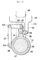
- FIGS. 15 and 16 show a device or mechanism for angularly moving the seat frame of a motorcycle according to a sixth embodiment of the present invention.
- the seat frame 49 is coupled to the main frame 48 by the attachment shaft 68, a connecting member 119 with one end joined to the shaft 68, a connecting member 121 having one end coupled to the other end of the connecting member 119 by a pivot shaft 120, and a swing gear 124 swingably coupled to the other end of the member 121 by a pivot shaft 122, the swing gear 124 being swingable about an attachment shaft 123 on the base portion 65 of the main frame 48.
- the seat frame 49 is also connected to the front frame 47 through a fixed gear 125 secured to the front frame 47 and held in mesh with the swing gear 124.
- the seat frame 49 is turned about the shaft 68 in the direction of the arrow Y2 through the gears 125, 124 and the connecting members 121, 119.
- the swing gear 124 may be mounted on the front frame 47, and the fixed gear 125 may be mounted on the base portion 65 of the main frame 48.
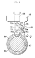
- FIGS. 17 and 18 show a device or mechanism for angularly moving the seat frame of a motorcycle according to a seventh embodiment of the present invention.
- the seat frame 49 is coupled to the main frame 48 by the attachment shaft 68, a bevel gear 126 mounted on the lower end of the shaft 68, and a bevel gear 128 meshing with the bevel gear 126 and mounted on an end of a connecting shaft 127 extending from the base portion 65 of the main frame 48 coaxially with the connecting shaft 66 through the front frame 47.
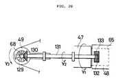
- FIGS.19 and 20 show a device or mechanism for angularly moving the seat frame of a motorcycle according to an eighth embodiment of the present invention.
- the seat frame 49 is coupled to the main frame 48 by the attachment shaft 68, a bevel gear 129 mounted on the lower end of the shaft 68, a bevel gear 130 meshing with the bevel gear 129 and mounted on one end of a connecting shaft 131, and a rotatable gear 132 mounted on the other end of the connecting shaft 131 and meshing with a fixed gear 133 fixed to the base portion 65 of the main frame 48.
- the rotatable gear 132 rotates in the direction of the arrow Y2 in mesh with the fixed gear 133, and the gear 129 is rotated in the direction of the arrow Y3 by the gear 130, so that the seat frame 49 is turned with the shaft 68 in the direction of the arrow Y3.
- FIG. 21 shows a motorcycle according to a ninth embodiment, the motorcycle having a device or mechanism for angularly moving the seat frame.
- the seat frame 49 is coupled to the main frame 48 by the attachment shaft 68, a hyraulic motor 134 mounted on the shaft 68, a hydraulic circuit 135 having one end connected to the hydraulic motor 134 , and a hydraulic pressure generating mechanism 136 connected to the other end of the hydraulic circuit 135 and having one end coupled to the base portion 65 of the main frame 48 coaxially with the connecting shaft 66, the hydraulic pressure generating mechanism 136 being disposed in the front frame 47.
- the hydraulic pressure generating mechanism 136 generates a hydraulic pressure corresponding to the banking angle of the front frame 47 with respect to the base portion 65 of the main frame 48.
- a hydraulic pressure generated by the hydraulic pressure generating mechanism 136 is applied via the circuit 135 to the hydraulic motor 134.
- the shaft 68 and the seat frame 49 are turned in the direction of the arrow Y2 by a control mechanism (not shown) which controls the direction of rotation of the motor 134 according to the direction in which the front frame 47 banks.
Claims (10)
- Ein Motorrad mit: einem Vorder- und einem Hinterrad (45,44); einer Rahmenanordnung, die einen das Vorderrad (45) abstützenden Vorderrahmen (47), einen das Hinterrad (44) abstützenden Hauptrahmen (48) und eine Verbindungseinrichtung umfaßt, die den Vorder- und den Hauptrahmen (47,48) miteinander verbindet, wobei diese Einrichtung in Längsrichtung der Rahmenanordnung angeordnet und der Vorderrahmen (47) seitlich um die Verbindungseinrichtung kippbar ist, dadurch gekennzeichnet, daß das einzige Hinterrad (44) geeignet ist, den Hauptrahmen (48) am seitlichen Kippen zu hindern, und daß die Rahmenanordnung ferner einen Sitzrahmen (49) umfaßt, der schwingbar am Vorderrahmen (47) montiert ist.
- Ein Motorrad nach Anspruch 1, dadurch gekennzeichnet, daß die Verbindungseinrichtung einen Verbindungsschaft (66) umfaßt, der in Längsrichtung der Rahmenanordnung angeordnet ist.
- Ein Motorrad nach Anspruch 1 oder 2, dadurch gekennzeichnet, daß das Hinterrad (44) einen Reifen mit einem breiten U-förmigen Querschnitt umfaßt.
- Ein Motorrad nach einem der Ansprüche 1 bis 3, dadurch gekennzeichnet, daß das Hinterrad (44) einen Reifen mit einem ebenen zentralen Bodeneingriffsabschnitt umfaßt.
- Ein Motorrad nach einem der vorhergehenden Ansprüche, dadurch gekennzeichnet, daß eine Lenkstange (56) zum Lenken des Vorderrades (45) am Vorderrahmen (47) befestigt ist; und daß der Sitzrahmen (49) sich oberhalb des Hauptrahmens (47) erstreckt.
- Ein Motorrad nach Anspruch 5, dadurch gekennzeichnet, daß ein Fahrersitz (46) und Fußstützen (67) am Sitzrahmen (49) befestigt sind.
- Ein Motorrad nach Anspruch 5, dadurch gekennzeichnet, daß ein Fahrersitz (46) am Sitzrahmen (49) befestigt ist und die Fußstützen (67) für den Fahrer am Hauptrahmen (48) befestigt sind.
- Ein Motorrad nach einem der vorhergehenden Ansprüche, dadurch gekennzeichnet, daß eine Einrichtung zum Begrenzen des Bereichs, innerhalb welchem der Vorderrahmen (47) seitlich kippt, vorgesehen ist.
- Ein Motorrad nach einem der vorhergehenden Ansprüche, dadurch gekennzeichnet, daß eine Vorrichtung (134,135,136) zur Drehbewegung des Sitzrahmens (49) in Übereinstimmung mit einem Kippwinkel des Vorderrahmens (47) vorgesehen ist.
- Ein Motorrad nach Anspruch 9, dadurch gekennzeichnet, daß die Vorrichtung (134,135,136) eine Einrichtung zur Drehbewegung des Sitzrahmens (49) in einer Richtung, in der der Vorderrahmen (47) kippt, umfaßt.
Applications Claiming Priority (6)
| Application Number | Priority Date | Filing Date | Title |
|---|---|---|---|
| JP5923687A JPS63222991A (ja) | 1987-03-13 | 1987-03-13 | 自動2輪車 |
| JP59236/87 | 1987-03-13 | ||
| JP203511/87 | 1987-08-18 | ||
| JP20351187A JPS6447691A (en) | 1987-08-18 | 1987-08-18 | Motorcycle |
| JP204163/87 | 1987-08-19 | ||
| JP62204163A JPS6447690A (en) | 1987-08-19 | 1987-08-19 | Motorcycle |
Publications (3)
| Publication Number | Publication Date |
|---|---|
| EP0282333A2 EP0282333A2 (de) | 1988-09-14 |
| EP0282333A3 EP0282333A3 (en) | 1989-11-29 |
| EP0282333B1 true EP0282333B1 (de) | 1993-10-13 |
Family
ID=27296817
Family Applications (1)
| Application Number | Title | Priority Date | Filing Date |
|---|---|---|---|
| EP88302155A Expired - Lifetime EP0282333B1 (de) | 1987-03-13 | 1988-03-11 | Motorrad |
Country Status (4)
| Country | Link |
|---|---|
| US (4) | US4917209A (de) |
| EP (1) | EP0282333B1 (de) |
| BR (1) | BR8801115A (de) |
| DE (1) | DE3884830T2 (de) |
Families Citing this family (34)
| Publication number | Priority date | Publication date | Assignee | Title |
|---|---|---|---|---|
| JPH068114B2 (ja) * | 1987-03-13 | 1994-02-02 | 本田技研工業株式会社 | 自動2輪車 |
| DE3909258A1 (de) * | 1988-03-23 | 1989-10-05 | Honda Motor Co Ltd | Motorrad |
| JPH0268283A (ja) * | 1988-09-05 | 1990-03-07 | Honda Motor Co Ltd | 前輪駆動車の自動二輪車 |
| US5248019A (en) * | 1988-11-02 | 1993-09-28 | Sm Sbarro Mottas Engineering S.A. | Hub-less cycle or engine-driven vehicle |
| FR2642391B1 (fr) * | 1989-01-30 | 1991-05-03 | Sbarro Mottas Eng | Vehicule motorise ou tracte muni d'une roue directrice a deux roulements |
| US5054572A (en) * | 1990-06-20 | 1991-10-08 | Parker James G | Front wheel drive system for a motorcycle |
| AU644903B2 (en) * | 1990-10-01 | 1993-12-23 | Ronald Brian Carrington | Patient restrainer |
| US5485893A (en) * | 1993-06-29 | 1996-01-23 | Summers; Thomas W. | Vehicle |
| US5613571A (en) * | 1995-09-26 | 1997-03-25 | Harley-Davidson, Inc. | Rotational speed/tip sensor |
| BE1010650A3 (nl) * | 1996-09-26 | 1998-11-03 | Vanmeerbeek Jan | Voertuig. |
| NL1005894C2 (nl) * | 1997-04-24 | 1998-10-27 | Brinks Westmaas Bv | Kantelbaar voertuig. |
| WO1999050133A1 (en) | 1998-03-31 | 1999-10-07 | Nemeth Janos | Motorcycle construction |
| US6012539A (en) * | 1998-05-01 | 2000-01-11 | Patmont Motor Werks | All terrain scooter |
| US6213237B1 (en) * | 1998-10-23 | 2001-04-10 | David Willman | Motorcycle stop support wheels |
| US6668959B2 (en) | 2002-05-16 | 2003-12-30 | Patmont Motor Werks | Scooter with integral frame mounted shock absorber |
| NL1021195C2 (nl) * | 2002-07-31 | 2004-02-03 | Brinks Westmaas Bv | Kantelvoertuig. |
| US7006901B2 (en) * | 2002-11-18 | 2006-02-28 | Wang Everett X | Computerized automated dynamic control system for single-track vehicles |
| US7097187B2 (en) * | 2002-12-20 | 2006-08-29 | Daimlerchrysler Corporation | Suspension system for a motor vehicle |
| JP4482442B2 (ja) * | 2004-12-27 | 2010-06-16 | ヤマハ発動機株式会社 | 車両 |
| JP4614837B2 (ja) | 2005-07-12 | 2011-01-19 | ヤマハ発動機株式会社 | 車両 |
| JP2007125917A (ja) * | 2005-11-01 | 2007-05-24 | Yamaha Motor Co Ltd | 制御システムおよびそれを備えた自動二輪車 |
| TWM295086U (en) * | 2006-03-07 | 2006-08-01 | Yi-Shin He | Power-driven vehicle steering controlled by twisting or swaying body |
| ES2326764B1 (es) * | 2006-11-02 | 2010-07-15 | Santiago Fernandez Dotor | Dispositivo de posicionamiento variable para asientos de motocicleta. |
| US7967096B2 (en) * | 2008-03-20 | 2011-06-28 | Zuumcraft, Inc. | Lean steering truck with a torsion spring assembly |
| WO2010053520A1 (en) | 2008-11-04 | 2010-05-14 | Performance Concepts, Inc. | Self-propelled vehicle and articulated steerable mobile chassis thereof |
| US8128111B2 (en) * | 2009-09-04 | 2012-03-06 | Zike, Llc | Scooter and pedal drive assembly |
| US9114848B2 (en) * | 2009-09-04 | 2015-08-25 | Zike, Llc | Pedal-drive system for manually propelling multi-wheeled cycles |
| US8640809B2 (en) * | 2010-01-05 | 2014-02-04 | Honda Motor Company, Ltd. | Flywheel assemblies and vehicles including same |
| US8653681B2 (en) | 2011-04-04 | 2014-02-18 | Honda Motor Co., Ltd. | Power equipment apparatus having flywheel assembly |
| KR101333716B1 (ko) * | 2011-12-26 | 2013-11-28 | 현대자동차주식회사 | 삼륜차량의 후륜서스펜션 |
| EP2628972B1 (de) * | 2012-02-20 | 2016-07-20 | Rosta AG | Gummifederelement-Drehwinkelmess-system und dessen Verwendung |
| US9168970B2 (en) | 2013-03-15 | 2015-10-27 | Honda Motor Co., Ltd. | Flywheel assemblies and vehicles including same |
| US9428236B2 (en) * | 2013-11-06 | 2016-08-30 | Bryan Goss | Lean-compensating motorcycle with channel wheels |
| US10053180B1 (en) * | 2017-08-31 | 2018-08-21 | Tower Trikes, Inc. | Trike steering and suspension systems |
Family Cites Families (19)
| Publication number | Priority date | Publication date | Assignee | Title |
|---|---|---|---|---|
| GB239365A (en) * | 1924-09-17 | 1925-09-10 | Brooks J B & Co Ltd | Improvements relating to foot-rests for use with pillion seats for motor-cycles |
| US3504934A (en) * | 1966-06-30 | 1970-04-07 | George L Wallis | Tricycle wheel and frame arrangement |
| US3531138A (en) * | 1968-08-27 | 1970-09-29 | Walter H Sorensen | Bicycle safety device |
| US3893533A (en) * | 1974-01-25 | 1975-07-08 | Hubert Tidwell | Recreational vehicle |
| US3938609A (en) * | 1974-01-28 | 1976-02-17 | Daihatsu Motor Company Limited | Tricycle |
| US3912031A (en) * | 1974-06-14 | 1975-10-14 | Leo Goulet | Convertible vehicle for all seasons |
| JPS55144190U (de) * | 1979-04-05 | 1980-10-16 | ||
| CA1158175A (en) * | 1980-08-29 | 1983-12-06 | Frank J. Winchell | Three-track motorcycle with cambering main frame |
| US4437535A (en) * | 1980-08-29 | 1984-03-20 | General Motors Corporation | Three-track motorcycle with cambering main frame |
| JPS5812873A (ja) * | 1981-07-14 | 1983-01-25 | 本田技研工業株式会社 | 揺動式三輪車のローリングロック装置 |
| JPS5820581A (ja) * | 1981-07-24 | 1983-02-07 | 本田技研工業株式会社 | 車両のフレ−ム構造 |
| US4423795A (en) * | 1982-02-19 | 1984-01-03 | General Motors Corporation | Wheeled vehicle with cambering front module |
| GB2116497B (en) * | 1982-03-17 | 1986-01-22 | Honda Motor Co Ltd | Motor tricycles |
| US4506754A (en) * | 1982-08-18 | 1985-03-26 | Yamaha Hatsudoki Kabushiki Kaisha | Motorcycle frame with adjustable and compact rider support |
| US4466631A (en) * | 1982-09-27 | 1984-08-21 | Allis-Chalmers Corporation | Ball joint assembly for draft arm |
| US4546993A (en) * | 1983-10-13 | 1985-10-15 | Walker George R | Adjustable motorcycle passenger floorboard |
| JPS6124383U (ja) * | 1984-07-19 | 1986-02-13 | 本田技研工業株式会社 | 自動二輪車の路肩灯装置 |
| JPS61139575A (ja) * | 1984-12-07 | 1986-06-26 | 本田技研工業株式会社 | 揺動型車両の揺動規制装置 |
| FR2583704A1 (fr) * | 1985-06-21 | 1986-12-26 | Eb Bernard | Motocycle de competition comportant un cadre basculant par rapport au plan des roues |
-
1988
- 1988-03-11 BR BR8801115A patent/BR8801115A/pt unknown
- 1988-03-11 DE DE88302155T patent/DE3884830T2/de not_active Expired - Fee Related
- 1988-03-11 EP EP88302155A patent/EP0282333B1/de not_active Expired - Lifetime
- 1988-07-15 US US07/219,508 patent/US4917209A/en not_active Expired - Fee Related
-
1989
- 1989-11-02 US US07/432,417 patent/US5014807A/en not_active Expired - Fee Related
-
1990
- 1990-11-27 US US07/618,563 patent/US5076388A/en not_active Expired - Fee Related
-
1991
- 1991-01-31 US US07/649,253 patent/US5107950A/en not_active Expired - Fee Related
Also Published As
| Publication number | Publication date |
|---|---|
| EP0282333A2 (de) | 1988-09-14 |
| US5014807A (en) | 1991-05-14 |
| DE3884830T2 (de) | 1994-03-10 |
| EP0282333A3 (en) | 1989-11-29 |
| DE3884830D1 (de) | 1993-11-18 |
| US5076388A (en) | 1991-12-31 |
| US5107950A (en) | 1992-04-28 |
| US4917209A (en) | 1990-04-17 |
| BR8801115A (pt) | 1988-10-18 |
Similar Documents
| Publication | Publication Date | Title |
|---|---|---|
| EP0282333B1 (de) | Motorrad | |
| US4786075A (en) | Saddle-type four-wheel vehicle for running on unleveled ground | |
| US4887829A (en) | Rear wheel suspension system for a tricycle vehicle | |
| EP0086603B1 (de) | Zweirädrige Fahrzeuge | |
| EP1678030B1 (de) | Vierrädriges seitenneigungs-fahrzeug | |
| US4360224A (en) | Tricycle with two fore wheels | |
| US5042608A (en) | Front-wheel-drive motorcycle | |
| US5485893A (en) | Vehicle | |
| CN105813922B (zh) | 具有倾斜框架的车辆 | |
| US20110031716A1 (en) | Tricycle and Steering Mechanism Therefor | |
| US4453616A (en) | Rear suspension system for a motor-tricycle | |
| JP2009507703A (ja) | トラック式車両、特に雪上スクータ | |
| US7309081B1 (en) | Four wheel off-road vehicle | |
| JP2000302076A (ja) | 不整地走行用車両 | |
| CN111409749B (zh) | 转弯自动侧倾的倒三轮车 | |
| JPH0310552B2 (de) | ||
| JPH0692237B2 (ja) | 鞍乗型車輌のステアリングシャフト支持構造 | |
| JP2002541021A (ja) | 誘導可変振り子式車両 | |
| JPH0268281A (ja) | 自動二輪車 | |
| JP2576816B2 (ja) | 不整地走行用鞍乗型四輪車輛 | |
| JPH0587430B2 (de) | ||
| JPH0268282A (ja) | 前輪駆動の自動二輪車 | |
| JPH0277387A (ja) | 自動2輪車 | |
| JPH07149281A (ja) | 立乗り式乗物の操向装置 | |
| JPH0274485A (ja) | 自動二輪車 |
Legal Events
| Date | Code | Title | Description |
|---|---|---|---|
| PUAI | Public reference made under article 153(3) epc to a published international application that has entered the european phase |
Free format text: ORIGINAL CODE: 0009012 |
|
| AK | Designated contracting states |
Kind code of ref document: A2 Designated state(s): DE FR GB IT |
|
| PUAL | Search report despatched |
Free format text: ORIGINAL CODE: 0009013 |
|
| AK | Designated contracting states |
Kind code of ref document: A3 Designated state(s): DE FR GB IT |
|
| RHK1 | Main classification (correction) |
Ipc: B62K 11/00 |
|
| 17P | Request for examination filed |
Effective date: 19900518 |
|
| 17Q | First examination report despatched |
Effective date: 19920116 |
|
| GRAA | (expected) grant |
Free format text: ORIGINAL CODE: 0009210 |
|
| ITF | It: translation for a ep patent filed |
Owner name: BARZANO' E ZANARDO MILA |
|
| AK | Designated contracting states |
Kind code of ref document: B1 Designated state(s): DE FR GB IT |
|
| REF | Corresponds to: |
Ref document number: 3884830 Country of ref document: DE Date of ref document: 19931118 |
|
| ET | Fr: translation filed | ||
| PG25 | Lapsed in a contracting state [announced via postgrant information from national office to epo] |
Ref country code: GB Effective date: 19940311 |
|
| PLBE | No opposition filed within time limit |
Free format text: ORIGINAL CODE: 0009261 |
|
| STAA | Information on the status of an ep patent application or granted ep patent |
Free format text: STATUS: NO OPPOSITION FILED WITHIN TIME LIMIT |
|
| 26N | No opposition filed | ||
| GBPC | Gb: european patent ceased through non-payment of renewal fee |
Effective date: 19940311 |
|
| PG25 | Lapsed in a contracting state [announced via postgrant information from national office to epo] |
Ref country code: FR Effective date: 19941130 |
|
| PG25 | Lapsed in a contracting state [announced via postgrant information from national office to epo] |
Ref country code: DE Effective date: 19941201 |
|
| REG | Reference to a national code |
Ref country code: FR Ref legal event code: ST |
|
| PG25 | Lapsed in a contracting state [announced via postgrant information from national office to epo] |
Ref country code: IT Free format text: LAPSE BECAUSE OF NON-PAYMENT OF DUE FEES Effective date: 20050311 |