EP0281125A2 - Chaudière à éléments - Google Patents
Chaudière à éléments Download PDFInfo
- Publication number
- EP0281125A2 EP0281125A2 EP88103241A EP88103241A EP0281125A2 EP 0281125 A2 EP0281125 A2 EP 0281125A2 EP 88103241 A EP88103241 A EP 88103241A EP 88103241 A EP88103241 A EP 88103241A EP 0281125 A2 EP0281125 A2 EP 0281125A2
- Authority
- EP
- European Patent Office
- Prior art keywords
- boiler
- combustion chamber
- water
- water heater
- jacket
- Prior art date
- Legal status (The legal status is an assumption and is not a legal conclusion. Google has not performed a legal analysis and makes no representation as to the accuracy of the status listed.)
- Granted
Links
Images


Classifications
-
- F—MECHANICAL ENGINEERING; LIGHTING; HEATING; WEAPONS; BLASTING
- F24—HEATING; RANGES; VENTILATING
- F24H—FLUID HEATERS, e.g. WATER OR AIR HEATERS, HAVING HEAT-GENERATING MEANS, e.g. HEAT PUMPS, IN GENERAL
- F24H1/00—Water heaters, e.g. boilers, continuous-flow heaters or water-storage heaters
- F24H1/22—Water heaters other than continuous-flow or water-storage heaters, e.g. water heaters for central heating
- F24H1/24—Water heaters other than continuous-flow or water-storage heaters, e.g. water heaters for central heating with water mantle surrounding the combustion chamber or chambers
- F24H1/30—Water heaters other than continuous-flow or water-storage heaters, e.g. water heaters for central heating with water mantle surrounding the combustion chamber or chambers the water mantle being built up from sections
- F24H1/32—Water heaters other than continuous-flow or water-storage heaters, e.g. water heaters for central heating with water mantle surrounding the combustion chamber or chambers the water mantle being built up from sections with vertical sections arranged side by side
Definitions
- the invention relates to a water heater with a combustion chamber that can be heated by a burner and a jacket that surrounds this combustion chamber and consists of a water-carrying wall.
- the object of the invention is to simplify the construction of such a water heater in order to reduce the manufacturing costs and to obtain a robust and compact device as an end product.
- opposite water-carrying cavities of the jacket enclosing the combustion chamber are connected to one another on the top and / or bottom of the combustion chamber to achieve the object.
- a water heater according to the embodiment according to FIG. 1 has a combustion chamber 1 which is heated by a burner which can be designed in any way and consists essentially of the jacket 2, wholly or partially surrounding this combustion chamber 1, formed by a double wall, the inner wall 3 and outer wall 4 of which they are integrally formed in the head area of the water heater, bridging the cavity 5 bridge 6.
- This jacket 2 can be used, for example, as a casting, preferably in die casting, but also in a press or deep-drawing processes, preferably made of aluminum or a light metal alloy.
- the space enclosed by the inner wall 3 of the casing 2 and forming the combustion chamber 1 is closed off by the combustion chamber base 7 which is formed in one piece with the casing 2.
- the combustion chamber floor 7 and the lower edge of the outer wall 4 run in the same plane 8.
- a trough 10 attached to the lower edge of the outer wall 4 and forming a water chamber 9 serves for the water-carrying connection of the mutually opposite cavities 5 of the water-carrying jacket 2.
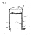
- this jacket 2 can have any desired cross-sectional shapes within the scope of the invention, for example — as FIG. 2 shows — also be cylindrical.
- FIG. 3 shows a variant of FIG. 1 and illustrates that the water-carrying water chamber 9, optionally in an annular configuration, can enclose a water-free space 12, which is arranged underneath a burner 11 and serves to supply this burner, to which the fuel supply line 13 is connected.
- the combustion chamber floor 7 is located in a plane 8 which is higher than the plane 14 of the lower edge of the outer wall 4.
- the space delimited by this outer wall 4 of the jacket 2 is by a flat plate 15 fastened to the edge completed, which together with the combustion chamber floor 7 delimits a water chamber 9, which connects the cavities 5 of the jacket 2 in a water-conducting manner.
- All water-carrying parts of the water heater i.e. the cavities 5 of the jacket 2, the water chamber 9 and possibly a heat exchanger accommodated in the combustion chamber 1, are connected to one another to form a circulation system, which may have a flow 16 and a return 17 (FIG. 1) in one Circulation heating can be included.
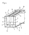
- FIG. 4 shows such a heat exchanger 18, which is accommodated in the combustion chamber 1 and, together with its flanks and the inner walls 3 of the jacket 2, limits exhaust gas ducts 19.
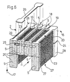
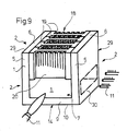
- FIG. 5 shows a sectional boiler that is composed, for example, of three boiler sections, namely one internal and two external boiler sections 20.
- the essentially plate-shaped boiler members 20 can be produced inexpensively from aluminum or another light metal alloy in the extrusion process and are braced together with their parallel flanks facing one another by connecting elements (not shown) to form a block and connected in a water-carrying manner via nipples 25.
- At least one of the internal boiler sections 20 is dimensioned shorter than the external boiler sections 20, which laterally delimit this combustion chamber 1 and form the jacket 2, and thus does not extend to, like the external boiler sections to the floor, but forms with its lower end the ceiling of the combustion chamber 1.
- the cavities 5 of the boiler sections 20 can be closed at their ends by end plates 26, the contour of which corresponds to the uniform profile of the boiler sections 20, for example lockable by welding or screwing.
- the inner regions 27 of the flanks of the boiler members 20, which are offset from the contact surfaces of the edge regions 28, are provided with projections 23, for example fins, which promote the heat exchange between the exhaust gases flowing upward from the combustion chamber 1 and the water contained in the cavities 5 of the boiler members 20.
- a sectional boiler according to the invention can thus be assembled within the scope of the invention in any size from an arbitrary number of uniformly profiled boiler sections of any variable length, the size of the combustion chamber 1 also being able to vary as desired.
- To manufacture the sectional boiler the required number of boiler sections 20 is cut to length from the strand in the lengths required in each case.
- the cavities 5 of these sections are closed by welding or screwing on the end plates 26 at both ends and such Art produced boiler members 20 are then connected to each other by means of the nipples 25 and braced to form a heating block.
- all of the boiler sections 20 are not only of identical design to one another, but are also of the same size.
- These boiler sections each consist of a web 21 which delimits the exhaust gas ducts 19 with its outer sides within the sectional boiler, and of two thickened edge areas 28 which form contact surfaces and which the web 21 connects to one another.
- the web 21 of the boiler member 20 encloses a cavity 5 which is parallel to the outer sides of the web 21 and open to one of the two end faces of the boiler member 20.
- the outer sides of the web 21 which serve to guide the exhaust gas are again provided in the inner regions 27 with projections 23, for example ribs, which promote heat exchange.
- two boiler sections 20 with the open end faces of their cavities 5 face upwards and the combustion chamber 1 is bridged next to one another between two outside boiler sections 20, the cavities 5 of which are used to form the combustion chamber 1 point downwards with their open end faces and are supplemented by the aligned cavities 5 below boiler elements 20 which form the water jacket 2 and whose cavities 5 are open upwards.
- the outer boiler sections 20, which are each aligned with one another, are connected to one another, e.g. by welding or gluing, firmly and sealingly connected in the butt joints 24.
- the remaining boiler members 20 can be clamped together to form a block by means of connecting elements (not shown).
- the cavities 5 of all boiler members 20 are to be connected to one another by nipples 25 which can be inserted into transverse bores and in this way form a water-carrying system within the boiler block, which system can be incorporated into a circulation heating system via a flow 16 and a return 17.
- the upwardly open cavities 5 of the boiler members 20 bridging the combustion chamber 1 can be closed by end plates 26, the contour of which corresponds to the uniform profile of the boiler members 20.
- the links of a sectional boiler according to FIG. 5 are very simple and accordingly inexpensive to produce by cutting extruded sections, but their use as end links is comparatively not economical because the share of these end links in the energy yield is relatively low.
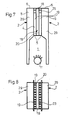
- boiler sections manufactured in the extrusion process only need to be used for the middle sections, but boiler sections with lower volume and lower efficiency for the outer links, according to FIGS. 7 and 8, one or more uniformly profiled boiler sections, i.e. those which can be produced by the extrusion process, are present on opposite sides Block made of steel end members 29 connected.
- a sectional kettle consists of the two steel end links 29 and a single central link 20, which is uniformly profiled and accordingly can be produced in an extrusion process, preferably from aluminum.
- This middle member 20 consists of a plate provided with rib-shaped extensions 23 and thereby limiting exhaust gas guides 19. Accordingly, the two steel end members 29 connect to the inner regions 27 of the flanks of the uniformly profiled boiler member 20, which are spaced apart by the extensions 23 and, together with the apexes of these extensions 23, limit the exhaust gas ducts 19.
- the central link 20 forming the exhaust gas guides 19 extends only over approximately half of the total height, namely only over the upper height range. and delimits with its underside the combustion chamber 1, in which an atmospheric burner 11 can be accommodated with an axial direction which runs in a vertical plane parallel to the vertical planes of the boiler members 20 and 29.
- the two end members 29 advantageously also take on the functions of a pressure plate. Due to the tapering of the end member 29 in the combustion chamber area, there is no need for an additional central member to create a combustion chamber 1 of sufficient width.
- steel end links 29 are connected to those sides of a link block consisting of a plurality of uniformly profiled boiler links 20, on which these boiler links 20 lie flush against one another with their edge regions 28.
- these uniformly profiled boiler sections 20, which can be produced by extrusion, only extend over the upper height region of the boiler and limit the combustion chamber 1 with their lower ends.
- a fan burner 11 with an axis perpendicular to the plane of the uniformly profiled boiler elements 20 can be arranged, or it can be inserted into this combustion chamber 1 through a recess 30 of one of the end elements 29, indicated by dash-dotted lines, of a group of atmospheric burners 11 extend.
- the outer boiler sections 20 of the section block for cooling the combustion chamber 1 can extend to the combustion chamber floor 7 and laterally limit the combustion chamber 1.
- the two steel end members 29 can be formed by the legs of a U-shaped member which, with its web, embodies the combustion chamber floor 7 and thus forms the water-carrying jacket 2 of the combustion chamber 1.
Landscapes
- Engineering & Computer Science (AREA)
- Physics & Mathematics (AREA)
- Thermal Sciences (AREA)
- Chemical & Material Sciences (AREA)
- Combustion & Propulsion (AREA)
- Mechanical Engineering (AREA)
- General Engineering & Computer Science (AREA)
- Instantaneous Water Boilers, Portable Hot-Water Supply Apparatuses, And Control Of Portable Hot-Water Supply Apparatuses (AREA)
- Steam Or Hot-Water Central Heating Systems (AREA)
- Addition Polymer Or Copolymer, Post-Treatments, Or Chemical Modifications (AREA)
- Gas Burners (AREA)
Applications Claiming Priority (8)
| Application Number | Priority Date | Filing Date | Title |
|---|---|---|---|
| AT534/87 | 1987-03-06 | ||
| AT53487A AT394265B (de) | 1987-03-06 | 1987-03-06 | Gliederkessel |
| AT533/87 | 1987-03-06 | ||
| AT53387A AT389754B (de) | 1987-03-06 | 1987-03-06 | Gliederkessel |
| AT672/87 | 1987-03-20 | ||
| AT67287A AT394901B (de) | 1987-03-20 | 1987-03-20 | Wasserheizer |
| AT23888A ATA23888A (de) | 1988-02-08 | 1988-02-08 | Gliederkessel |
| AT238/88 | 1988-02-08 |
Publications (3)
| Publication Number | Publication Date |
|---|---|
| EP0281125A2 true EP0281125A2 (fr) | 1988-09-07 |
| EP0281125A3 EP0281125A3 (en) | 1989-05-03 |
| EP0281125B1 EP0281125B1 (fr) | 1993-02-03 |
Family
ID=27421148
Family Applications (1)
| Application Number | Title | Priority Date | Filing Date |
|---|---|---|---|
| EP88103241A Expired - Lifetime EP0281125B1 (fr) | 1987-03-06 | 1988-03-03 | Chaudière à éléments |
Country Status (4)
| Country | Link |
|---|---|
| EP (1) | EP0281125B1 (fr) |
| AT (1) | ATE85418T1 (fr) |
| DE (2) | DE3877985D1 (fr) |
| ES (1) | ES2039487T3 (fr) |
Cited By (4)
| Publication number | Priority date | Publication date | Assignee | Title |
|---|---|---|---|---|
| EP0547641A1 (fr) * | 1991-12-16 | 1993-06-23 | Dejatech B.V. | Bruleur éventuellement intégré dans un échangeur de chaleur |
| NL1027438C2 (nl) * | 2004-11-08 | 2006-05-09 | Ontwikkelings En Produktiemij | Warmtewisselaar. |
| EP1933101A3 (fr) * | 2006-12-08 | 2012-09-05 | Vaillant GmbH | Echangeur thermique avec d'une chambre de combustion |
| US20190022807A1 (en) * | 2013-04-26 | 2019-01-24 | Dejatech Holding B.V. | Modular heat exchanger with sections interconnected by connectors |
Families Citing this family (2)
| Publication number | Priority date | Publication date | Assignee | Title |
|---|---|---|---|---|
| DE202015001228U1 (de) | 2015-02-19 | 2015-03-06 | Andreas Menakker | Bodendüse für einen Staubsauger |
| RU2688132C1 (ru) * | 2018-07-09 | 2019-05-17 | Алексей Леонидович Торопов | Котел для отопления |
Citations (7)
| Publication number | Priority date | Publication date | Assignee | Title |
|---|---|---|---|---|
| GB587662A (en) * | 1944-12-22 | 1947-05-01 | Gas Light & Coke Co | Improvements relating to domestic boilers |
| CH392011A (de) * | 1961-06-07 | 1965-05-15 | Oil Therm Ag | Heizkessel mit zusätzlichen Heizflächen |
| FR2211634A1 (fr) * | 1972-12-21 | 1974-07-19 | Beretta Costr Metall | |
| GB1370170A (en) * | 1973-03-15 | 1974-10-16 | Redfyre Ltd | Domestic water heating boiler |
| CH571203A5 (en) * | 1973-08-10 | 1975-12-31 | Roca Radiadores | Heat exchanger element for gas fired boilers - is a hollow rectangular cast iron plate with ribbed outer surface |
| FR2276541A1 (fr) * | 1974-06-28 | 1976-01-23 | Beondu Ag | Chaudiere de chauffage central en metal leger |
| EP0028046A1 (fr) * | 1979-10-25 | 1981-05-06 | Bretec Benelux B.V. | Chauffe-eau |
-
1988
- 1988-03-03 AT AT88103241T patent/ATE85418T1/de not_active IP Right Cessation
- 1988-03-03 ES ES198888103241T patent/ES2039487T3/es not_active Expired - Lifetime
- 1988-03-03 EP EP88103241A patent/EP0281125B1/fr not_active Expired - Lifetime
- 1988-03-03 DE DE8888103241T patent/DE3877985D1/de not_active Expired - Fee Related
- 1988-03-04 DE DE3807116A patent/DE3807116A1/de not_active Withdrawn
Patent Citations (7)
| Publication number | Priority date | Publication date | Assignee | Title |
|---|---|---|---|---|
| GB587662A (en) * | 1944-12-22 | 1947-05-01 | Gas Light & Coke Co | Improvements relating to domestic boilers |
| CH392011A (de) * | 1961-06-07 | 1965-05-15 | Oil Therm Ag | Heizkessel mit zusätzlichen Heizflächen |
| FR2211634A1 (fr) * | 1972-12-21 | 1974-07-19 | Beretta Costr Metall | |
| GB1370170A (en) * | 1973-03-15 | 1974-10-16 | Redfyre Ltd | Domestic water heating boiler |
| CH571203A5 (en) * | 1973-08-10 | 1975-12-31 | Roca Radiadores | Heat exchanger element for gas fired boilers - is a hollow rectangular cast iron plate with ribbed outer surface |
| FR2276541A1 (fr) * | 1974-06-28 | 1976-01-23 | Beondu Ag | Chaudiere de chauffage central en metal leger |
| EP0028046A1 (fr) * | 1979-10-25 | 1981-05-06 | Bretec Benelux B.V. | Chauffe-eau |
Cited By (4)
| Publication number | Priority date | Publication date | Assignee | Title |
|---|---|---|---|---|
| EP0547641A1 (fr) * | 1991-12-16 | 1993-06-23 | Dejatech B.V. | Bruleur éventuellement intégré dans un échangeur de chaleur |
| NL1027438C2 (nl) * | 2004-11-08 | 2006-05-09 | Ontwikkelings En Produktiemij | Warmtewisselaar. |
| EP1933101A3 (fr) * | 2006-12-08 | 2012-09-05 | Vaillant GmbH | Echangeur thermique avec d'une chambre de combustion |
| US20190022807A1 (en) * | 2013-04-26 | 2019-01-24 | Dejatech Holding B.V. | Modular heat exchanger with sections interconnected by connectors |
Also Published As
| Publication number | Publication date |
|---|---|
| EP0281125B1 (fr) | 1993-02-03 |
| DE3877985D1 (de) | 1993-03-18 |
| EP0281125A3 (en) | 1989-05-03 |
| ATE85418T1 (de) | 1993-02-15 |
| DE3807116A1 (de) | 1988-09-15 |
| ES2039487T3 (es) | 1993-10-01 |
Similar Documents
| Publication | Publication Date | Title |
|---|---|---|
| DE2942523A1 (de) | Elektrischer durchlauferhitzer | |
| DE3317162A1 (de) | Gasbeheizter oder oelbeheizter kessel zur warmwasser-, heisswasser- oder dampferzeugung | |
| EP0281125B1 (fr) | Chaudière à éléments | |
| EP0681156A1 (fr) | Echangeur de chaleur | |
| DE4309360C2 (de) | Heizungswärmetauscher für Kraftfahrzeuge | |
| EP0276408A2 (fr) | Chaudière à gaz atmosphérique | |
| DE19961638A1 (de) | Wärmetauscher | |
| DE3512891C2 (fr) | ||
| DE19808810C1 (de) | Hohlstein für den Gitterbesatz vom Kammern eines Glasschmelzofens und dessen Verwendung | |
| DE19713407B4 (de) | Atmosphärischer Gasbrenner | |
| DE2126226C3 (de) | Wärmeaustauscher | |
| AT394265B (de) | Gliederkessel | |
| AT389754B (de) | Gliederkessel | |
| DE1909128B2 (de) | Heizkörper | |
| AT394901B (de) | Wasserheizer | |
| DE3840980A1 (de) | Waermetauscher, insbesondere wasserheizer | |
| DE3724940C2 (fr) | ||
| WO1994017338A1 (fr) | Chaudiere de chauffage | |
| DE6609315U (de) | Radiatorsektion. | |
| AT395780B (de) | Wasserheizer | |
| DE1779505C3 (de) | Stahlgliederheizkörper | |
| AT396403B (de) | Brennkammerschacht | |
| DE2819145C2 (de) | Kamineinsatz | |
| DE2209389B2 (de) | Gliederheizkessel mit einem Rauchgaszug und einem Wasserkanal | |
| CH522134A (de) | Wasserdichte Verbindung von flächig aufeinanderliegenden Blechteilen und Verwendung derselben in einem Stahlblech-Plattenradiator |
Legal Events
| Date | Code | Title | Description |
|---|---|---|---|
| PUAI | Public reference made under article 153(3) epc to a published international application that has entered the european phase |
Free format text: ORIGINAL CODE: 0009012 |
|
| AK | Designated contracting states |
Kind code of ref document: A2 Designated state(s): AT BE CH DE ES FR GB GR IT LI LU NL SE |
|
| PUAL | Search report despatched |
Free format text: ORIGINAL CODE: 0009013 |
|
| AK | Designated contracting states |
Kind code of ref document: A3 Designated state(s): AT BE CH DE ES FR GB GR IT LI LU NL SE |
|
| 17P | Request for examination filed |
Effective date: 19891207 |
|
| 17Q | First examination report despatched |
Effective date: 19910111 |
|
| RAP1 | Party data changed (applicant data changed or rights of an application transferred) |
Owner name: VAILLANT GMBH Owner name: VAILLANT-SCHONEWELLE B.V. Owner name: VAILLANT LTD. Owner name: VAILLANT GES.M.B.H Owner name: VAILLANT S.A.R.L Owner name: N.V. VAILLANT S.A. Owner name: JOH. VAILLANT GMBH U. CO. |
|
| GRAA | (expected) grant |
Free format text: ORIGINAL CODE: 0009210 |
|
| AK | Designated contracting states |
Kind code of ref document: B1 Designated state(s): AT BE CH DE ES FR GB GR IT LI LU NL SE |
|
| PG25 | Lapsed in a contracting state [announced via postgrant information from national office to epo] |
Ref country code: SE Effective date: 19930203 Ref country code: GR Free format text: LAPSE BECAUSE OF FAILURE TO SUBMIT A TRANSLATION OF THE DESCRIPTION OR TO PAY THE FEE WITHIN THE PRESCRIBED TIME-LIMIT Effective date: 19930203 |
|
| REF | Corresponds to: |
Ref document number: 85418 Country of ref document: AT Date of ref document: 19930215 Kind code of ref document: T |
|
| PGFP | Annual fee paid to national office [announced via postgrant information from national office to epo] |
Ref country code: GB Payment date: 19930215 Year of fee payment: 6 |
|
| PGFP | Annual fee paid to national office [announced via postgrant information from national office to epo] |
Ref country code: BE Payment date: 19930302 Year of fee payment: 6 |
|
| REF | Corresponds to: |
Ref document number: 3877985 Country of ref document: DE Date of ref document: 19930318 |
|
| PG25 | Lapsed in a contracting state [announced via postgrant information from national office to epo] |
Ref country code: LU Free format text: LAPSE BECAUSE OF NON-PAYMENT OF DUE FEES Effective date: 19930331 |
|
| PGFP | Annual fee paid to national office [announced via postgrant information from national office to epo] |
Ref country code: NL Payment date: 19930331 Year of fee payment: 6 |
|
| GBT | Gb: translation of ep patent filed (gb section 77(6)(a)/1977) |
Effective date: 19930309 |
|
| ITF | It: translation for a ep patent filed |
Owner name: DE DOMINICIS & MAYER S.R.L. |
|
| PGFP | Annual fee paid to national office [announced via postgrant information from national office to epo] |
Ref country code: FR Payment date: 19930428 Year of fee payment: 6 |
|
| PGFP | Annual fee paid to national office [announced via postgrant information from national office to epo] |
Ref country code: ES Payment date: 19930430 Year of fee payment: 6 |
|
| ET | Fr: translation filed | ||
| REG | Reference to a national code |
Ref country code: ES Ref legal event code: FG2A Ref document number: 2039487 Country of ref document: ES Kind code of ref document: T3 |
|
| PLBE | No opposition filed within time limit |
Free format text: ORIGINAL CODE: 0009261 |
|
| STAA | Information on the status of an ep patent application or granted ep patent |
Free format text: STATUS: NO OPPOSITION FILED WITHIN TIME LIMIT |
|
| 26N | No opposition filed | ||
| PG25 | Lapsed in a contracting state [announced via postgrant information from national office to epo] |
Ref country code: GB Effective date: 19940303 |
|
| PG25 | Lapsed in a contracting state [announced via postgrant information from national office to epo] |
Ref country code: ES Free format text: LAPSE BECAUSE OF NON-PAYMENT OF DUE FEES Effective date: 19940304 |
|
| PG25 | Lapsed in a contracting state [announced via postgrant information from national office to epo] |
Ref country code: BE Effective date: 19940331 |
|
| BERE | Be: lapsed |
Owner name: S.A. VAILLANT N.V. Effective date: 19940331 |
|
| PG25 | Lapsed in a contracting state [announced via postgrant information from national office to epo] |
Ref country code: NL Effective date: 19941001 |
|
| GBPC | Gb: european patent ceased through non-payment of renewal fee |
Effective date: 19940303 |
|
| NLV4 | Nl: lapsed or anulled due to non-payment of the annual fee | ||
| PG25 | Lapsed in a contracting state [announced via postgrant information from national office to epo] |
Ref country code: FR Effective date: 19941130 |
|
| REG | Reference to a national code |
Ref country code: FR Ref legal event code: ST |
|
| PGFP | Annual fee paid to national office [announced via postgrant information from national office to epo] |
Ref country code: AT Payment date: 19980212 Year of fee payment: 11 |
|
| PGFP | Annual fee paid to national office [announced via postgrant information from national office to epo] |
Ref country code: DE Payment date: 19980317 Year of fee payment: 11 |
|
| PGFP | Annual fee paid to national office [announced via postgrant information from national office to epo] |
Ref country code: CH Payment date: 19980402 Year of fee payment: 11 |
|
| PG25 | Lapsed in a contracting state [announced via postgrant information from national office to epo] |
Ref country code: AT Free format text: LAPSE BECAUSE OF NON-PAYMENT OF DUE FEES Effective date: 19990303 |
|
| PG25 | Lapsed in a contracting state [announced via postgrant information from national office to epo] |
Ref country code: LI Free format text: LAPSE BECAUSE OF NON-PAYMENT OF DUE FEES Effective date: 19990331 Ref country code: CH Free format text: LAPSE BECAUSE OF NON-PAYMENT OF DUE FEES Effective date: 19990331 |
|
| REG | Reference to a national code |
Ref country code: ES Ref legal event code: FD2A Effective date: 19990503 |
|
| REG | Reference to a national code |
Ref country code: CH Ref legal event code: PL |
|
| PG25 | Lapsed in a contracting state [announced via postgrant information from national office to epo] |
Ref country code: DE Free format text: LAPSE BECAUSE OF NON-PAYMENT OF DUE FEES Effective date: 20000101 |
|
| PG25 | Lapsed in a contracting state [announced via postgrant information from national office to epo] |
Ref country code: IT Free format text: LAPSE BECAUSE OF NON-PAYMENT OF DUE FEES;WARNING: LAPSES OF ITALIAN PATENTS WITH EFFECTIVE DATE BEFORE 2007 MAY HAVE OCCURRED AT ANY TIME BEFORE 2007. THE CORRECT EFFECTIVE DATE MAY BE DIFFERENT FROM THE ONE RECORDED. Effective date: 20050303 |