EP0280857A2 - Sortiereinrichtung - Google Patents
Sortiereinrichtung Download PDFInfo
- Publication number
- EP0280857A2 EP0280857A2 EP19880100738 EP88100738A EP0280857A2 EP 0280857 A2 EP0280857 A2 EP 0280857A2 EP 19880100738 EP19880100738 EP 19880100738 EP 88100738 A EP88100738 A EP 88100738A EP 0280857 A2 EP0280857 A2 EP 0280857A2
- Authority
- EP
- European Patent Office
- Prior art keywords
- sorting device
- components
- screw
- sensor
- screws
- Prior art date
- Legal status (The legal status is an assumption and is not a legal conclusion. Google has not performed a legal analysis and makes no representation as to the accuracy of the status listed.)
- Granted
Links
Images

Classifications
-
- B—PERFORMING OPERATIONS; TRANSPORTING
- B07—SEPARATING SOLIDS FROM SOLIDS; SORTING
- B07C—POSTAL SORTING; SORTING INDIVIDUAL ARTICLES, OR BULK MATERIAL FIT TO BE SORTED PIECE-MEAL, e.g. BY PICKING
- B07C5/00—Sorting according to a characteristic or feature of the articles or material being sorted, e.g. by control effected by devices which detect or measure such characteristic or feature; Sorting by manually actuated devices, e.g. switches
- B07C5/04—Sorting according to size
- B07C5/08—Sorting according to size measured electrically or electronically
-
- B—PERFORMING OPERATIONS; TRANSPORTING
- B07—SEPARATING SOLIDS FROM SOLIDS; SORTING
- B07C—POSTAL SORTING; SORTING INDIVIDUAL ARTICLES, OR BULK MATERIAL FIT TO BE SORTED PIECE-MEAL, e.g. BY PICKING
- B07C5/00—Sorting according to a characteristic or feature of the articles or material being sorted, e.g. by control effected by devices which detect or measure such characteristic or feature; Sorting by manually actuated devices, e.g. switches
- B07C5/04—Sorting according to size
- B07C5/06—Sorting according to size measured mechanically
- B07C5/065—Sorting according to size measured mechanically with multiple measuring appliances adjusted according to different standards, for example length or thickness, which detect the shape of an object so that if it conforms to the standard set by the measuring appliance, it is removed from the conveyor, e.g. by means of a number of differently calibrated openings
-
- Y—GENERAL TAGGING OF NEW TECHNOLOGICAL DEVELOPMENTS; GENERAL TAGGING OF CROSS-SECTIONAL TECHNOLOGIES SPANNING OVER SEVERAL SECTIONS OF THE IPC; TECHNICAL SUBJECTS COVERED BY FORMER USPC CROSS-REFERENCE ART COLLECTIONS [XRACs] AND DIGESTS
- Y10—TECHNICAL SUBJECTS COVERED BY FORMER USPC
- Y10S—TECHNICAL SUBJECTS COVERED BY FORMER USPC CROSS-REFERENCE ART COLLECTIONS [XRACs] AND DIGESTS
- Y10S209/00—Classifying, separating, and assorting solids
- Y10S209/929—Fastener sorter
Definitions
- the invention relates to a sorting device according to the type of the main claim.
- a sorting device is already known in which the screws to be sorted are guided on a conveyor belt past an optoelectronic sensor, in particular a CCD sensor line equipped with photodiodes. With the help of a lamp, a shadow of the screw to be assessed is projected onto the sensor and this image is compared with the nominal dimensions. If the screw has a defect on the contour shown, it is blown off the conveyor belt by a nozzle belt.
- This sorting device has the disadvantage that only the projection shadow can be checked in a single plane for each measurement. Errors on the non-projected circumference, on the surface or inside (slot shape) cannot be detected. In addition, the measuring accuracy depends on the conveyor belt speed at the measuring point and on the stable position of the screw on the conveyor belt.
- the sorting device according to the invention with the characterizing features of the main claim has the advantage that the complete shape of the screws, both their shape and their dimensions, their surface quality and their internal shapes (slots, cracks) can be determined with great accuracy. Furthermore, the measurement result is independent of the conveyor speed of the conveyor. The measurement is not - as with optical measuring methods - affected by dirt. Temperature influences are also irrelevant. In addition, the sorting device is much cheaper than optical systems.
- the conveyor can consist, for example, of a simple rail with a liner conveyor. The reliability of the sorting device is considerably improved by the combination of mechanical and electrical measuring points.
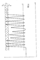
- Figure 1 shows a plan view of the entire sorting device.
- Figure 2 shows a cross section through the template 13 along the line II-II in Figure 1.
- Figure 3 shows a cross section through the shaft sensors 21 and 22.
- Figure 4 shows a measurement diagram of the shaft sensor.
- FIG. 5 shows a cross section through the head sensor 25.
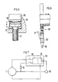
- a screw spindle is shown in FIG.
- Figure 7 shows the control loop of the sorting device.
- the sorting device is divided into two main parts, a conveyor pot 1 and a linear section 2 with the devices for screw detection and rejection.
- a separating device 3 and one or more screw spindles or a packaging machine (not shown) can be connected to the linear section 2.
- the well-known conveyor pot 1 takes up the screws, nails, head bolts or the like as bulk material and brings them in a row hanging from a rail 4.
- the rail 4 has a slot 5 through which the shafts of the screws, but not the heads, can pass.
- the rail 4 continues seamlessly in the rail 6 belonging to the linear path 2 with a slot 7 corresponding to the slot 5.
- the rail 6 is fixedly connected to a linear conveyor 8 known per se, which, by means of vibration, exerts as constant a linear conveying movement as possible on the screws 9.
- the slot 7 widens to a hole 10 which is slightly smaller than the head diameter of the screw 9 to be tested and fall through the screwing with too small a head diameter into a collecting container 11 for unusable screws.
- the screw 9 is further conveyed onto an interchangeable slide 12 and comes to a template 13.
- the screw geometries conveyed are incorporated into the template 13 in relation to head diameter A, shaft diameter B, head height C and shaft length D ( Figure 2).
- the template 13 consists of two halves 14 and 15 so that they can be attached to the rail 6, e.g. by screws, not shown, which reach through the template halves 14 and 15 and are screwed into the narrow sides of the rail 6. If one of the required dimensions is exceeded, the screw material jams in the template 13.
- the interchangeable slide 12 consists of two short rail sections 16 and 17, which are guided on a rod 18 and can be inserted alternately into a gap in the rail 6. Below the interchangeable slide 12 there is a collecting container 19, into which screws which are not removed from the linear section 2 by the interchangeable slide are located due to the conveying action also exerted on the rail sections 16 and 17 kung the linear conveyor 8 fall into it.
- the shuttle valve 12 receives its release signal from a control device 50, which will be described later.
- a traffic jam sensor 20 is arranged above the rail 6 and can detect whether there are screws under it or not.
- the traffic jam sensor 20 can operate according to mechanical, inductive, capacitive, piezoelectric, ultrasound or the eddy current principle or according to other principles and emits its signal to the electrical or pneumatic control device 50 (FIG. 7).
- the shaft sensor 21 Downstream of the accumulation sensor 20 is the shaft sensor 21, 22, which is inserted into recesses in the lateral flanks of the rail 6 (FIG. 3).
- the shaft sensor consists of two parts 21, 22, in each of which a coil 23, 24 is arranged.
- the coils preferably work according to the eddy current principle, the mode of operation of which is described in more detail in our application P 37 06 574.2 (filed on the same day) and with which surface defects can also be easily recognized.
- plates can also be contained in the shaft sensor and the measurement can be carried out capacitively.
- the following dimensions can be monitored with the aid of the shaft sensor 21, 22: shaft diameter, shaft length, thread defects, material defects such as cracks or cavities, and surface defects, for example poor surface treatment.
- a measurement signal results, which is shown in FIG. 4.
- the time t is plotted on the right, the height of the measurement signal upwards.
- the first three screws are within the tolerance range T and are OK.
- the next four screws are faulty and generate a measurement signal that is too low. Since errors can be compensated for with this measuring method, e.g. shaft diameter too small / thread missing or shaft too long / blowholes
- Some criteria were previously checked mechanically through the hole 10 and the template 13 and defective screws were sorted out.
- the test criteria to be monitored by the shaft sensor 21, 22 are therefore reduced to: shaft diameter too small, shaft length too short, thread, material and surface defects.
- the reliability of the sorting device can be increased even further by arranging several pairs of coils along the screw shaft.
- the shaft sensor 21, 22 registers both a counting pulse Z (FIG. 4) with a running nunmer, which is triggered each time a screw is passed, and the height of the shaft signal. If the measurement signal voltage lies outside the permissible tolerance range T, an error signal is assigned to the counting pulse of this screw and the screw is further conveyed to the separating block 30.
- a head sensor 25 arranged there also registers counting pulses with a serial number. If there appears a screw with a number to which an error signal is assigned, it is assigned to the feed slide 38 for defective screws.
- the signals are expediently processed by a controller developed for this purpose.
- the head sensor 25 is attached at a defined constant distance K above the rail 6 or the receiving fork 27 (FIG. 5).
- the coil 26 arranged in the head sensor 25 also works according to the eddy current principle according to our application P 37 06 574.2.
- the head sensor 25 detects the following errors: head height too low (head height too high is checked by template 13), head diameter too large (head diameter too small is also checked by template 13), incorrect slot design or force application surfaces (e.g. slot instead of Torx, not existing slot) and surface defect and also registers the counting pulse described above.
- Faulty screws produce - similar to the shaft sensor (FIG. 4) - a measuring signal that is too large or too small. This immediately causes the feed slide 38 for faulty screws to be actuated.
- the rail 6 ends shortly before the head sensor 25 and continues seamlessly in the receiving cable 27 of the cross slide 28, which is guided in a guide link 29 of the separating block 30.
- the guide link 29 is arranged obliquely to the sliding direction of the separating slide 31, which conveys the tested screws at right angles to the rail 6 to the feed hole 32.
- the displacement of the separating slide 31 is accomplished by a work unit, not shown, which is connected to the push rod 33.
- the push rod is in turn firmly connected to the separating slide 31.
- the cross slide 28 withdraws from the screw due to the guide link 29 (to the right in FIG. 1) and releases the screw head, so that the screw can fall freely through the hole 32 into one of the metering slides 34 to 38 shown .
- a total of twelve metering slides can be attached to plate 44.
- the metering slides have housings 39 in which pistons 40 are guided.
- the piston rods 41 of the pistons 40 carry head pieces 42 with bores 43.
- inlet hoses not shown in FIG. 1, are connected, through which the individual screws are conveyed either for packaging or via the inlet hoses 61 to screw spindles 60 shown in FIG.
- sensors 63 are e.g. in the jaws 62 of the screw spindles 60 Vortex sensors are used, which either output the signal "screw in the pliers" or “no screw in the pliers” to the separating device 3.
- the control device 50 (FIG. 7) has the signal from the sensor 20 as the input variable and the acknowledgment of the feedback from the feed pot 1 about its operating state (on-off).
- the sensor signal passes through a signal processor 51 and a timing control circuit 51 with two Exits. One of the outputs either switches the feed pot on or off, the other actuates the change-over slide 12 in such a way that the rail section 16 or 17 currently in the linear section 2 is disengaged and the other rail section 17 or 16 is inserted into the gap in the linear section 2.
Landscapes
- Engineering & Computer Science (AREA)
- Mechanical Engineering (AREA)
- Sorting Of Articles (AREA)
- Sampling And Sample Adjustment (AREA)
Abstract
- 2.1. Bei Montagesystemen mit automatischer Verschraubung ist einwandfreies Schraubenmaterial notwendig. Fehlerhafte Schrauben wurden bisher meist von Hand oder durch aufwendige optische Sortiereinrichtungen eliminiert. Die neue Sortiereinrichtung soll fehlerhafte Befestigungsbauteile zuverlässig und preiswert aussondern.
- 2.2. Fehlerhafte Bauteile werden durch eine Hintereinanderschaltung von mechanischen (10, 13) und nach dem Wirbelstromprinzip arbeitende elektrischen (21, 22, 25) Meßstationen erkannt und durch Auswurfeinrichtungen (10, 12, 3) von den maßhaltigen Befestigungsbauteilen abgesondert. Die mechanische Vorsortierung verhindert weitgehend die Kompensation von Abmessungsfehlern bei den elektrischen Meßstationen. Dadurch wird eine sehr hohe Zuverlässigkeit der Gesamtanlage erreicht.
- 2.3. Die Sortiereinrichtung eignet sich bei automatischen Montagesystemen zur Zuführung von Schrauben an Schraubspindeln. Sie kann auch z.B. bei Schraubenherstellern zur Bereitstellung einwandfreien Schraubenmaterials eingesetzt werden.
Description
- Die Erfindung geht aus von einer Sortiereinrichtung nach der Gattung des Hauptanspruchs. Es ist bereits eine Sortiereinrichtung bekannt, bei der die zu sortierenden Schrauben auf einem Förderband an einem optoelektronischen Sensor, speziell einer mit Fotodioden bestückten CCD-Sensorzeile vorbeigeführt werden. Dabei wird mit Hilfe einer Lampe ein Schatten der zu beurteilenden Schraube auf den Sensor projiziert und dieses Bild mit den Sollmaßen verglichen. Wenn die Schraube an ihrer abgebildeten Kontur einen Fehler aufweist, wird sie durch ein Düsenband vom Förderband abgeblasen. Diese Sortiereinrichtung hat den Nachteil, daß bei jeder Messung nur der Projektionsschatten in einer einzigen Ebene überprüft werden kann. Fehler am nicht projizierten Umfang, an der Oberfläche oder im Inneren (Schlitzform) können nicht erkannt werden. Außerdem ist die Meßgenauigkeit von der Förderbandgeschwindigkeit am Meßpunkt und von der stabilen Lage der Schraube auf dem Förderband abhängig.
- Die erfindungsgemäße Sortiereinrichtung mit den kennzeichnenden Merkmalen des Hauptanspruchs hat demgegenüber den Vorteil, daß die vollständige Gestalt der Schrauben, sowohl deren Form als auch deren Abmessungen, deren Oberflächenbeschaffenheit sowie deren innere Formen (Schlitze, Risse), mit großer Genauigkeit erfaßt werden können. Weiter ist das Meßergebnis unabhängig von der Fördergeschwindigkeit der Fördereinrichtung. Die Messung wird nicht - wie bei optischen Meßverfahren - von Schmutzteilen beeinträchtigt. Auch Temperatureinflüsse sind unerheblich. Außerdem ist die Sortiereinrichtung gegenüber optischen Systemen wesentlich billiger. Die Fördereinrichtung kann beispielsweise aus einer einfachen Schiene mit einem Linerförderer bestehen. Durch die Kombination von mechanischen und elektrischen Meßstellen wird die Zuverlässigkeit der Sortiereinrichtung erheblich verbessert.
- Ein Ausführungsbeispiel der Sortiereinrichtung ist in der Zeichnung dargestellt und in der nachfolgenden Beschreibung näher erläutert. Figur 1 zeigt eine Draufsicht auf die gesamte Sortiereinrichtung. Figur 2 zeigt einen Querschnitt durch die Schablone 13 gemäß Linie II-II in Figur 1. Figur 3 zeigt einen Querschnitt durch die Schaftsensoren 21 und 22. In Figure 4 ist ein Meßdiagramm des Schaftsensors dargestellt. Figur 5 zeigt einen Querschnitt durch den Kopfsensor 25. In Figur 6 ist eine Schraubspindel gezeigt. Figur 7 zeigt den Regelkreis der Sortiereinrichtung.
- Die Sortiereinrichtung ist in zwei Hauptteile gegliedert, einen Fördertopf 1 und eine Linearstrecke 2 mit den Einrichtungen zur Schraubenerkennung und Aussonderung. An die Linearstrecke 2 kann sich eine Vereinzelungseinrichtung 3 und ein oder mehrere Schraubspindeln oder eine nicht gezeigte Verpackungsmaschine anschließen.
- Der an sich bekannte Fördertopf 1 nimmt die Schrauben, Nägel, Kopfbolzen oder ähnliches als Schüttgut auf und bringt sie in Reihe an einer Schiene 4 hängend aus. Die Schiene 4 weist einen Schlitz 5 auf, durch den die Schäfte der Schrauben, nicht aber die Köpfe hindurchtreten können. Die Schiene 4 setzt sich übergangslos in der zur Linearstrecke 2 gehörigen Schiene 6 mit einem dem Schlitz 5 entsprechenden Schlitz 7 fort. Die Schiene 6 ist mit einem an sich bekannten Linearförderer 8 fest verbunden, der durch Vibration eine möglichst konstante geradlinige Förderbewegung auf die Schrauben 9 ausübt.
- Der Schlitz 7 erweitert sich zu einem Loch 10, das geringfügig kleiner als der Kopfdurchmesser der zu prüfenden Schraube 9 ist und durch das Schrauben mit zu kleinem Kopfdurchmesser in einen Auffangbehälter 11 für nicht brauchbare Schrauben fallen.
- Ist der Kopfdurchmesser jedoch nicht zu klein, so wird die Schraube 9 weiter auf einen Wechselschieber 12 gefördert und kommt an eine Schablone 13. In die Schablone 13 sind die geförderten Schraubengeometrien in bezug auf Kopfdurchmesser A, Schaftdurchmesser B, Kopfhöhe C und Schaftlänge D eingearbeitet (Figur 2). Die Schablone 13 besteht aus zwei Hälften 14 und 15, um sie an die Schiene 6 anbauen zu können, z.B. durch nicht gezeigte Schrauben, die die Schablonenhälften 14 und 15 durchgreifen und in die Schmalseiten der Schiene 6 eingeschraubt sind. Wird eines der geforderten Maße überschritten, so staut sich das Schraubenmaterial en der Schablone 13.
- Der Wechselschieber 12 besteht aus zwei kurzen Schienenstücken 16 und 17, die an einer Stange 18 geführt, abwechselnd in eine Lücke der Schiene 6 einrückbar sind. Unterhalb des Wechselschiebers 12 befindet sich ein Auffangbehälter 19, in den von dem Wechselschieber aus der Linearstrecke 2 entnommene nicht maßhaltige Schrauben aufgrund der auch auf die Schienenstücke 16 und 17 ausgeübte Förderwir kung des Linearförderers 8 hineinfallen. Der Wechselschieber 12 erhält sein Ausrücksignal von einer Regeleinrichtung 50, die später noch beschrieben wird.
- Im weiteren Verlauf der Linearstrecke 2 ist überhalb der Schiene 6 ein Stausensor 20 angeordnet, der erkennen kann, ob sich unter ihm Schrauben befinden oder nicht. Der Stausensor 20 kann nach mechanischem, induktivem, kapazitiven, piezoelektrischem, dem Ultraschall oder dem Wirbelstromprinzip oder nach anderen Prinzipien arbeiten und gibt sein Signal an die elektrische oder pneumatische Regeleinrichtung 50 (Figur 7) ab.
- In Förderrichtung dem Stausensor 20 nachgeordnet ist der Schaftsensor 21, 22, der in Aussparungen der seitlichen Flanken der Schiene 6 eingesetzt ist (Figur 3). Der Schaftsensor besteht aus zwei Teilen 21, 22, in denen jeweils eine Spule 23, 24 angeordnet ist. Die Spulen arbeiten vorzugsweise nach dem Wirbelstromprinzip, dessen Wirkungsweise in unserer (am gleichen Tag eingereichten) Anmeldung P 37 06 574.2 genauer beschrieben ist und womit auch Oberflächenfehler gut erkannt werden können. Statt der Spulen 23, 24 können aber auch Platten in dem Schaftsensor enthalten sein und die Messung kapazitiv vorgenommen werden.
- Mit Hilfe des Schaftsensors 21, 22 lassen sich folgende Abmessungen überwachen: Schaftdurchmesser, Schaftlänge, Gewindefehler, Materialfehler wie Risse oder Lunker, und Oberflächenfehler, z.B. mangelhafte Oberflächenbehandlung. Es ergibt sich ein Meßsignal, welches in Figur 4 dargestellt ist. Nach rechts ist die Zeit t aufgetragen, nach oben die Höhe des Meßsignals. Die ersten drei Schrauben liegen innerhalb der Toleranzbreite T und sind in Ordnung. Die nächsten vier Schrauben sind fehlerhaft und erzeugen ein zu geringes Meßsignal. Da sich bei dieser Meßmethode Fehler kompensieren können, z.B. Schaftdurchmesser zu klein/Gewinde fehlt oder Schaft zu lang/Lunker wurden einige Kriterien bereits vorher mechanisch durch das Loch 10 und die Schablone 13 geprüft und fehlerhafte Schrauben aussortiert. Die von dem Schaftsensor 21, 22 zu überwachenden Prüfkriterien verringern sich also auf: Schaftdurchmesser zu klein, Schaftlänge zu kurz, Gewinde-, Material- und Oberflächenfehler. Durch Anordnung mehrerer Spulenpaare untereinander entlang des Schraubenschaftes läßt sich die Zuverlässigkeit der Sortiereinrichtung noch steigern.
- Der Schaftsensor 21, 22 registriert sowohl einen Zählimpuls Z (Figur 4) mit laufender Nunmer, der bei jeder vorbeigeführten Schraube ausgelöst wird, als auch die Höhe des Schaftsignals. Liegt die Meßsignalspannung außerhalb der zulässigen Toleranzbreite T so wird dem Zählimpuls dieser Schraube ein Fehlersignal zugeordnet und die Schraube wird weiter bis zum Vereinzelungsblock 30 gefördert. Ein dort angeordneter Kopfsensor 25 registriert ebenfalls Zählimpulse mit laufender Nummer. Erscheint dort eine Schraube mit einer Nummer, der ein Fehlersignal zugeordnet ist, wird sie dem Zuteilschieber 38 für fehlerhafte Schrauben zugeteilt. Zweckmäßigerweise werden die Signale durch eine dafür entwickelte Steuerung verarbeitet.
- Der Kopfsensor 25 ist in einem definierten konstanten Abstand K oberhalb der Schiene 6 bzw. der Aufnahmegabel 27 angebracht (Figur 5). Die in dem Kopfsensor 25 angeordnete Spule 26 arbeitet ebenfalls nach dem Wirbelstromprinzip gemäß unserer Anmeldung P 37 06 574.2. Der Kopfsensor 25 erkennt folgende Fehler: Kopfhöhe zu niedrig (Kopfhöhe zu hoch wird durch die Schablone 13 geprüft), Kopfdurch messer zu groß (Kopfdurchmesser zu klein wird ebenfalls durch die Schablone 13 geprüft, fehlerhafte Schlitzausprägung bzw. Kraftangriffsflächen (z.B. Schlitz statt Torx, nicht vorhandener Schlitz) und Oberflächenfehler. Außerdem registriert er den oben beschriebenen Zählimpuls. Fehlerhafte Schrauben erzeugen - ähnlich wie bei dem Schaftsensor (Figur 4) - ein zu großes oder zu kleines Meßsignal. Dies bewirkt sofort die Betätigung des Zuteilschiebers 38 für fehlerhafte Schrauben.
- Die Schiene 6 endet kurz vor dem Kopfsensor 25 und setzt sich übergangslos in der Aufnahmekabel 27 des Querschiebers 28 fort, der in einer Führungskulisse 29 des Vereinzelungsblocks 30 geführt ist. Die Führungskulisse 29 ist schräg zur Schieberichtung des Vereinzelungsschiebers 31 angeordnet, der die geprüften Schrauben rechtwinklig zur Schiene 6 zu dem Zuteilloch 32 befördert. Die Verschiebung des Vereinzelungsschiebers 31 wird durch ein nicht gezeigtes Arbeitsaggregat bewerkstelligt, das mit der Schubstange 33 verbunden ist. Die Schubstange ist wiederum fest mit dem Vereinzelungsschieber 31 verbunden. Während der Verschiebung des Vereinzelungsschiebers 31 weicht der Querschieber 28 wegen der Führungskulisse 29 von der Schraube zurück (in Figur 1 nach rechts) und gibt den Schraubenkopf frei, so daß die Schraube frei durch das Zuteilloch 32 in einen der gezeigten Zuteilschieber 34 bis 38 fallen kann. Insgbesamt sind zwölf Zuteilschieber an die Platte 44 anbaubar.
- Die Zuteilschieber weisen Gehäuse 39 auf, in denen Kolben 40 geführt sind. Die Kolbenstangen 41 der Kolben 40 tragen Kopfstücke 42 mit Bohrungen 43. Unterhalb der Bohrungen 43 sind in Figur 1 nicht gezeigte Zublasschläuche angeschlossen, durch die hindurch die vereinzelten Schrauben entweder zur Verpackung oder über die Zublasschläuche 61 zu in Figur 6 dargestellten Schraubspindeln 60 gefördert werden.
- Zur Steuerung der Vereinzelungseinrichtung 3 sind in den Zangenbacken 62 der Schraubspindeln 60 Sensoren 63 z.B. Wirbelsensoren eingesetzt, die entweder das Signal "Schraube in der Zange" oder "keine Schraube in der Zange" an die Vereinzelungseinrichtung 3 abgeben.
- Die Regeleinrichtung 50 (Figur 7) hat als Eingangsgröße das Signal des Sensor 20 und als Quittung die Rückmeldung der Fördertopfes 1 über dessen Betriebszustand (Ein-Aus). Das Sensorsignal durchläuft einen Signalaufbereitung 51 und eine Zeitsteuerschaltung 51 mit zwei Ausgängen. Einer der Ausgänge schaltet den Fördertopf entweder ein oder aus, der andere betätigt den Wechselschieber 12 in der Weise, daß das gerade in der Linearstrecke 2 befindliche Schienenstück 16 oder 17 ausgerückt und das andere Schienenstück 17 oder 16 in die Lücke der Linearstrecke 2 eingerückt wird.
Claims (21)
Applications Claiming Priority (2)
| Application Number | Priority Date | Filing Date | Title |
|---|---|---|---|
| DE19873706575 DE3706575A1 (de) | 1987-02-28 | 1987-02-28 | Sortiereinrichtung |
| DE3706575 | 1987-02-28 |
Publications (3)
| Publication Number | Publication Date |
|---|---|
| EP0280857A2 true EP0280857A2 (de) | 1988-09-07 |
| EP0280857A3 EP0280857A3 (en) | 1989-08-30 |
| EP0280857B1 EP0280857B1 (de) | 1993-11-18 |
Family
ID=6322043
Family Applications (1)
| Application Number | Title | Priority Date | Filing Date |
|---|---|---|---|
| EP88100738A Expired - Lifetime EP0280857B1 (de) | 1987-02-28 | 1988-01-20 | Sortiereinrichtung |
Country Status (4)
| Country | Link |
|---|---|
| US (1) | US4905842A (de) |
| EP (1) | EP0280857B1 (de) |
| DE (2) | DE3706575A1 (de) |
| ES (1) | ES2046993T3 (de) |
Cited By (3)
| Publication number | Priority date | Publication date | Assignee | Title |
|---|---|---|---|---|
| WO2008071204A1 (en) * | 2006-12-12 | 2008-06-19 | Montanuniversität Leoben | System and method for the defect analysis of workpieces |
| CN114460320A (zh) * | 2022-04-14 | 2022-05-10 | 深圳市帝迈生物技术有限公司 | 样本分析仪及其样本检测流程 |
| CN120861419A (zh) * | 2025-09-29 | 2025-10-31 | 联钢精密科技(中国)有限公司 | 一种具有防划伤功能的螺母检测分料装置 |
Families Citing this family (25)
| Publication number | Priority date | Publication date | Assignee | Title |
|---|---|---|---|---|
| DE3827337A1 (de) * | 1988-08-12 | 1990-02-15 | Bosch Gmbh Robert | Sortiereinrichtung |
| DE4002992C2 (de) * | 1990-02-01 | 1994-12-08 | Horst Linnerbauer | Verfahren zum Vereinzeln und Ausrichten von Werkstücken und Bauteilen sowie zugehörige Zuführvorrichtung |
| US5165551A (en) * | 1990-03-30 | 1992-11-24 | Automation Associates, Inc. | Apparatus and method for detecting defects in an article |
| US5777246A (en) * | 1995-12-01 | 1998-07-07 | The Boeing Company | Fastener measurement system |
| US5823356A (en) * | 1996-04-25 | 1998-10-20 | Ajax Metal Processing, Inc. | Apparatus and method for insepcting threaded members |
| US6004215A (en) * | 1997-11-05 | 1999-12-21 | L & M Machinery & Manufacturing | Fastener forming machine |
| DE20015407U1 (de) * | 2000-09-06 | 2002-01-17 | Emhart Inc., Newark, Del. | Vereinzelungsvorrichtung |
| US6787724B2 (en) * | 2001-08-24 | 2004-09-07 | Attica Automation | Sorting machine |
| US20050174567A1 (en) * | 2004-02-09 | 2005-08-11 | Mectron Engineering Company | Crack detection system |
| US7416086B2 (en) * | 2004-05-03 | 2008-08-26 | Acument Intellectual Properties Llc | In-line sorter for fasteners |
| TWM269975U (en) * | 2004-05-21 | 2005-07-11 | Aerser Internat Co Ltd | Screw inspection machinery |
| DE102004030667B4 (de) * | 2004-06-24 | 2017-10-19 | Gassner Ges.M.B.H. | Sortiergerät |
| DE202004017425U1 (de) * | 2004-11-10 | 2005-01-13 | Böllhoff Verbindungstechnik GmbH | Mess- und Sortiervorrichtung |
| US20080174107A1 (en) * | 2007-01-23 | 2008-07-24 | Burl Jordan | System and Method for Identifying Irrigation Fittings |
| US7491319B1 (en) * | 2008-03-17 | 2009-02-17 | Te Hung En Enterprise Co., Ltd. | Inspecting apparatus with eddy current inspection |
| US8204294B2 (en) * | 2009-11-25 | 2012-06-19 | Toyota Motor Engineering & Manufacturing North America, Inc. | Systems and methods for detecting defects in coatings utilizing color-based thermal mismatch |
| US8789446B1 (en) | 2011-06-28 | 2014-07-29 | Western Digital Technologies, Inc. | Screw feeding apparatus to deliver a screw from a vibrating rail to a screw guide tube |
| US9150360B1 (en) | 2013-05-16 | 2015-10-06 | Western Digital Technologies, Inc. | Mechanism to deliver fastener vertically |
| CN104215190A (zh) * | 2014-08-13 | 2014-12-17 | 常州精研科技有限公司 | 手机微小零部件的内螺纹检测装置 |
| CN104624521A (zh) * | 2015-03-02 | 2015-05-20 | 上海众源燃油分配器制造有限公司 | 一种螺母螺纹及裂缝自动检测设备 |
| US9731328B2 (en) * | 2015-08-03 | 2017-08-15 | Linear Group Services, LLC | Inspection and sorting machine |
| CN106066362A (zh) * | 2016-05-24 | 2016-11-02 | 海盐正联检测技术有限公司 | 螺栓紧固件自动化硬度检测和筛选打包系统 |
| JP6705983B2 (ja) * | 2016-07-28 | 2020-06-03 | 青山 省司 | 頭部付き軸状部品の選別構造部 |
| DE102016124694B4 (de) * | 2016-12-16 | 2020-06-10 | Peter Müller | Fügeelemente-Bereitstellungsvorrichtung sowie zugehörige Robotervorrichtung |
| CN118954030B (zh) * | 2024-07-29 | 2026-01-02 | 中交一公局第三工程有限公司 | 一种盾构隧道连续与垂直皮带机相结合的智能出渣系统 |
Family Cites Families (20)
| Publication number | Priority date | Publication date | Assignee | Title |
|---|---|---|---|---|
| US2464449A (en) * | 1949-03-15 | Johnston | ||
| US2310661A (en) * | 1940-05-14 | 1943-02-09 | Glenn L Martin Co | Sorting machine |
| US3091332A (en) * | 1958-09-25 | 1963-05-28 | Aluminium Lab Ltd | Inspecting or sorting apparatus |
| US3392829A (en) * | 1966-01-10 | 1968-07-16 | Continental Can Co | Container locating and vacuum sensing system |
| US3455446A (en) * | 1967-09-05 | 1969-07-15 | Burton S Seafood Inc | Apparatus and method for advancing objects to gauging slots |
| US3539006A (en) * | 1968-05-22 | 1970-11-10 | Lamson & Sessions Co | Method and apparatus for inspecting annular articles |
| FR2071351A5 (de) * | 1969-12-24 | 1971-09-17 | Lamson Sessions Co | |
| US3709328A (en) * | 1970-08-12 | 1973-01-09 | Reich Maschf Gmbh Karl | Fastener sorting apparatus |
| US3650397A (en) * | 1970-11-19 | 1972-03-21 | Sensors Inc | System for inspecting and classifying objects such as screws, bolts and the like while in motion |
| US4174028A (en) * | 1974-06-13 | 1979-11-13 | Amerace Corporation | Method and apparatus for orienting and storing similar articles |
| US4002560A (en) * | 1975-07-24 | 1977-01-11 | Grantham Frederick W | Automatic article sorting apparatus |
| DE2609081C3 (de) * | 1976-03-05 | 1979-04-12 | Maschinenfabrik Lorenz Ag, 7505 Ettlingen | Vorrichtung zum Sortieren von Gegenständen |
| US4410078A (en) * | 1978-01-05 | 1983-10-18 | The Continental Group, Inc. | Article density sensing |
| US4341311A (en) * | 1980-08-25 | 1982-07-27 | Deere & Company | Method and apparatus for sorting rivets |
| US4454947A (en) * | 1981-12-07 | 1984-06-19 | Olin Corporation | Product inspection and ejection system |
| GB2111213A (en) * | 1981-12-09 | 1983-06-29 | Neuss Schraubenwerk | Method and apparatus for sorting screws |
| US4457622A (en) * | 1982-01-27 | 1984-07-03 | Nhk Spring Co., Ltd. | Screw inspection device |
| US4487321A (en) * | 1982-07-01 | 1984-12-11 | Diamond Automations, Inc. | Article coding and separating system |
| US4576286A (en) * | 1983-06-27 | 1986-03-18 | Cochlea Corporation | Parts sorting systems |
| US4602711A (en) * | 1984-06-15 | 1986-07-29 | Wullenwaber Robert W | Apparatus for feeding cylindrical workpieces to a workplace |
-
1987
- 1987-02-28 DE DE19873706575 patent/DE3706575A1/de not_active Withdrawn
-
1988
- 1988-01-12 US US07/143,445 patent/US4905842A/en not_active Expired - Fee Related
- 1988-01-20 ES ES88100738T patent/ES2046993T3/es not_active Expired - Lifetime
- 1988-01-20 DE DE88100738T patent/DE3885629D1/de not_active Expired - Fee Related
- 1988-01-20 EP EP88100738A patent/EP0280857B1/de not_active Expired - Lifetime
Cited By (4)
| Publication number | Priority date | Publication date | Assignee | Title |
|---|---|---|---|---|
| WO2008071204A1 (en) * | 2006-12-12 | 2008-06-19 | Montanuniversität Leoben | System and method for the defect analysis of workpieces |
| CN114460320A (zh) * | 2022-04-14 | 2022-05-10 | 深圳市帝迈生物技术有限公司 | 样本分析仪及其样本检测流程 |
| CN120861419A (zh) * | 2025-09-29 | 2025-10-31 | 联钢精密科技(中国)有限公司 | 一种具有防划伤功能的螺母检测分料装置 |
| CN120861419B (zh) * | 2025-09-29 | 2025-12-09 | 联钢精密科技(中国)有限公司 | 一种具有防划伤功能的螺母检测分料装置 |
Also Published As
| Publication number | Publication date |
|---|---|
| ES2046993T3 (es) | 1994-02-16 |
| EP0280857B1 (de) | 1993-11-18 |
| DE3706575A1 (de) | 1988-09-08 |
| US4905842A (en) | 1990-03-06 |
| DE3885629D1 (de) | 1993-12-23 |
| EP0280857A3 (en) | 1989-08-30 |
Similar Documents
| Publication | Publication Date | Title |
|---|---|---|
| EP0280857B1 (de) | Sortiereinrichtung | |
| EP0270133B1 (de) | Teilezuführeinrichtung | |
| DE602004004249T2 (de) | Verfahren zum detektieren und beseitigen fehlerhafter zigaretten | |
| EP3512788A1 (de) | Verfahren und vorrichtung zum sortieren von scheibenfoermigen objekten | |
| EP0528197B1 (de) | Verfahren und Vorrichtung zur Inspektion von Tabletten | |
| EP0461616A2 (de) | Verfahren und Vorrichtung zum Sortieren von Altglas | |
| DE4312550C1 (de) | Vorrichtung zur Bewertung von sich fortbewegenden Objekten | |
| DE19642793A1 (de) | Verfahren und Anordnung zum Prüfen von Zigaretten in definierten Zigarettenformationen | |
| DE4324109B4 (de) | Gewindeprüfvorrichtung | |
| DE3730307C2 (de) | Zuführeinrichtung mit Vorratskammern | |
| DE4404912B4 (de) | Verfahren und Vorrichtung zum Überprüfen der genauen Positionierung des Filterpapiers von Zigaretten | |
| EP0282728A2 (de) | Verfahren und Vorrichtung zum Prüfen von Packungen | |
| DE202004016049U1 (de) | Testsystem für Solarzellen | |
| EP0893516A1 (de) | Verfahren und Vorrichtung zum Identifizieren der lagebezogenen Herkunft von Fremdstoffen in Faserballen, insbesondere Baumwollballen | |
| DE602004011268T2 (de) | Verfahren zur definition, verfolgung und entfernung eines teils von fehlerhaften stangenförmigen elementen, die über eine tabakindustrie-fertigungsstrassenfördereinrichtung befördert werden, und system, das die definition, verfolgung und entfernung eines teils von fehlerhaften stangenförmigen elementen von der fördereinrichtung an der tabakindustrie-fertigungsstrasse gestattet | |
| DE2837362C2 (de) | Einrichtung zum selbsttätigen Prüfen viereckiger Bleche längs eines Transportsystems | |
| DE3007540A1 (de) | Vorrichtung zum pruefen und aussortieren von fremdflaschen | |
| DE3624419A1 (de) | Vorrichtung zur objektkontrolle | |
| EP0303084A2 (de) | Verfahren und Vorrichtung zur Messung von Gegenständen auf einer Förderstrecke | |
| DE102025106364B3 (de) | Messgerät zur Ermittlung einer Zuführungsgeschwindigkeit eines Verbindungselements, Messgerätmontagesatz sowie Verfahren zum Verwenden eines Messgeräts | |
| GB1604842A (en) | Apparatus for determining a dimension of an article | |
| DE2410648C3 (de) | Verfahren zur Feststellung und zur Eliminierung von Zählfehlern | |
| DE2649496C3 (de) | Vorrichtung zur Prüfung der richtigen Lage und Zahl von in Magazinen in Reihen hintereinander gelagerten Bauelementen | |
| DE19633326A1 (de) | Verfahren und Vorrichtung zur Kontrolle der Qualität von Werkstücken | |
| DE3827337A1 (de) | Sortiereinrichtung |
Legal Events
| Date | Code | Title | Description |
|---|---|---|---|
| PUAI | Public reference made under article 153(3) epc to a published international application that has entered the european phase |
Free format text: ORIGINAL CODE: 0009012 |
|
| AK | Designated contracting states |
Kind code of ref document: A2 Designated state(s): DE ES FR GB IT SE |
|
| PUAL | Search report despatched |
Free format text: ORIGINAL CODE: 0009013 |
|
| AK | Designated contracting states |
Kind code of ref document: A3 Designated state(s): DE ES FR GB IT SE |
|
| 17P | Request for examination filed |
Effective date: 19900206 |
|
| RAP3 | Party data changed (applicant data changed or rights of an application transferred) |
Owner name: ROBERT BOSCH GMBH |
|
| 17Q | First examination report despatched |
Effective date: 19920403 |
|
| GRAA | (expected) grant |
Free format text: ORIGINAL CODE: 0009210 |
|
| AK | Designated contracting states |
Kind code of ref document: B1 Designated state(s): DE ES FR GB IT SE |
|
| GBT | Gb: translation of ep patent filed (gb section 77(6)(a)/1977) |
Effective date: 19931117 |
|
| ET | Fr: translation filed | ||
| REF | Corresponds to: |
Ref document number: 3885629 Country of ref document: DE Date of ref document: 19931223 |
|
| PGFP | Annual fee paid to national office [announced via postgrant information from national office to epo] |
Ref country code: ES Payment date: 19940117 Year of fee payment: 7 |
|
| ITF | It: translation for a ep patent filed | ||
| REG | Reference to a national code |
Ref country code: ES Ref legal event code: FG2A Ref document number: 2046993 Country of ref document: ES Kind code of ref document: T3 |
|
| PLBE | No opposition filed within time limit |
Free format text: ORIGINAL CODE: 0009261 |
|
| STAA | Information on the status of an ep patent application or granted ep patent |
Free format text: STATUS: NO OPPOSITION FILED WITHIN TIME LIMIT |
|
| 26N | No opposition filed | ||
| PG25 | Lapsed in a contracting state [announced via postgrant information from national office to epo] |
Ref country code: ES Free format text: LAPSE BECAUSE OF NON-PAYMENT OF DUE FEES Effective date: 19950121 |
|
| EAL | Se: european patent in force in sweden |
Ref document number: 88100738.9 |
|
| PGFP | Annual fee paid to national office [announced via postgrant information from national office to epo] |
Ref country code: GB Payment date: 19971219 Year of fee payment: 11 |
|
| PGFP | Annual fee paid to national office [announced via postgrant information from national office to epo] |
Ref country code: FR Payment date: 19980120 Year of fee payment: 11 |
|
| PGFP | Annual fee paid to national office [announced via postgrant information from national office to epo] |
Ref country code: SE Payment date: 19980122 Year of fee payment: 11 |
|
| PGFP | Annual fee paid to national office [announced via postgrant information from national office to epo] |
Ref country code: DE Payment date: 19980320 Year of fee payment: 11 |
|
| PG25 | Lapsed in a contracting state [announced via postgrant information from national office to epo] |
Ref country code: GB Free format text: LAPSE BECAUSE OF NON-PAYMENT OF DUE FEES Effective date: 19990120 |
|
| PG25 | Lapsed in a contracting state [announced via postgrant information from national office to epo] |
Ref country code: SE Free format text: LAPSE BECAUSE OF NON-PAYMENT OF DUE FEES Effective date: 19990121 |
|
| REG | Reference to a national code |
Ref country code: ES Ref legal event code: FD2A Effective date: 19990301 |
|
| GBPC | Gb: european patent ceased through non-payment of renewal fee |
Effective date: 19990120 |
|
| PG25 | Lapsed in a contracting state [announced via postgrant information from national office to epo] |
Ref country code: FR Free format text: LAPSE BECAUSE OF NON-PAYMENT OF DUE FEES Effective date: 19990930 |
|
| PG25 | Lapsed in a contracting state [announced via postgrant information from national office to epo] |
Ref country code: DE Free format text: LAPSE BECAUSE OF NON-PAYMENT OF DUE FEES Effective date: 19991103 |
|
| REG | Reference to a national code |
Ref country code: FR Ref legal event code: ST |
|
| PG25 | Lapsed in a contracting state [announced via postgrant information from national office to epo] |
Ref country code: IT Free format text: LAPSE BECAUSE OF NON-PAYMENT OF DUE FEES;WARNING: LAPSES OF ITALIAN PATENTS WITH EFFECTIVE DATE BEFORE 2007 MAY HAVE OCCURRED AT ANY TIME BEFORE 2007. THE CORRECT EFFECTIVE DATE MAY BE DIFFERENT FROM THE ONE RECORDED. Effective date: 20050120 |