EP0277939B1 - Dispositif d'injection de combustible - Google Patents
Dispositif d'injection de combustible Download PDFInfo
- Publication number
- EP0277939B1 EP0277939B1 EP88890027A EP88890027A EP0277939B1 EP 0277939 B1 EP0277939 B1 EP 0277939B1 EP 88890027 A EP88890027 A EP 88890027A EP 88890027 A EP88890027 A EP 88890027A EP 0277939 B1 EP0277939 B1 EP 0277939B1
- Authority
- EP
- European Patent Office
- Prior art keywords
- chamber
- piston
- nozzle needle
- fuel injection
- injection device
- Prior art date
- Legal status (The legal status is an assumption and is not a legal conclusion. Google has not performed a legal analysis and makes no representation as to the accuracy of the status listed.)
- Expired - Lifetime
Links
- 238000002347 injection Methods 0.000 title claims abstract description 72
- 239000007924 injection Substances 0.000 title claims abstract description 72
- 239000000446 fuel Substances 0.000 title claims abstract description 29
- 238000013016 damping Methods 0.000 claims abstract description 26
- 238000000034 method Methods 0.000 claims description 5
- 230000008569 process Effects 0.000 claims description 5
- 238000002485 combustion reaction Methods 0.000 claims description 4
- 238000011144 upstream manufacturing Methods 0.000 claims 1
- 238000010586 diagram Methods 0.000 description 14
- 230000006978 adaptation Effects 0.000 description 2
- 230000008901 benefit Effects 0.000 description 2
- 230000007423 decrease Effects 0.000 description 2
- 230000009471 action Effects 0.000 description 1
- 230000015572 biosynthetic process Effects 0.000 description 1
- 230000008859 change Effects 0.000 description 1
- 238000004891 communication Methods 0.000 description 1
- 230000000694 effects Effects 0.000 description 1
- 239000003344 environmental pollutant Substances 0.000 description 1
- 230000002349 favourable effect Effects 0.000 description 1
- 238000007654 immersion Methods 0.000 description 1
- 238000009434 installation Methods 0.000 description 1
- 230000010355 oscillation Effects 0.000 description 1
- 231100000719 pollutant Toxicity 0.000 description 1
- 230000036316 preload Effects 0.000 description 1
- 230000002028 premature Effects 0.000 description 1
- 230000002035 prolonged effect Effects 0.000 description 1
- 230000009467 reduction Effects 0.000 description 1
Images


Classifications
-
- F—MECHANICAL ENGINEERING; LIGHTING; HEATING; WEAPONS; BLASTING
- F02—COMBUSTION ENGINES; HOT-GAS OR COMBUSTION-PRODUCT ENGINE PLANTS
- F02M—SUPPLYING COMBUSTION ENGINES IN GENERAL WITH COMBUSTIBLE MIXTURES OR CONSTITUENTS THEREOF
- F02M45/00—Fuel-injection apparatus characterised by having a cyclic delivery of specific time/pressure or time/quantity relationship
- F02M45/02—Fuel-injection apparatus characterised by having a cyclic delivery of specific time/pressure or time/quantity relationship with each cyclic delivery being separated into two or more parts
- F02M45/04—Fuel-injection apparatus characterised by having a cyclic delivery of specific time/pressure or time/quantity relationship with each cyclic delivery being separated into two or more parts with a small initial part, e.g. initial part for partial load and initial and main part for full load
- F02M45/08—Injectors peculiar thereto
-
- F—MECHANICAL ENGINEERING; LIGHTING; HEATING; WEAPONS; BLASTING
- F02—COMBUSTION ENGINES; HOT-GAS OR COMBUSTION-PRODUCT ENGINE PLANTS
- F02M—SUPPLYING COMBUSTION ENGINES IN GENERAL WITH COMBUSTIBLE MIXTURES OR CONSTITUENTS THEREOF
- F02M57/00—Fuel-injectors combined or associated with other devices
- F02M57/02—Injectors structurally combined with fuel-injection pumps
-
- F—MECHANICAL ENGINEERING; LIGHTING; HEATING; WEAPONS; BLASTING
- F02—COMBUSTION ENGINES; HOT-GAS OR COMBUSTION-PRODUCT ENGINE PLANTS
- F02M—SUPPLYING COMBUSTION ENGINES IN GENERAL WITH COMBUSTIBLE MIXTURES OR CONSTITUENTS THEREOF
- F02M61/00—Fuel-injectors not provided for in groups F02M39/00 - F02M57/00 or F02M67/00
- F02M61/16—Details not provided for in, or of interest apart from, the apparatus of groups F02M61/02 - F02M61/14
- F02M61/20—Closing valves mechanically, e.g. arrangements of springs or weights or permanent magnets; Damping of valve lift
- F02M61/205—Means specially adapted for varying the spring tension or assisting the spring force to close the injection-valve, e.g. with damping of valve lift
-
- F—MECHANICAL ENGINEERING; LIGHTING; HEATING; WEAPONS; BLASTING
- F02—COMBUSTION ENGINES; HOT-GAS OR COMBUSTION-PRODUCT ENGINE PLANTS
- F02M—SUPPLYING COMBUSTION ENGINES IN GENERAL WITH COMBUSTIBLE MIXTURES OR CONSTITUENTS THEREOF
- F02M2200/00—Details of fuel-injection apparatus, not otherwise provided for
- F02M2200/50—Arrangements of springs for valves used in fuel injectors or fuel injection pumps
- F02M2200/505—Adjusting spring tension by sliding spring seats
Definitions
- the invention relates to a fuel injection device for injection internal combustion engines, in particular pump nozzle, with a nozzle needle arranged in a nozzle body and spring-loaded in the closing direction, in which the pressure chamber in front of the seat of the nozzle needle communicates with the pump working chamber and in which one in a storage chamber in one with the nozzle body clamped, separate part is displaceable and spring-loaded in the direction of the pump work chamber, which is displaced when a predetermined pressure in the work chamber of the pump piston is displaced against the spring load and determines the receiving volume of the storage space in its displaced position, the storage space corresponding to its receiving volume Receives the amount of fuel from the working area of the pump piston, which is essentially returned to the working area of the pump piston after the end of the injection process and where preferably, the escape piston is supported against the nozzle needle spring, the escape piston being acted upon by the pressure in its piston surface facing away from the storage space in a space which can be filled with fuel and which is connected to an outlet and / or another space.
- pump nozzle is understood to mean an injection device in which the injection nozzle is connected to the pump piston liner and the pump piston to form a structural unit.
- a device of the type mentioned in the introduction can be found, for example, in DE-A-34 09 924.
- the arrangement of the evasive piston which is connected in parallel to the nozzle needle with respect to the action of the fuel, serves the purpose of dividing the injection process into a pre-injection and a separate main injection.
- the nozzle needle is first raised against the force of the nozzle needle spring, as a result of which the injection process begins.
- the alternative piston becomes counter to its spring load shifted, due to the evasive volume released a short drop in pressure occurs, which leads to a short-term closure of the nozzle needle.
- the pressure that subsequently builds up is then able to raise the nozzle needle again against the pressure, as a result of which the main injection begins.
- the evasive piston is supported against the nozzle needle spring, when the evasive piston evades, if the storage space is connected to the working space of the pump piston, the spring load of the nozzle needle is increased and thus the opening pressure of the nozzle needle is increased.
- This is advantageous because in this way the opening pressure is higher than in the pre-injection due to the higher preload of the nozzle needle spring as a result of the evasive piston stroke, which prevents an undesired premature opening of the nozzle needle as a result of pressure fluctuations after the pre-injection and shortens the injection time.
- the interval between the end of the pre-injection and the start of the main injection is also not well adapted to the ignition delay period. This interval should decrease with increasing speed and disappear from a certain speed. The same applies to increasing loads. This means that the interval should be zero in a certain area in the engine map.
- the evasive piston, nozzle needle spring and nozzle needle form a system which is capable of oscillation and which is in any case susceptible to vibration in the wide speed range of a diesel engine. Vibrations of the escape piston and the nozzle needle lead to reduced throughput during the main injection, which means that the main injection takes longer.
- AT-PS 292 382 it has become known to switch on a throttle point in the inlet to the storage space of the evasive piston.
- this is disadvantageous because the opening pressure is influenced by this throttling point and gas bubbles form which change the compressibility of the medium in the storage space. This makes it difficult to control the fuel volume flowing into the storage space of the evasive piston.
- the invention now aims to ensure an optimal injection course over the entire speed range or over the entire map.
- the invention consists essentially in that the fuel-fillable space for the formation of a damping space is connected to the outlet and / or another space via a throttle cross-section, and in that the throttle cross-section is connected through a hole in a limiting plate and an immersion in the hole Pin of the evasive piston is formed. Damping the movement of the evasive piston reduces the evasive movement of the evasive piston when idling.
- the limiting plate having the throttle cross section in the form of a hole delimits the damping space.
- the pre-injection quantity is increased when idling, thereby reducing the pre-injection quantity at higher speeds relative to the pre-injection quantity when idling.
- This results in an approximately constant pre-injection quantity and, with increasing load or speed, the interval between pre-injection and main injection decreases and can completely disappear at high speed and high load, so that uninterrupted injection is made possible.
- This results in a full injection course and thus a short injection period.
- the damping vibrations of the alternative piston, nozzle needle spring and nozzle needle are reduced or switched off, which also results in less mechanical stress results. Avoiding or reducing the vibrations results in a better throughput of the injection quantity, as a result of which the injection duration is reduced. Overall, there is a reduction in pollutant emissions.
- the alternative piston with a larger cross section can also be dimensioned, which results in a more favorable injection diagram.
- the throttle opening is expediently adjustable, as a result of which an adaptation to different engine types can be achieved.
- the drain from the damping chamber can be connected to the suction chamber of the pump.
- the damping chamber can be in a throttled connection with the fuel pressure chamber in front of the seat of the nozzle needle. This is connected to the suction chamber of the pump element (pre-pressure).
- the damping chamber can also be filled in that the damping chamber can be filled with fuel by leak fuel passing through it between the escape piston and the guide bore. This has the advantage that separate connecting channels, which must be throttled, are eliminated between the fuel pressure chamber and the damping chamber.
- the escape piston can be supported against the nozzle needle spring. On the one hand, this saves a separate spring for the load on the evasive piston and, on the other hand, there is the advantage that the pretensioning of the nozzle needle spring is increased by the evasive movement of the evasive piston and thus the nozzle needle closes more quickly.
- the separate part for receiving the escape piston is clamped with the part receiving the nozzle needle spring with the interposition of the limiting plate delimiting the damping space.
- the invention is such that the hole is circular and the pin has a circular cross-section and has a lateral bevel.
- the cylindrical pin can largely be adapted exactly to the hole diameter in the boundary plate and the throttle cross section is essentially determined only by the chamfering of the cylindrical pin. This enables a more precise calibration of the throttle cross-section, since the tolerance of the chamfer is only linear in the throttle cross-section.
- the damping space is preferably located in the alternative piston bushing, part of the damping space being formed by an annular recess surrounding the guide bore of the alternative piston bushing. The size and thus the effect of the damping space can thus be changed by replacing the alternative piston bush.
- the hole is expediently arranged centrally in the circular limiting plate and the pin is arranged centrally on the escape piston.
- the fact that the pin centers the boundary plate facilitates the installation of the boundary plate.
- the evasive piston is preferably supported by means of the pin against the spring plate thereof which is turned away from the point of attack of the nozzle needle spring on the nozzle needle. This is made possible by the fact that the pin is arranged centrally on the escape piston.
- Fig. 1 shows an axial section through a pump nozzle.
- Fig. 2 shows a plan view of the boundary plate.
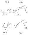
- 3 and 4 show diagrams at idle and higher speeds of a known embodiment.
- 5 and 6 show diagrams at idle and high speed of an embodiment according to the invention.
- 1 and 2 1 represents the pump piston liner, 2 the nozzle body with the nozzle needle 3, and 4 the nozzle needle spring, which is arranged in a component 5 braced with the pump piston liner.
- 6 is the backup piston and 7 is the backup piston liner.
- the end face 8 of the escape piston 6 is pressurized via a bore 9 by the pressure in the working space 10 of the pump piston 11 guided in the pump piston bushing 1.
- 12 is the storage space in the alternative piston liner 7, which is in communication with the working chamber 10 when the alternative piston 6 is lifted off.
- the piston surface 13 of the evasive piston 6 opposite the end face 8 is acted upon by the pressure in a damping chamber 14.
- the damping chamber 14 can also be filled by leakage fuel passing between the alternative piston 6 and the alternative piston bushing 7.
- the limiting plate 15 has a central bore 16, into which a cylinder pin 17 formed in one piece with the escape piston 6 is immersed.
- the cylinder pin 17 fits into the bore 16.
- This cylinder pin has a bevel 18 on one side, the depth of which determines a throttle cross section between the pin and the bore 16 of the limiting plate 15.
- the fuel emerging through the throttle opening 20 can flow through the spring chamber and an outlet 21.
- the evasive piston 6 is pressed upwards by the nozzle needle spring 4.
- the damping chamber 14 fills with fuel flowing in from the spring chamber. Much more time is available for this than for displacing the fuel from the damping chamber 14, so that the small pressure difference is usually sufficient to overcome the throttle opening 20.
- the evasive piston bushing 7 has an annular depression 22 which surrounds the evasive piston 6 and which enlarges the damping space 14.
- the limiting plate 15 and also the evasive piston 6 are interchangeable, so that the calibration of the throttle opening 20 can be changed to adapt to different engine types.
- the escape piston 6 is supported by the central pin 17 against the spring plate 24 which is turned away from the point of attack 23 on the nozzle needle 3.
- the diagrams according to FIGS. 3 and 4 represent the injection course according to the state of the art.
- the diagram according to FIG. 3 shows the injection course at idling and the diagram according to FIG. 4 shows the injection course at highest speed and full load the injection quantity and the injection time is plotted on the abscissa.
- a represents the pre-injection and b the main injection.
- the interval c ' is reduced, but has not disappeared.
- a1 represents the pilot injection
- b1 the main injection.
- the pre-injection a 1 in relation to the main injection b 1 is larger than in the diagram according to FIG. 3. Relative to the pre-injection a 1, the main injection b 1 is thus reduced when idling.
- the pilot injection a 1 passes completely into the main injection b 1, i.e. the interval c 'according to FIG. 4 has completely disappeared.
Landscapes
- Engineering & Computer Science (AREA)
- Chemical & Material Sciences (AREA)
- Combustion & Propulsion (AREA)
- Mechanical Engineering (AREA)
- General Engineering & Computer Science (AREA)
- Fuel-Injection Apparatus (AREA)
- Feeding And Controlling Fuel (AREA)
Claims (8)
- Dispositif d'injection de carburant pour des moteurs à combustion interne à injection, en particulier gicleur de pompe, comprenant une aiguille d'injection disposée dans le corps (2) du gicleur et commandée par ressort dans le sens de la fermeture, dans lequel le volume de refoulement placé devant le siège de l'aiguille d'injection communique avec le volume de travail (10) de la pompe et dans lequel est prévu un piston alternatif (6) qui est déplaçable dans un volume d'accumulation (12) disposé dans un élément séparé (7) et solidarisé avec le corps (2) du gicleur, et commandé par ressort en direction du volume de travail (10) de la pompe, ledit piston alternatif étant déplacé contre la force du ressort lors d'un dépassement d'une pression prédéterminée dans le volume de travail (10) du piston de pompe (11) et déterminant dans sa position déplacée la capacité du volume d'accumulation (12), le volume d'accumulation recevant du volume de travail (10) du piston de pompe (11) une quantité de carburant correspondant à sa capacité qui, après la fin de l'opération d'injection, est renvoyée pour l'essentiel dans le volume de travail (10) du piston de pompe (11) et le piston alternatif (6) étant de préférence appliqué contre le ressort (4) de l'aiguille d'injection, ledit piston alternatif (6) étant sollicité sur sa surface de piston opposée au volume d'accumulation (12) par la pression dans un volume (14) pouvant être rempli de carburant et communiquant avec un écoulement (21) et/ou un autre volume, caractérisé en ce que, pour la conformation en tant que volume d'amortissement, le volume (14) pouvant être rempli de carburant est relié par l'intermédiaire d'une section d'étranglement (20) à l'écoulement (21) et/ou un autre volume, et que la section d'étranglement (20) est constituée par un trou (16) d'une plaque périphérique (15) et par un tourillon (17) du piston alternatif (6) plongeant dans ledit trou.
- Dispositif d'injection de carburant selon la revendication 1, caractérisé en ce que l'élément séparé (7) pour la réception du piston alternatif (6) est solidarisé avec l'élément (5) qui reçoit l'aiguille d'injection (4), avec interposition de la plaque périphérique (15) qui délimite le volume d'amortissement (14).
- Dispositif d'injection de carburant selon l'une des revendications 1 ou 2, caractérisé en ce que l'écoulement (21) communique avec le volume d'aspiration de la pompe.
- Dispositif d'injection de carburant selon l'une des revendications 1, 2 ou 3, caractérisé en ce que le trou (16) est de forme circulaire et que le tourillon (17) présente une section circulaire et un méplat latéral (18).
- Dispositif d'injection de carburant selon l'une des revendications 1 à 4, caractérisé en ce que le volume d'amortissement (14) se situe dans la chemise (7) du piston alternatif.
- Dispositif d'injection de carburant selon l'une des revendications 1 à 5, caractérisé en ce qu'une partie du volume d'amortissement (14) est constituée par un creux annulaire qui entoure l'alésage de guidage de la chemise (7) du piston alternatif.
- Dispositif d'injection de carburant selon l'une des revendications 1 à 6, caractérisé en ce que le trou (16) est centré dans la plaque périphérique (15) de forme circulaire et que le tourillon (17) est monté de manière centrée sur le piston alternatif (6).
- Dispositif d'injection de carburant selon l'une des revendications 1 à 7, caractérisé en ce que le piston alternatif (6), au moyen du tourillon (17), prend appui sur la coupelle de ressort (24) située du côté opposée au point d'attaque du ressort (4) de l'aiguille d'injection sur ladite aiguille d'injection.
Applications Claiming Priority (2)
| Application Number | Priority Date | Filing Date | Title |
|---|---|---|---|
| AT228/87 | 1987-02-04 | ||
| AT22887 | 1987-02-04 |
Publications (3)
| Publication Number | Publication Date |
|---|---|
| EP0277939A2 EP0277939A2 (fr) | 1988-08-10 |
| EP0277939A3 EP0277939A3 (en) | 1989-12-06 |
| EP0277939B1 true EP0277939B1 (fr) | 1992-11-04 |
Family
ID=3484958
Family Applications (1)
| Application Number | Title | Priority Date | Filing Date |
|---|---|---|---|
| EP88890027A Expired - Lifetime EP0277939B1 (fr) | 1987-02-04 | 1988-02-04 | Dispositif d'injection de combustible |
Country Status (5)
| Country | Link |
|---|---|
| US (1) | US4928886A (fr) |
| EP (1) | EP0277939B1 (fr) |
| JP (1) | JP2523759B2 (fr) |
| AT (1) | ATE82042T1 (fr) |
| DE (1) | DE3875627D1 (fr) |
Cited By (7)
| Publication number | Priority date | Publication date | Assignee | Title |
|---|---|---|---|---|
| DE3900763A1 (de) * | 1989-01-12 | 1990-07-19 | Voest Alpine Automotive | Kraftstoffeinspritzduese |
| WO1990008257A1 (fr) * | 1989-01-12 | 1990-07-26 | Voest-Alpine Automotive Gesellschaft M.B.H. | Injecteur de carburant |
| DE10160080A1 (de) * | 2001-12-07 | 2003-06-26 | Siemens Ag | Pumpe-Düse-Einheit |
| WO2003067074A1 (fr) | 2002-02-07 | 2003-08-14 | Volkswagen Mechatronic Gmbh & Co. Kg | Procede et dispositif pour piloter une soupape de commande d'un ensemble pompe-gicleur |
| WO2003081007A1 (fr) | 2002-03-27 | 2003-10-02 | Siemens Aktiengesellschaft | Procede et dispositif de detection du moment d'impact du pointeau d'une soupape de commande piezoelectrique |
| DE10242376A1 (de) * | 2002-09-12 | 2004-03-25 | Siemens Ag | Pumpe-Düse-Einheit und Verfahren zur Einstellung der Härte von Anlagebereichen eines Steuerventils |
| DE10310120B4 (de) * | 2003-03-07 | 2014-02-13 | Continental Automotive Gmbh | Verfahren zur Bestimmung der auf einen Piezoaktor ausgeübten Last sowie Verfahren und Vorrichtung zur Ansteuerung eines Piezoaktors eines Steuerventils einer Pumpe-Düse-Einheit |
Families Citing this family (13)
| Publication number | Priority date | Publication date | Assignee | Title |
|---|---|---|---|---|
| GB9302344D0 (en) * | 1993-02-06 | 1993-03-24 | Lucas Ind Plc | Fuel system for engines |
| DE4340874C2 (de) * | 1993-12-01 | 1996-10-24 | Bosch Gmbh Robert | Kraftstoff-Einspritzdüse für Brennkraftmaschinen |
| US5645224A (en) * | 1995-03-27 | 1997-07-08 | Caterpillar Inc. | Modulating flow diverter for a fuel injector |
| GB9609382D0 (en) * | 1996-05-03 | 1996-07-10 | Lucas Ind Plc | Fuel injection system |
| GB9624513D0 (en) * | 1996-11-26 | 1997-01-15 | Lucas Ind Plc | Injector |
| US5743237A (en) * | 1997-01-28 | 1998-04-28 | Caterpillar Inc. | Hydraulically-actuated fuel injector with needle valve operated spill passage |
| GB9714647D0 (en) * | 1997-07-12 | 1997-09-17 | Lucas Ind Plc | Injector |
| DE19844891A1 (de) * | 1998-09-30 | 2000-04-06 | Bosch Gmbh Robert | Kraftstoffeinspritzventil für Brennkraftmaschinen |
| US6749130B2 (en) | 2000-12-08 | 2004-06-15 | Caterpillar Inc | Check line valve faster venting method |
| DE10203264A1 (de) * | 2001-02-20 | 2002-11-07 | Volkswagen Ag | Kraftstoffeinspritzdüse mit Ausweichkolben |
| DE10119602A1 (de) * | 2001-04-21 | 2002-10-24 | Bosch Gmbh Robert | Kraftstoffeinspritzeinrichtung für eine Brennkraftmaschine |
| US20050156057A1 (en) * | 2002-09-12 | 2005-07-21 | Volkswagen Mechatronic Gmbh & Co. Kg | Pump-nozzle unit and method for setting the hardness of bearing regions of a control valve |
| CN116006367B (zh) * | 2023-03-24 | 2023-07-21 | 哈尔滨工程大学 | 一种基于双电磁阀控制实现燃油高精度喷射的电控喷油器 |
Family Cites Families (15)
| Publication number | Priority date | Publication date | Assignee | Title |
|---|---|---|---|---|
| CA487403A (fr) * | 1952-10-21 | Edward Walter Nicolls Wilfrid | Ajutages d'injection de combustible liquide pour moteurs a combustion interne | |
| US2420550A (en) * | 1942-10-20 | 1947-05-13 | Miller Ralph | Liquid fuel injection apparatus |
| GB634030A (en) * | 1948-03-09 | 1950-03-15 | Cav Ltd | Improvements relating to liquid fuel injection nozzles for internal combustion engines |
| FR1515388A (fr) * | 1966-03-30 | 1968-03-01 | Bosch Gmbh Robert | Soupape d'injection de carburant pour la pré-injection et l'injection principale |
| GB1180630A (en) * | 1966-08-01 | 1970-02-04 | Peugeot | Improvements in or relating to Fuel Injection Devices for Compression Ignited Internal Combustion Engines |
| CH447714A (de) * | 1967-03-22 | 1967-11-30 | Huber Robert | Sicherheitsvorrichtung an elektromagnetischen Einspritzventilen von Verbrennungsmotoren |
| GB1406216A (en) * | 1971-10-30 | 1975-09-17 | Cav Ltd | Fuel injection nozzle units |
| JPS5523375A (en) * | 1978-08-09 | 1980-02-19 | Diesel Kiki Co Ltd | Fuel injection valve for internal combustion engine |
| DE3409924A1 (de) * | 1983-03-31 | 1984-10-11 | AVL Gesellschaft für Verbrennungskraftmaschinen und Messtechnik mbH, Prof. Dr.Dr.h.c. Hans List, Graz | Duesenhalter fuer eine kraftstoffeinspritzduese |
| US4566635A (en) * | 1983-08-10 | 1986-01-28 | Robert Bosch Gmbh | Fuel injection nozzle for internal combustion engines |
| JPS6155362A (ja) * | 1984-08-25 | 1986-03-19 | Isuzu Motors Ltd | 燃料噴射ノズル |
| DE3581160D1 (de) * | 1984-09-14 | 1991-02-07 | Bosch Gmbh Robert | Elektrisch gesteuerte kraftstoffeinspritzpumpe fuer brennkraftmaschinen. |
| DE3521428A1 (de) * | 1985-06-14 | 1986-12-18 | Robert Bosch Gmbh, 7000 Stuttgart | Kraftstoffeinspritzvorrichtung fuer brennkraftmaschinen |
| JPH0424136Y2 (fr) * | 1985-12-02 | 1992-06-05 | ||
| GB2189596B (en) * | 1986-04-16 | 1990-08-01 | Pa Consulting Services | Methods of and apparatus for preparing tissue specimens |
-
1988
- 1988-02-03 JP JP63022171A patent/JP2523759B2/ja not_active Expired - Lifetime
- 1988-02-04 EP EP88890027A patent/EP0277939B1/fr not_active Expired - Lifetime
- 1988-02-04 DE DE8888890027T patent/DE3875627D1/de not_active Expired - Fee Related
- 1988-02-04 AT AT88890027T patent/ATE82042T1/de not_active IP Right Cessation
-
1989
- 1989-10-02 US US07/415,470 patent/US4928886A/en not_active Expired - Fee Related
Cited By (8)
| Publication number | Priority date | Publication date | Assignee | Title |
|---|---|---|---|---|
| DE3900763A1 (de) * | 1989-01-12 | 1990-07-19 | Voest Alpine Automotive | Kraftstoffeinspritzduese |
| WO1990008257A1 (fr) * | 1989-01-12 | 1990-07-26 | Voest-Alpine Automotive Gesellschaft M.B.H. | Injecteur de carburant |
| US5125581A (en) * | 1989-01-12 | 1992-06-30 | Voest-Alpine Automotive Gesellschaft M.B.H. | Fuel injection nozzle |
| DE10160080A1 (de) * | 2001-12-07 | 2003-06-26 | Siemens Ag | Pumpe-Düse-Einheit |
| WO2003067074A1 (fr) | 2002-02-07 | 2003-08-14 | Volkswagen Mechatronic Gmbh & Co. Kg | Procede et dispositif pour piloter une soupape de commande d'un ensemble pompe-gicleur |
| WO2003081007A1 (fr) | 2002-03-27 | 2003-10-02 | Siemens Aktiengesellschaft | Procede et dispositif de detection du moment d'impact du pointeau d'une soupape de commande piezoelectrique |
| DE10242376A1 (de) * | 2002-09-12 | 2004-03-25 | Siemens Ag | Pumpe-Düse-Einheit und Verfahren zur Einstellung der Härte von Anlagebereichen eines Steuerventils |
| DE10310120B4 (de) * | 2003-03-07 | 2014-02-13 | Continental Automotive Gmbh | Verfahren zur Bestimmung der auf einen Piezoaktor ausgeübten Last sowie Verfahren und Vorrichtung zur Ansteuerung eines Piezoaktors eines Steuerventils einer Pumpe-Düse-Einheit |
Also Published As
| Publication number | Publication date |
|---|---|
| US4928886A (en) | 1990-05-29 |
| JP2523759B2 (ja) | 1996-08-14 |
| EP0277939A3 (en) | 1989-12-06 |
| EP0277939A2 (fr) | 1988-08-10 |
| ATE82042T1 (de) | 1992-11-15 |
| JPS63198774A (ja) | 1988-08-17 |
| DE3875627D1 (de) | 1992-12-10 |
Similar Documents
| Publication | Publication Date | Title |
|---|---|---|
| EP0277939B1 (fr) | Dispositif d'injection de combustible | |
| DE4313852B4 (de) | Kraftstoffeinspritzeinrichtung für Brennkraftmaschinen | |
| EP1117920B1 (fr) | Injecteur a rampe commune | |
| EP1342005B1 (fr) | Systeme d'injection de carburant pour moteurs a combustion interne | |
| WO1998040623A1 (fr) | Soupape pour reguler des fluides | |
| DE3423340A1 (de) | Kraftstoff-einspritzeinheit mit elektromagnetischem steuerventil | |
| EP1234112A1 (fr) | Systeme d'injection de carburant pour moteurs a combustion interne | |
| EP1387937B1 (fr) | Soupape d'injection de carburant pour moteurs a combustion, comprenant une chambre d'amortissement reduisant les oscillations de pression | |
| DE2825982A1 (de) | Kraftstoffeinspritzduese fuer brennkraftmaschinen | |
| DE10020867B4 (de) | Common-Rail-Injektor | |
| EP0688950A1 (fr) | Système d'injection de carburant | |
| DE2938412A1 (de) | Kraftstoffeinspritzduese | |
| DE19946830A1 (de) | Ventil zum Steuern von Flüssigkeiten | |
| EP1621759B1 (fr) | Injecteur pour rampe commune | |
| EP2836696B1 (fr) | Injecteur d'un système d'injection de carburant modulaire à rampe commune, doté d'un limiteur de débit | |
| EP1518050B1 (fr) | Injecteur pour un systeme d'injection | |
| EP0135872A2 (fr) | Injecteur de combustible pour moteurs à combustion interne | |
| DE10307873A1 (de) | Sackloch- und Sitzloch-Einspritzdüse für eine Brennkraftmaschine mit einem Übergangskegel zwischen Sackloch und Düsennadelsitz | |
| DE3325451A1 (de) | Kraftstoffeinlassventil fuer brennkraftmaschinen | |
| EP1384000B1 (fr) | Dispositif d'injection de carburant pour moteur a combustion | |
| EP1377745B1 (fr) | Procede pour actionner une unite pompe-ajutage et unite pompe-ajutage correspondante | |
| DE3006390A1 (de) | Kraftstoffeinspritzduese | |
| DE2641203C2 (de) | Kraftstoffeinspritzpumpe für eine Brennkraftmaschine | |
| DE2726300A1 (de) | Kraftstoffeinspritzduese | |
| DE3343157A1 (de) | Treibstoffeinspritzeinrichtung |
Legal Events
| Date | Code | Title | Description |
|---|---|---|---|
| PUAI | Public reference made under article 153(3) epc to a published international application that has entered the european phase |
Free format text: ORIGINAL CODE: 0009012 |
|
| AK | Designated contracting states |
Kind code of ref document: A2 Designated state(s): AT CH DE FR GB IT LI SE |
|
| PUAL | Search report despatched |
Free format text: ORIGINAL CODE: 0009013 |
|
| AK | Designated contracting states |
Kind code of ref document: A3 Designated state(s): AT CH DE FR GB IT LI SE |
|
| 17P | Request for examination filed |
Effective date: 19900104 |
|
| 17Q | First examination report despatched |
Effective date: 19910212 |
|
| GRAA | (expected) grant |
Free format text: ORIGINAL CODE: 0009210 |
|
| AK | Designated contracting states |
Kind code of ref document: B1 Designated state(s): AT CH DE FR GB IT LI SE |
|
| PG25 | Lapsed in a contracting state [announced via postgrant information from national office to epo] |
Ref country code: SE Effective date: 19921104 |
|
| REF | Corresponds to: |
Ref document number: 82042 Country of ref document: AT Date of ref document: 19921115 Kind code of ref document: T |
|
| REF | Corresponds to: |
Ref document number: 3875627 Country of ref document: DE Date of ref document: 19921210 |
|
| RAP2 | Party data changed (patent owner data changed or rights of a patent transferred) |
Owner name: ROBERT BOSCH AKTIENGESELLSCHAFT |
|
| REG | Reference to a national code |
Ref country code: CH Ref legal event code: PUE Owner name: ROBERT BOSCH AKTIENGESELLSCHAFT |
|
| ITF | It: translation for a ep patent filed |
Owner name: DR. ING. A. RACHELI & C. |
|
| PG25 | Lapsed in a contracting state [announced via postgrant information from national office to epo] |
Ref country code: AT Effective date: 19930204 |
|
| PG25 | Lapsed in a contracting state [announced via postgrant information from national office to epo] |
Ref country code: LI Effective date: 19930228 Ref country code: CH Effective date: 19930228 |
|
| GBT | Gb: translation of ep patent filed (gb section 77(6)(a)/1977) |
Effective date: 19930203 |
|
| ET | Fr: translation filed | ||
| PLBE | No opposition filed within time limit |
Free format text: ORIGINAL CODE: 0009261 |
|
| STAA | Information on the status of an ep patent application or granted ep patent |
Free format text: STATUS: NO OPPOSITION FILED WITHIN TIME LIMIT |
|
| 26N | No opposition filed | ||
| REG | Reference to a national code |
Ref country code: CH Ref legal event code: PL |
|
| PGFP | Annual fee paid to national office [announced via postgrant information from national office to epo] |
Ref country code: FR Payment date: 19970114 Year of fee payment: 10 |
|
| PGFP | Annual fee paid to national office [announced via postgrant information from national office to epo] |
Ref country code: DE Payment date: 19970124 Year of fee payment: 10 |
|
| PGFP | Annual fee paid to national office [announced via postgrant information from national office to epo] |
Ref country code: GB Payment date: 19980112 Year of fee payment: 11 |
|
| PG25 | Lapsed in a contracting state [announced via postgrant information from national office to epo] |
Ref country code: FR Free format text: THE PATENT HAS BEEN ANNULLED BY A DECISION OF A NATIONAL AUTHORITY Effective date: 19980228 |
|
| PG25 | Lapsed in a contracting state [announced via postgrant information from national office to epo] |
Ref country code: DE Free format text: LAPSE BECAUSE OF NON-PAYMENT OF DUE FEES Effective date: 19981103 |
|
| REG | Reference to a national code |
Ref country code: FR Ref legal event code: ST |
|
| PG25 | Lapsed in a contracting state [announced via postgrant information from national office to epo] |
Ref country code: GB Free format text: LAPSE BECAUSE OF NON-PAYMENT OF DUE FEES Effective date: 19990204 |
|
| GBPC | Gb: european patent ceased through non-payment of renewal fee |
Effective date: 19990204 |
|
| PG25 | Lapsed in a contracting state [announced via postgrant information from national office to epo] |
Ref country code: IT Free format text: LAPSE BECAUSE OF NON-PAYMENT OF DUE FEES;WARNING: LAPSES OF ITALIAN PATENTS WITH EFFECTIVE DATE BEFORE 2007 MAY HAVE OCCURRED AT ANY TIME BEFORE 2007. THE CORRECT EFFECTIVE DATE MAY BE DIFFERENT FROM THE ONE RECORDED. Effective date: 20050204 |