EP0268200A2 - Couvercle de soupape pour la culasse d'un moteur à combustion interne - Google Patents
Couvercle de soupape pour la culasse d'un moteur à combustion interne Download PDFInfo
- Publication number
- EP0268200A2 EP0268200A2 EP87116652A EP87116652A EP0268200A2 EP 0268200 A2 EP0268200 A2 EP 0268200A2 EP 87116652 A EP87116652 A EP 87116652A EP 87116652 A EP87116652 A EP 87116652A EP 0268200 A2 EP0268200 A2 EP 0268200A2
- Authority
- EP
- European Patent Office
- Prior art keywords
- valve cover
- seal
- cylinder head
- rubber
- marginal portion
- Prior art date
- Legal status (The legal status is an assumption and is not a legal conclusion. Google has not performed a legal analysis and makes no representation as to the accuracy of the status listed.)
- Granted
Links
- 238000002485 combustion reaction Methods 0.000 title claims abstract description 5
- 238000007789 sealing Methods 0.000 claims abstract description 13
- 238000001816 cooling Methods 0.000 claims abstract description 4
- 229920001971 elastomer Polymers 0.000 claims description 28
- 239000003566 sealing material Substances 0.000 claims description 7
- 239000002318 adhesion promoter Substances 0.000 claims description 5
- 229910052751 metal Inorganic materials 0.000 claims description 4
- 239000002184 metal Substances 0.000 claims description 4
- 238000002347 injection Methods 0.000 claims description 2
- 239000007924 injection Substances 0.000 claims description 2
- 239000007822 coupling agent Substances 0.000 abstract description 4
- 229920002379 silicone rubber Polymers 0.000 abstract description 3
- 239000000463 material Substances 0.000 abstract description 2
- 238000013016 damping Methods 0.000 abstract 1
- 238000004073 vulcanization Methods 0.000 abstract 1
- 230000000694 effects Effects 0.000 description 4
- 230000005540 biological transmission Effects 0.000 description 3
- 230000015572 biosynthetic process Effects 0.000 description 3
- 150000001875 compounds Chemical class 0.000 description 2
- 238000010438 heat treatment Methods 0.000 description 2
- 238000000465 moulding Methods 0.000 description 2
- 239000004945 silicone rubber Substances 0.000 description 2
- 229920000459 Nitrile rubber Polymers 0.000 description 1
- CTQNGGLPUBDAKN-UHFFFAOYSA-N O-Xylene Chemical compound CC1=CC=CC=C1C CTQNGGLPUBDAKN-UHFFFAOYSA-N 0.000 description 1
- BLRPTPMANUNPDV-UHFFFAOYSA-N Silane Chemical compound [SiH4] BLRPTPMANUNPDV-UHFFFAOYSA-N 0.000 description 1
- 239000000853 adhesive Substances 0.000 description 1
- 229910052782 aluminium Inorganic materials 0.000 description 1
- XAGFODPZIPBFFR-UHFFFAOYSA-N aluminium Chemical compound [Al] XAGFODPZIPBFFR-UHFFFAOYSA-N 0.000 description 1
- 238000004132 cross linking Methods 0.000 description 1
- 230000001627 detrimental effect Effects 0.000 description 1
- 238000011161 development Methods 0.000 description 1
- 230000018109 developmental process Effects 0.000 description 1
- 238000000034 method Methods 0.000 description 1
- 229920000058 polyacrylate Polymers 0.000 description 1
- 229910000077 silane Inorganic materials 0.000 description 1
- 230000003746 surface roughness Effects 0.000 description 1
- 238000004381 surface treatment Methods 0.000 description 1
- 239000008096 xylene Substances 0.000 description 1
Images
Classifications
-
- F—MECHANICAL ENGINEERING; LIGHTING; HEATING; WEAPONS; BLASTING
- F02—COMBUSTION ENGINES; HOT-GAS OR COMBUSTION-PRODUCT ENGINE PLANTS
- F02F—CYLINDERS, PISTONS OR CASINGS, FOR COMBUSTION ENGINES; ARRANGEMENTS OF SEALINGS IN COMBUSTION ENGINES
- F02F7/00—Casings, e.g. crankcases or frames
- F02F7/006—Camshaft or pushrod housings
-
- B—PERFORMING OPERATIONS; TRANSPORTING
- B29—WORKING OF PLASTICS; WORKING OF SUBSTANCES IN A PLASTIC STATE IN GENERAL
- B29C—SHAPING OR JOINING OF PLASTICS; SHAPING OF MATERIAL IN A PLASTIC STATE, NOT OTHERWISE PROVIDED FOR; AFTER-TREATMENT OF THE SHAPED PRODUCTS, e.g. REPAIRING
- B29C70/00—Shaping composites, i.e. plastics material comprising reinforcements, fillers or preformed parts, e.g. inserts
- B29C70/68—Shaping composites, i.e. plastics material comprising reinforcements, fillers or preformed parts, e.g. inserts by incorporating or moulding on preformed parts, e.g. inserts or layers, e.g. foam blocks
- B29C70/74—Moulding material on a relatively small portion of the preformed part, e.g. outsert moulding
- B29C70/76—Moulding on edges or extremities of the preformed part
-
- F—MECHANICAL ENGINEERING; LIGHTING; HEATING; WEAPONS; BLASTING
- F02—COMBUSTION ENGINES; HOT-GAS OR COMBUSTION-PRODUCT ENGINE PLANTS
- F02B—INTERNAL-COMBUSTION PISTON ENGINES; COMBUSTION ENGINES IN GENERAL
- F02B77/00—Component parts, details or accessories, not otherwise provided for
-
- B—PERFORMING OPERATIONS; TRANSPORTING
- B29—WORKING OF PLASTICS; WORKING OF SUBSTANCES IN A PLASTIC STATE IN GENERAL
- B29C—SHAPING OR JOINING OF PLASTICS; SHAPING OF MATERIAL IN A PLASTIC STATE, NOT OTHERWISE PROVIDED FOR; AFTER-TREATMENT OF THE SHAPED PRODUCTS, e.g. REPAIRING
- B29C45/00—Injection moulding, i.e. forcing the required volume of moulding material through a nozzle into a closed mould; Apparatus therefor
- B29C45/14—Injection moulding, i.e. forcing the required volume of moulding material through a nozzle into a closed mould; Apparatus therefor incorporating preformed parts or layers, e.g. injection moulding around inserts or for coating articles
- B29C45/14336—Coating a portion of the article, e.g. the edge of the article
- B29C2045/14459—Coating a portion of the article, e.g. the edge of the article injecting seal elements
-
- B—PERFORMING OPERATIONS; TRANSPORTING
- B29—WORKING OF PLASTICS; WORKING OF SUBSTANCES IN A PLASTIC STATE IN GENERAL
- B29C—SHAPING OR JOINING OF PLASTICS; SHAPING OF MATERIAL IN A PLASTIC STATE, NOT OTHERWISE PROVIDED FOR; AFTER-TREATMENT OF THE SHAPED PRODUCTS, e.g. REPAIRING
- B29C45/00—Injection moulding, i.e. forcing the required volume of moulding material through a nozzle into a closed mould; Apparatus therefor
- B29C45/14—Injection moulding, i.e. forcing the required volume of moulding material through a nozzle into a closed mould; Apparatus therefor incorporating preformed parts or layers, e.g. injection moulding around inserts or for coating articles
- B29C45/14336—Coating a portion of the article, e.g. the edge of the article
-
- B—PERFORMING OPERATIONS; TRANSPORTING
- B29—WORKING OF PLASTICS; WORKING OF SUBSTANCES IN A PLASTIC STATE IN GENERAL
- B29L—INDEXING SCHEME ASSOCIATED WITH SUBCLASS B29C, RELATING TO PARTICULAR ARTICLES
- B29L2031/00—Other particular articles
- B29L2031/26—Sealing devices, e.g. packaging for pistons or pipe joints
-
- F—MECHANICAL ENGINEERING; LIGHTING; HEATING; WEAPONS; BLASTING
- F02—COMBUSTION ENGINES; HOT-GAS OR COMBUSTION-PRODUCT ENGINE PLANTS
- F02F—CYLINDERS, PISTONS OR CASINGS, FOR COMBUSTION ENGINES; ARRANGEMENTS OF SEALINGS IN COMBUSTION ENGINES
- F02F1/00—Cylinders; Cylinder heads
- F02F1/02—Cylinders; Cylinder heads having cooling means
- F02F1/10—Cylinders; Cylinder heads having cooling means for liquid cooling
- F02F2001/104—Cylinders; Cylinder heads having cooling means for liquid cooling using an open deck, i.e. the water jacket is open at the block top face
-
- Y—GENERAL TAGGING OF NEW TECHNOLOGICAL DEVELOPMENTS; GENERAL TAGGING OF CROSS-SECTIONAL TECHNOLOGIES SPANNING OVER SEVERAL SECTIONS OF THE IPC; TECHNICAL SUBJECTS COVERED BY FORMER USPC CROSS-REFERENCE ART COLLECTIONS [XRACs] AND DIGESTS
- Y10—TECHNICAL SUBJECTS COVERED BY FORMER USPC
- Y10S—TECHNICAL SUBJECTS COVERED BY FORMER USPC CROSS-REFERENCE ART COLLECTIONS [XRACs] AND DIGESTS
- Y10S277/00—Seal for a joint or juncture
- Y10S277/922—Bonding or joining for manufacture of seal
-
- Y—GENERAL TAGGING OF NEW TECHNOLOGICAL DEVELOPMENTS; GENERAL TAGGING OF CROSS-SECTIONAL TECHNOLOGIES SPANNING OVER SEVERAL SECTIONS OF THE IPC; TECHNICAL SUBJECTS COVERED BY FORMER USPC CROSS-REFERENCE ART COLLECTIONS [XRACs] AND DIGESTS
- Y10—TECHNICAL SUBJECTS COVERED BY FORMER USPC
- Y10S—TECHNICAL SUBJECTS COVERED BY FORMER USPC CROSS-REFERENCE ART COLLECTIONS [XRACs] AND DIGESTS
- Y10S277/00—Seal for a joint or juncture
- Y10S277/924—Deformation, material removal, or molding for manufacture of seal
Definitions
- the invention relates to a valve cover for the cylinder head of an internal combustion engine, with a rubber seal attached to the edge surface of the valve cover facing the cylinder head and with holes for the passage of threaded bolts for connecting the valve cover to the cylinder head.
- the seal is clamped in a groove in the edge surface, so that it does not fall out of the groove when handling the valve cover, for example when the valve cover is placed on the cylinder head.
- the seal is inserted into the groove manually and is labor and time consuming.
- the groove cross section has an oversize, so that there is practically no sealing effect and hardly any clamping effect between the contacting surfaces of the groove and seal. The latter is rather achieved by side ribs or knobs on the seal, which are even more detrimental to a sealing effect.
- the seal is therefore allowed to overlap the edge of the groove and to rest on the flat edge surface areas which are adjacent to the groove and which are easy to machine. Since the seal is not chambered in these edge surface areas, the sealing material is due to the tightening of the valve cover on the cylinder head caused transverse expansion and the heating during operation permanently deformed, so that the seal is not reusable. In addition, the transverse expansion in the usual implementation of the threaded bolts through holes in an edge flange of the valve cover and the holes in the seal causes the seal to tear through the threaded bolts. This also affects reusability.
- Valve covers without a groove in the edge surface and with lead-through holes for threaded bolts in an edge flange result in the same difficulties with regard to transverse expansion and the risk of the seal tearing. In addition, the fixing and centering of the seal on the edge surface is difficult during assembly.
- the invention has for its object to provide a valve cover of the generic type, the assembly is easier with high tightness between the valve cover and the cylinder head.
- this object is achieved in that the sealing material is molded onto the edge surface of the valve cover with the formation of the seal and the interposition of at least one adhesion promoter in the thermally softened state, so that the seal is fastened to the edge surface in the desired shape after cooling.
- edge surface has a circumferential groove for receiving a part of the sealing material. This leads to an increase in the effective adhesion area, since the sealing material lies tightly against the wall when it is injected into the groove.
- the valve cover edge receiving the seal is preferably provided with a flange projecting outwards.
- the edge surface of the valve cover facing the cylinder head but also the shoulder surface of the flange facing away from the cylinder head can serve as an abutment for a sealing mold part encompassing the flange, in order to hold this sealing mold part on the valve cover while molding the seal and at the same time by Groove in the edge surface of the valve cover and the second seal mold part to close the cavity tightly when injecting the sealing material.
- the through holes can be formed in the bottom of the hood-shaped valve cover. This prevents the seal from being penetrated by threaded bolts, so that its shape is simpler.
- the threaded bolts can be stud bolts with threaded sections at both ends, the length of the unthreaded central section of the stud bolts being selected in accordance with the desired prestressing of the seal and rubber sleeves.
- One threaded section of the stud bolts can be firmly screwed into the cylinder head before installing the valve cover, so that only the valve cover has to be placed on the cylinder head and nuts on the other threaded sections of the stud bolts (possibly with the interposition of washers). Both can be carried out quickly and easily by means of an assembly robot, the central sections of the stud bolts representing a path limitation for the nuts.
- valve cover can be provided with stiffening ribs, which not only ensure stiffening of the valve cover, but also ensure a uniform transmission of the clamping force to the seal when the nuts are tightened when the through holes are formed in the valve cover base, so that the seal is evenly pretensioned and even Sealing effect is provided over the entire circumference of the lid.
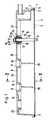
- the valve cover shown is made of aluminum. It serves to cover the cylinder head having the valves on the cylinder block of an internal combustion engine and has the shape of a hood.
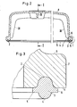
- the valve cover is provided with a circumferential groove 2 which is approximately semicircular in cross section.
- the groove contains a seal 3 made of temperature and oil-resistant rubber, which can be silicone rubber, nitrile rubber or polyacrylate rubber.
- the rubber is injected into the groove 2 with the interposition of an adhesion promoter (not shown) in a thermally softened state, so that after cooling it protrudes from the groove 2, forming a sealing lip 4, and with side flanges 5 on the edge surface 1 is present.
- the adhesive agent in a silicone rubber seal is preferably silane.
- the coupling agent is dissolved in xylene and introduced as a thin layer in the groove 2 and on the edge surface next to the groove 2 of the preheated valve cover.
- the sealing rubber compound heated to approximately 110 °, is injected, crosslinking with the coupling agent after further heating to 250 ° C.
- a mold part with cutting edges is placed on the one hand on the edge surface 1 along the groove 2 and on the other hand on the top 6 of an outwardly projecting edge flange 7 of the valve cover, the mold part engaging around this edge flange 7.
- the rubber compound is then injected into the cavity formed by the mold part and the groove 2.
- the seal 3 is formed at the same time and any surface roughness of the groove 2 is compensated, so that a surface treatment of the edge surface 1 and the groove 2 to achieve the highest possible smoothness and thus a correspondingly high tightness not applicable.
- two layers of adhesion promoters can be used, one connecting to the metal and the other connecting to the rubber.
- the valve cover also has three holes 9 in its base 8 for the passage of threaded bolts designed as stud bolts, of which only one threaded bolt 10 is shown.
- This threaded bolt 10 has threaded sections 11 and 12 at its ends and a central unthreaded section 13.
- a sleeve 14 made of rubber is knotted into the holes 9, the Shore hardness of which is greater than that of the seal 3. Only one of the rubber sleeves 14 is shown. They each hold one of the stud bolts 10, as shown in FIG. 1.
- the rubber sleeves 14 cause a seal the stud 10 against the recessed and formed with a radially inwardly projecting flange 15 through holes 9, each flange 15 engages in an annular groove 16 on the outside of the rubber sleeve 14 inserted into the hole 9 in question.
- two metal washers 17 and 18 are embedded so that they each have an exposed abutment surface 19 and 20.
- the rubber sleeve 14 rests on the flange 15, while on the abutment surface 20 of the ring washer 18, a nut 21, which is screwed onto the upper threaded section 12, is supported via a washer 22.
- the stud bolts 10 are screwed with their lower threaded sections 11 into corresponding threaded bores of the cylinder head.
- the valve cover provided with the rubber sleeves is then placed through the rubber sleeves 14 on the cylinder head by carrying out the stud bolts 10.
- the washers 22 are then placed on the threaded sections 12 and the nuts 21 are screwed on.
- the length of the thread-free section 13 of the stud bolts 10 is in each case dimensioned such that there is a path limitation of the nuts 21 and, at the same time, the required pretension is formed in the rubber sleeves 14 and the seal 3 in order to ensure an adequate seal.
- the rubber sleeves 14 not only ensure a seal, but at the same time dampen the transmission of structure-borne noise from the cylinder head via the stud bolts 10 into the valve cover, since they prevent direct (metallic) contact between the stud bolts 10 and the valve cover.
- the rubber sleeves therefore have the same function as rubber springs and vibration dampers.
Landscapes
- Engineering & Computer Science (AREA)
- Chemical & Material Sciences (AREA)
- Mechanical Engineering (AREA)
- Combustion & Propulsion (AREA)
- General Engineering & Computer Science (AREA)
- Composite Materials (AREA)
- Cylinder Crankcases Of Internal Combustion Engines (AREA)
- Gasket Seals (AREA)
- Pressure Vessels And Lids Thereof (AREA)
Priority Applications (1)
| Application Number | Priority Date | Filing Date | Title |
|---|---|---|---|
| AT87116652T ATE72020T1 (de) | 1986-11-15 | 1987-11-11 | Ventildeckel fuer den zylinderkopf eines verbrennungsmotors. |
Applications Claiming Priority (2)
| Application Number | Priority Date | Filing Date | Title |
|---|---|---|---|
| DE19863639218 DE3639218A1 (de) | 1986-11-15 | 1986-11-15 | Ventildeckel fuer den zylinderkopf eines verbrennungsmotors |
| DE3639218 | 1986-11-15 |
Publications (3)
| Publication Number | Publication Date |
|---|---|
| EP0268200A2 true EP0268200A2 (fr) | 1988-05-25 |
| EP0268200A3 EP0268200A3 (en) | 1989-03-29 |
| EP0268200B1 EP0268200B1 (fr) | 1992-01-22 |
Family
ID=6314124
Family Applications (1)
| Application Number | Title | Priority Date | Filing Date |
|---|---|---|---|
| EP87116652A Expired - Lifetime EP0268200B1 (fr) | 1986-11-15 | 1987-11-11 | Couvercle de soupape pour la culasse d'un moteur à combustion interne |
Country Status (8)
| Country | Link |
|---|---|
| US (1) | US4819953A (fr) |
| EP (1) | EP0268200B1 (fr) |
| JP (1) | JPH01147146A (fr) |
| AT (1) | ATE72020T1 (fr) |
| CA (1) | CA1313092C (fr) |
| DE (4) | DE3639218A1 (fr) |
| ES (1) | ES2029681T3 (fr) |
| GR (1) | GR3004031T3 (fr) |
Cited By (8)
| Publication number | Priority date | Publication date | Assignee | Title |
|---|---|---|---|---|
| FR2620077A1 (fr) * | 1987-09-04 | 1989-03-10 | Ages Spa | Procede de fabrication de couvercles de protection d'organes pour moteurs de vehicules automobiles, par injections successives de polymere et d'elastomere et couvercle obtenu par ce procede |
| EP0463267A1 (fr) * | 1990-06-27 | 1992-01-02 | Regie Nationale Des Usines Renault | Dispositif d'admission pour moteur à combustion interne |
| US5228420A (en) * | 1992-09-25 | 1993-07-20 | Tsuchiya Mfg. Co., Ltd. | Valve rocker cover |
| EP0664388A1 (fr) * | 1994-01-21 | 1995-07-26 | CR Elastomere GmbH | Couvre-culbuteurs |
| EP0773358A1 (fr) * | 1995-11-10 | 1997-05-14 | Druckgusswerk Mössner GmbH | Procédé pour la production d'un dispositif d'étanchéité d'un couvre-culasse |
| WO1997017535A1 (fr) * | 1995-11-10 | 1997-05-15 | Druckgusswerk Mössner GmbH | Procede de production d'une garniture d'etancheite et dispositif de compression |
| EP0846853A1 (fr) * | 1996-12-03 | 1998-06-10 | Diehl Remscheid GmbH & Co. | Dispositif d'étanchéité d'un bâtiment |
| CN110985229A (zh) * | 2018-10-02 | 2020-04-10 | 本田技研工业株式会社 | 发动机的盖罩结构 |
Families Citing this family (45)
| Publication number | Priority date | Publication date | Assignee | Title |
|---|---|---|---|---|
| US4934715A (en) * | 1989-01-09 | 1990-06-19 | Johnson Roy E | Gasket for use with manhole covers |
| DE4221760C2 (de) * | 1991-12-17 | 1996-07-11 | Cr Elastomere Gmbh | Körperschallisolierter Deckel, insbesondere für Brennkraftmaschinen |
| ATE128207T1 (de) * | 1991-12-17 | 1995-10-15 | Cr Elastomere Gmbh | Deckel für brennkraftmaschinen. |
| US5275420A (en) * | 1992-12-16 | 1994-01-04 | Chrysler Corporation | End seals for V-type internal combustion engines and engine sealing method |
| DE4323073A1 (de) * | 1993-07-10 | 1995-01-12 | Audi Ag | Hubkolben-Brennkraftmaschine |
| ATE184680T1 (de) * | 1994-01-25 | 1999-10-15 | Alusuisse Bayrisches Druckguss | Verfahren zur herstellung eines deckels aus leichtmetallguss sowie deckel aus leichtmetallguss |
| DE19619146C2 (de) * | 1996-05-11 | 2000-01-20 | Gloeckler Dichtsysteme Guenter | Verfahren zum Aufbringen einer festhaftenden Dichtung auf eine Maschinenabdeckung |
| US5687975A (en) * | 1996-08-21 | 1997-11-18 | Fel-Pro Incorporated | Sealing assembly employing oppositely directed wedges and complementary recesses |
| DE29617276U1 (de) * | 1996-10-07 | 1998-02-05 | Sachsenring Automobiltechnik GmbH, 08058 Zwickau | Kugelgelenk |
| DE19727915A1 (de) * | 1997-07-01 | 1999-01-07 | Bayerische Motoren Werke Ag | Dichtungsanordnung zwischen geodätisch übereinander angeordneten Bauteilen, insbesondere Gehäuseteilen von Brennkraftmaschinen |
| US6045140A (en) * | 1997-07-11 | 2000-04-04 | Cummins Engine Company, Inc. | Retention gasket with cooperating cover |
| DE19744310B4 (de) * | 1997-10-07 | 2006-07-27 | Valeo Klimasysteme Gmbh | Dichtung für eine Klima- und/oder Heizungsanlage eines Fahrzeugs |
| DE29720094U1 (de) * | 1997-11-12 | 1999-03-18 | ITW Automotive Products GmbH & Co. KG, 58642 Iserlohn | Befestigungsvorrichtung |
| US6505839B1 (en) * | 1998-10-30 | 2003-01-14 | Bridgestone Corporation | Gasketed cover, cover for electronic equipment and process for producing the covers |
| DE10008864C2 (de) * | 2000-02-25 | 2003-01-16 | Dorma Gmbh & Co Kg | Beschlag mit einer Dichtung |
| JP4344460B2 (ja) * | 2000-07-11 | 2009-10-14 | 本田技研工業株式会社 | エンジン本体のシール構造 |
| DE10057379B4 (de) * | 2000-11-18 | 2005-06-30 | Mahle Filtersysteme Gmbh | Verfahren zur Herstellung eines Dichtungsflansches mit einer in diesem integrierten Dichtung |
| US6689219B2 (en) * | 2001-03-15 | 2004-02-10 | Michael Antoine Birmingham | Apparatus and method for dispensing viscous liquid material |
| JP4292321B2 (ja) * | 2001-12-07 | 2009-07-08 | 内山工業株式会社 | ガスケット |
| DE10217522B4 (de) * | 2002-04-19 | 2004-02-19 | Federal-Mogul Sealing Systems Bretten Gmbh & Co. Kg | Verfahren zur Herstellung eines Gehäusedeckels |
| US6722660B2 (en) | 2002-06-27 | 2004-04-20 | Federal-Mogul World Wide, Inc. | Molded gasket |
| DE10305900C5 (de) * | 2003-02-13 | 2014-04-17 | Jungheinrich Aktiengesellschaft | Stapler |
| DE10306211A1 (de) | 2003-02-13 | 2004-08-26 | Mann + Hummel Gmbh | Dichtung zur Abdichtung einer Verbindung zweier Formteile |
| DE10321584B4 (de) | 2003-05-14 | 2005-09-29 | Federal-Mogul Sealing Systems Bretten Gmbh | Verfahren zur Erzeugung einer Dichtung an einem Bauteil |
| US7048279B2 (en) | 2003-05-20 | 2006-05-23 | Federal-Mogul World Wide, Inc. | Laminated carrier gasket with off-set elastomeric sealing |
| JP2005050728A (ja) * | 2003-07-30 | 2005-02-24 | Nichias Corp | 燃料電池のセパレータ用ゴムガスケット |
| DE102004034235B4 (de) * | 2004-07-15 | 2006-09-21 | Federal-Mogul Sealing Systems Bretten Gmbh | Bauteil mit integrierter Dichtung |
| US7213814B2 (en) | 2004-07-28 | 2007-05-08 | Federal-Mogul Worldwide, Inc. | Seal assembly |
| DE202005010448U1 (de) | 2005-06-30 | 2006-11-09 | Mann + Hummel Gmbh | Dichtung |
| TW200711557A (en) * | 2005-09-02 | 2007-03-16 | Sunonwealth Electr Mach Ind Co | Heat dissipation device |
| US7850055B2 (en) * | 2007-03-15 | 2010-12-14 | Black & Decker Inc. | Assembly having gasket resistant to side loading by pressurized fluid |
| DE102007026513A1 (de) | 2007-06-08 | 2008-12-11 | Gustav Magenwirth Gmbh & Co. Kg | Bauteil mit zumindest einer angeformten Dichtung und Verfahren zu seiner Herstellung |
| DE102007026514A1 (de) | 2007-06-08 | 2008-12-18 | Gustav Magenwirth Gmbh & Co. Kg | Statisches Bauteil mit zumindest einer angeformten statischen Dichtung und Verfahren zu seiner Herstellung |
| DE102007063254A1 (de) | 2007-12-31 | 2009-07-02 | Mahle International Gmbh | Zylinderkopfhaube |
| CN102224364B (zh) * | 2008-11-25 | 2014-05-07 | Nok株式会社 | 双材质复合衬垫 |
| US8220430B2 (en) * | 2009-05-22 | 2012-07-17 | Ford Global Technologies | Intake system for internal combustion engine |
| US8122864B2 (en) * | 2009-05-22 | 2012-02-28 | Ford Global Technologies | Intake manifold for multicylinder internal combustion engine |
| US8100108B2 (en) * | 2009-05-22 | 2012-01-24 | Ford Global Technologies | Hydraulically operated charge air system for internal combustion engine |
| US8056534B2 (en) * | 2009-05-22 | 2011-11-15 | Ford Global Technologies | Intake manifold system for internal combustion engine |
| CN102140976A (zh) * | 2011-03-15 | 2011-08-03 | 奇瑞汽车股份有限公司 | 一种汽车发动机气门室罩盖 |
| JP5835836B2 (ja) * | 2011-05-26 | 2015-12-24 | 内山工業株式会社 | 密封構造 |
| US9845809B2 (en) | 2012-07-06 | 2017-12-19 | Trane International Inc. | Sealing joint for a compressor casing |
| JP6383203B2 (ja) * | 2014-07-25 | 2018-08-29 | Nok株式会社 | プレート一体ガスケットの製造方法 |
| US11050229B2 (en) * | 2018-07-16 | 2021-06-29 | Allied Moulded Products, Inc. | Vapor seal with angled flange |
| US11686271B1 (en) * | 2021-09-09 | 2023-06-27 | Master Packing and Rubber Company | Locomotive diesel engine cylinder head cover assembly seal |
Citations (3)
| Publication number | Priority date | Publication date | Assignee | Title |
|---|---|---|---|---|
| FR1035878A (fr) | 1951-04-18 | 1953-09-01 | Couvre-culasse pour moteurs à culbuteurs | |
| AT281502B (de) | 1967-02-14 | 1970-05-25 | H C Hans Dipl Ing Dr List | Brennkraftmaschine mit schallisolierender Verkleidung |
| GB1263077A (en) | 1968-04-26 | 1972-02-09 | John Vickers And Sons Ltd | Improvements in machinery covers |
Family Cites Families (28)
| Publication number | Priority date | Publication date | Assignee | Title |
|---|---|---|---|---|
| US3166992A (en) * | 1962-11-02 | 1965-01-26 | Gen Motors Corp | Engine block |
| US3575429A (en) * | 1968-04-10 | 1971-04-20 | Thomas & Betts Corp | Electrical connector sealing ring |
| US3623628A (en) * | 1970-02-04 | 1971-11-30 | Microdot Inc | Oil filler plug |
| DE2530181A1 (de) * | 1975-07-05 | 1977-01-27 | Reinz Dichtung Gmbh | Dichtungsring sowie verfahren zu seiner herstellung |
| DE2604126A1 (de) * | 1976-02-04 | 1977-08-11 | Schuch Lichttech Kg Adolf | Gummielastische dichtung fuer ein gehaeuse |
| CH615981A5 (en) * | 1976-07-08 | 1980-02-29 | Saurer Ag Adolph | Internal combustion engine with oil sump connected to the crank case so as to isolate structure-borne noise |
| FR2373510A1 (fr) * | 1976-12-10 | 1978-07-07 | Poudres & Explosifs Ste Nale | Procede de synthese de chloroformiates a terminaisons acryliques ou methacryliques |
| JPS5936680Y2 (ja) * | 1977-08-04 | 1984-10-09 | トヨタ自動車株式会社 | 内燃機関のシリンダヘツドカバ−取り付け装置 |
| JPS5824047Y2 (ja) * | 1978-01-30 | 1983-05-23 | トヨタ自動車株式会社 | シ−ル構造 |
| US4284479A (en) * | 1978-12-01 | 1981-08-18 | Didier Engineering Gmbh | Sealing arrangement for the oven chamber door on a coking oven |
| AT378825B (de) * | 1979-05-16 | 1985-10-10 | List Hans | Geraeuschgedaemmte hubkolben-brennkraftmaschine |
| US4345552A (en) * | 1979-12-18 | 1982-08-24 | Cummins Engine Company, Inc. | Rocker housing and rocker cover |
| JPS5938999B2 (ja) * | 1980-03-14 | 1984-09-20 | ニチアス株式会社 | ジヨイントシ−ト |
| JPS5773330U (fr) * | 1980-10-23 | 1982-05-06 | ||
| DE3113912A1 (de) * | 1981-04-07 | 1982-10-28 | Günter 7518 Bretten Hemmrich | Vorrichtung zur dichten verbindung zweier hohlkoerper |
| DE3115671A1 (de) * | 1981-04-18 | 1982-11-11 | Volkswagenwerk Ag, 3180 Wolfsburg | Gehaeuse fuer eine wassergekuehlte brennkraftmaschine |
| US4428338A (en) * | 1981-05-13 | 1984-01-31 | Hans List | Internal combustion engine |
| JPS5851249A (ja) * | 1981-09-19 | 1983-03-25 | Honda Motor Co Ltd | 内燃機関 |
| IT1196661B (it) * | 1982-05-17 | 1988-11-25 | Fiat Auto Spa | Procedimento per il montaggio di un coperchio sulla testa cilindri di un motore a combustione interna |
| US4456268A (en) * | 1982-09-30 | 1984-06-26 | Allis-Chalmers Corp. | Fastening means in sealed gasket assembly including shoulder bolt |
| DE3241205A1 (de) * | 1982-11-08 | 1984-05-10 | Westfälische Metall Industrie KG Hueck & Co, 4780 Lippstadt | Zylinderkopfhaube eines verbrennungsmotors |
| DE8235486U1 (de) * | 1982-12-17 | 1986-02-13 | Mayer, Gert, 5600 Wuppertal | Metall- oder Kunststoffabdeckblende mit auf- oder angespritzter Abdichtung |
| US4575578A (en) * | 1983-01-05 | 1986-03-11 | Keene Corporation | Radiation shielding and thermally conductive gasket with internal bonding agent |
| DE3305765C1 (de) * | 1983-02-19 | 1984-06-28 | Goetze Ag, 5093 Burscheid | Verschlussdeckel |
| JPS59144143U (ja) * | 1983-03-17 | 1984-09-26 | 豊田合成株式会社 | シリンダヘツドカバ−ガスケツト |
| DE3321425A1 (de) * | 1983-06-14 | 1984-12-20 | Audi Nsu Auto Union Ag, 7107 Neckarsulm | Zylinderkopfdichtung fuer hubkolbenmaschinen, insbesondere -brennkraftmaschinen |
| JPS60182343A (ja) * | 1984-02-28 | 1985-09-17 | Isuzu Motors Ltd | エンジン本体とオイルパンなどとのシ−ル構造およびシ−ル方法 |
| US4673750A (en) * | 1985-04-04 | 1987-06-16 | Loctite Corporation | Auto-adhering one-component RTV silicone sealant composition utilizing glycidoxyalkyl substituted alkoxy-oxime silane as an adhesion promoter |
-
1986
- 1986-11-15 DE DE19863639218 patent/DE3639218A1/de active Granted
-
1987
- 1987-11-11 DE DE8717964U patent/DE8717964U1/de not_active Expired - Lifetime
- 1987-11-11 EP EP87116652A patent/EP0268200B1/fr not_active Expired - Lifetime
- 1987-11-11 DE DE8717872U patent/DE8717872U1/de not_active Expired - Lifetime
- 1987-11-11 AT AT87116652T patent/ATE72020T1/de not_active IP Right Cessation
- 1987-11-11 DE DE8787116652T patent/DE3776283D1/de not_active Revoked
- 1987-11-11 ES ES198787116652T patent/ES2029681T3/es not_active Expired - Lifetime
- 1987-11-12 US US07/119,685 patent/US4819953A/en not_active Expired - Fee Related
- 1987-11-12 CA CA000551628A patent/CA1313092C/fr not_active Expired - Fee Related
- 1987-11-12 JP JP62287199A patent/JPH01147146A/ja active Pending
-
1992
- 1992-03-11 GR GR920400422T patent/GR3004031T3/el unknown
Patent Citations (3)
| Publication number | Priority date | Publication date | Assignee | Title |
|---|---|---|---|---|
| FR1035878A (fr) | 1951-04-18 | 1953-09-01 | Couvre-culasse pour moteurs à culbuteurs | |
| AT281502B (de) | 1967-02-14 | 1970-05-25 | H C Hans Dipl Ing Dr List | Brennkraftmaschine mit schallisolierender Verkleidung |
| GB1263077A (en) | 1968-04-26 | 1972-02-09 | John Vickers And Sons Ltd | Improvements in machinery covers |
Cited By (11)
| Publication number | Priority date | Publication date | Assignee | Title |
|---|---|---|---|---|
| FR2620077A1 (fr) * | 1987-09-04 | 1989-03-10 | Ages Spa | Procede de fabrication de couvercles de protection d'organes pour moteurs de vehicules automobiles, par injections successives de polymere et d'elastomere et couvercle obtenu par ce procede |
| EP0463267A1 (fr) * | 1990-06-27 | 1992-01-02 | Regie Nationale Des Usines Renault | Dispositif d'admission pour moteur à combustion interne |
| FR2663990A1 (fr) * | 1990-06-27 | 1992-01-03 | Renault | Dispositif d'admission pour moteur a combustion interne. |
| US5228420A (en) * | 1992-09-25 | 1993-07-20 | Tsuchiya Mfg. Co., Ltd. | Valve rocker cover |
| EP0664388A1 (fr) * | 1994-01-21 | 1995-07-26 | CR Elastomere GmbH | Couvre-culbuteurs |
| EP0773358A1 (fr) * | 1995-11-10 | 1997-05-14 | Druckgusswerk Mössner GmbH | Procédé pour la production d'un dispositif d'étanchéité d'un couvre-culasse |
| WO1997017535A1 (fr) * | 1995-11-10 | 1997-05-15 | Druckgusswerk Mössner GmbH | Procede de production d'une garniture d'etancheite et dispositif de compression |
| US6103164A (en) * | 1995-11-10 | 2000-08-15 | Firma Druckgusswerk Mossner GmbH | Method for manufacturing a seal in a bearing groove of a cylinder head |
| EP0846853A1 (fr) * | 1996-12-03 | 1998-06-10 | Diehl Remscheid GmbH & Co. | Dispositif d'étanchéité d'un bâtiment |
| CN110985229A (zh) * | 2018-10-02 | 2020-04-10 | 本田技研工业株式会社 | 发动机的盖罩结构 |
| CN110985229B (zh) * | 2018-10-02 | 2021-08-24 | 本田技研工业株式会社 | 发动机的盖罩结构 |
Also Published As
| Publication number | Publication date |
|---|---|
| DE8717872U1 (de) | 1990-11-15 |
| DE3639218A1 (de) | 1988-05-26 |
| DE8717964U1 (de) | 1991-11-07 |
| CA1313092C (fr) | 1993-01-26 |
| EP0268200A3 (en) | 1989-03-29 |
| US4819953A (en) | 1989-04-11 |
| DE3776283D1 (de) | 1992-03-05 |
| EP0268200B1 (fr) | 1992-01-22 |
| JPH01147146A (ja) | 1989-06-08 |
| ES2029681T3 (es) | 1992-09-01 |
| DE3639218C2 (fr) | 1990-02-22 |
| GR3004031T3 (fr) | 1993-03-31 |
| ATE72020T1 (de) | 1992-02-15 |
Similar Documents
| Publication | Publication Date | Title |
|---|---|---|
| EP0268200B1 (fr) | Couvercle de soupape pour la culasse d'un moteur à combustion interne | |
| WO2009003668A1 (fr) | Dispositif de connexion pour la fixation d'un collecteur d'échappement sur la culasse d'un moteur à combustion interne | |
| EP1855044A2 (fr) | Couvercle de boîtier | |
| DE4406737A1 (de) | Maschinendeckel, Dichtung hierfür und Anordnung aus Maschinendeckel und Dichtung | |
| WO2000043644A1 (fr) | Procede pour monter la cuvette a huile sur un bloc moteur d'un moteur a combustion interne, moteur a combustion interne sur lequel la cuvette a huile est fixee au bloc moteur selon ce procede, et assemblages par brides realises selon ledit procede | |
| DE60017992T2 (de) | Einschicht- Metalldichtung | |
| DE2831217A1 (de) | Flachdichtung, vorzugsweise zylinderkopfdichtung fuer verbrennungskraftmaschinen, mit den dichtungsraendern teilweise vorgelagerten dichtungsstreifen | |
| DE4202860A1 (de) | Deckel fuer brennkraftmaschinen | |
| EP0842357B1 (fr) | Garniture d'etancheite statique pour moteurs a combustion interne, notamment couvercle de fermeture pour carter de vilebrequin et de boite | |
| DE4321514A1 (de) | Abdichtung zweier Gehäuseteile | |
| DE69837779T2 (de) | Motor | |
| DE69122838T2 (de) | Metalldichtung | |
| DE2741730A1 (de) | Dichtung nasser zylinderlaufbuchsen im kurbelgehaeuse von verbrennungskraftmaschinen | |
| EP0708235B1 (fr) | Dispositif de fixation d'un couvercle sur un corps de machine | |
| DE19523825A1 (de) | Metallische Flachdichtung | |
| DE4221760A1 (de) | Deckel fuer brennkraftmaschinen | |
| EP0694719A1 (fr) | Elément en tÔle pré-formée | |
| EP1327784B1 (fr) | Dispositif de prémontage pour vis | |
| DE4401486C2 (de) | Gehäusedeckel | |
| DE102005015681B3 (de) | Deckel zum Befestigen an einem Maschinenelement | |
| DE2923486A1 (de) | Flachdichtung, insbesondere zylinderkopfdichtung | |
| DE19524070C1 (de) | Brennkraftmaschine mit einer in einem Zylinderblock über Lagerdeckel fixierten Kurbelwelle | |
| DE102004010586A1 (de) | Dichtungsanordnung und Verfahren zum Herstellen der Dichtungsanordnung | |
| EP1122470A2 (fr) | Joint de culasse | |
| DE19538904C1 (de) | Ventilhaube für Brennkraftmaschinen |
Legal Events
| Date | Code | Title | Description |
|---|---|---|---|
| PUAI | Public reference made under article 153(3) epc to a published international application that has entered the european phase |
Free format text: ORIGINAL CODE: 0009012 |
|
| AK | Designated contracting states |
Kind code of ref document: A2 Designated state(s): AT BE CH DE ES FR GB GR IT LI LU NL SE |
|
| PUAL | Search report despatched |
Free format text: ORIGINAL CODE: 0009013 |
|
| AK | Designated contracting states |
Kind code of ref document: A3 Designated state(s): AT BE CH DE ES FR GB GR IT LI LU NL SE |
|
| 17P | Request for examination filed |
Effective date: 19890909 |
|
| 17Q | First examination report despatched |
Effective date: 19900102 |
|
| GRAA | (expected) grant |
Free format text: ORIGINAL CODE: 0009210 |
|
| AK | Designated contracting states |
Kind code of ref document: B1 Designated state(s): AT BE CH DE ES FR GB GR IT LI LU NL SE |
|
| PG25 | Lapsed in a contracting state [announced via postgrant information from national office to epo] |
Ref country code: FR Free format text: LAPSE BECAUSE OF NON-PAYMENT OF DUE FEES Effective date: 19920122 |
|
| REF | Corresponds to: |
Ref document number: 72020 Country of ref document: AT Date of ref document: 19920215 Kind code of ref document: T |
|
| ITF | It: translation for a ep patent filed | ||
| REF | Corresponds to: |
Ref document number: 3776283 Country of ref document: DE Date of ref document: 19920305 |
|
| ET | Fr: translation filed | ||
| GBT | Gb: translation of ep patent filed (gb section 77(6)(a)/1977) | ||
| REG | Reference to a national code |
Ref country code: ES Ref legal event code: FG2A Ref document number: 2029681 Country of ref document: ES Kind code of ref document: T3 |
|
| PLBI | Opposition filed |
Free format text: ORIGINAL CODE: 0009260 |
|
| PG25 | Lapsed in a contracting state [announced via postgrant information from national office to epo] |
Ref country code: LU Free format text: LAPSE BECAUSE OF NON-PAYMENT OF DUE FEES Effective date: 19921130 Ref country code: BE Effective date: 19921130 |
|
| 26 | Opposition filed |
Opponent name: FIRMA CARL FREUDENBERG Effective date: 19921021 |
|
| NLR1 | Nl: opposition has been filed with the epo |
Opponent name: FIRMA CARL FREUDENBERG . |
|
| RDAG | Patent revoked |
Free format text: ORIGINAL CODE: 0009271 |
|
| STAA | Information on the status of an ep patent application or granted ep patent |
Free format text: STATUS: PATENT REVOKED |
|
| 27W | Patent revoked |
Effective date: 19921205 |
|
| GBPR | Gb: patent revoked under art. 102 of the ep convention designating the uk as contracting state |
Free format text: 921205 |
|
| REG | Reference to a national code |
Ref country code: CH Ref legal event code: PL |
|
| BERE | Be: lapsed |
Owner name: JOH GUNTER Effective date: 19921130 Owner name: KARL JOH GUMMIWARENFABRIK G.M.B.H. Effective date: 19921130 |
|
| NLR2 | Nl: decision of opposition | ||
| REG | Reference to a national code |
Ref country code: GR Ref legal event code: MF4A Free format text: 3004031 |
|
| EUG | Se: european patent has lapsed |
Ref document number: 87116652.6 Effective date: 19930421 |