EP0263769B1 - Tür- oder Fensterscharnier mit axialer Blockierung des Bolzens - Google Patents
Tür- oder Fensterscharnier mit axialer Blockierung des Bolzens Download PDFInfo
- Publication number
- EP0263769B1 EP0263769B1 EP87440057A EP87440057A EP0263769B1 EP 0263769 B1 EP0263769 B1 EP 0263769B1 EP 87440057 A EP87440057 A EP 87440057A EP 87440057 A EP87440057 A EP 87440057A EP 0263769 B1 EP0263769 B1 EP 0263769B1
- Authority
- EP
- European Patent Office
- Prior art keywords
- pin
- door
- plug
- hinge
- jaws
- Prior art date
- Legal status (The legal status is an assumption and is not a legal conclusion. Google has not performed a legal analysis and makes no representation as to the accuracy of the status listed.)
- Expired - Lifetime
Links
Images

Classifications
-
- E—FIXED CONSTRUCTIONS
- E05—LOCKS; KEYS; WINDOW OR DOOR FITTINGS; SAFES
- E05D—HINGES OR SUSPENSION DEVICES FOR DOORS, WINDOWS OR WINGS
- E05D3/00—Hinges with pins
-
- E—FIXED CONSTRUCTIONS
- E05—LOCKS; KEYS; WINDOW OR DOOR FITTINGS; SAFES
- E05D—HINGES OR SUSPENSION DEVICES FOR DOORS, WINDOWS OR WINGS
- E05D7/00—Hinges or pivots of special construction
- E05D7/10—Hinges or pivots of special construction to allow easy separation or connection of the parts at the hinge axis
- E05D7/1005—Hinges or pivots of special construction to allow easy separation or connection of the parts at the hinge axis by axially moving free pins, balls or sockets
- E05D7/1022—Hinges or pivots of special construction to allow easy separation or connection of the parts at the hinge axis by axially moving free pins, balls or sockets with snap-fitted pins
-
- E—FIXED CONSTRUCTIONS
- E05—LOCKS; KEYS; WINDOW OR DOOR FITTINGS; SAFES
- E05D—HINGES OR SUSPENSION DEVICES FOR DOORS, WINDOWS OR WINGS
- E05D5/00—Construction of single parts, e.g. the parts for attachment
- E05D5/10—Pins, sockets or sleeves; Removable pins
- E05D5/14—Construction of sockets or sleeves
- E05D2005/145—Construction of sockets or sleeves with elastically deformable parts
-
- E—FIXED CONSTRUCTIONS
- E05—LOCKS; KEYS; WINDOW OR DOOR FITTINGS; SAFES
- E05D—HINGES OR SUSPENSION DEVICES FOR DOORS, WINDOWS OR WINGS
- E05D5/00—Construction of single parts, e.g. the parts for attachment
- E05D5/10—Pins, sockets or sleeves; Removable pins
- E05D5/12—Securing pins in sockets, movably or not
- E05D5/128—Securing pins in sockets, movably or not the pin having a recess or through-hole engaged by a securing member
-
- E—FIXED CONSTRUCTIONS
- E05—LOCKS; KEYS; WINDOW OR DOOR FITTINGS; SAFES
- E05D—HINGES OR SUSPENSION DEVICES FOR DOORS, WINDOWS OR WINGS
- E05D5/00—Construction of single parts, e.g. the parts for attachment
- E05D5/10—Pins, sockets or sleeves; Removable pins
- E05D5/14—Construction of sockets or sleeves
-
- E—FIXED CONSTRUCTIONS
- E05—LOCKS; KEYS; WINDOW OR DOOR FITTINGS; SAFES
- E05Y—INDEXING SCHEME RELATING TO HINGES OR OTHER SUSPENSION DEVICES FOR DOORS, WINDOWS OR WINGS AND DEVICES FOR MOVING WINGS INTO OPEN OR CLOSED POSITION, CHECKS FOR WINGS AND WING FITTINGS NOT OTHERWISE PROVIDED FOR, CONCERNED WITH THE FUNCTIONING OF THE WING
- E05Y2201/00—Constructional elements; Accessories therefore
- E05Y2201/60—Suspension or transmission members; Accessories therefore
- E05Y2201/622—Suspension or transmission members elements
- E05Y2201/628—Bearings
- E05Y2201/632—Sleeves
-
- E—FIXED CONSTRUCTIONS
- E05—LOCKS; KEYS; WINDOW OR DOOR FITTINGS; SAFES
- E05Y—INDEXING SCHEME RELATING TO HINGES OR OTHER SUSPENSION DEVICES FOR DOORS, WINDOWS OR WINGS AND DEVICES FOR MOVING WINGS INTO OPEN OR CLOSED POSITION, CHECKS FOR WINGS AND WING FITTINGS NOT OTHERWISE PROVIDED FOR, CONCERNED WITH THE FUNCTIONING OF THE WING
- E05Y2600/00—Mounting or coupling arrangements for elements provided for in this subclass
- E05Y2600/50—Mounting methods; Positioning
- E05Y2600/52—Toolless
-
- E—FIXED CONSTRUCTIONS
- E05—LOCKS; KEYS; WINDOW OR DOOR FITTINGS; SAFES
- E05Y—INDEXING SCHEME RELATING TO HINGES OR OTHER SUSPENSION DEVICES FOR DOORS, WINDOWS OR WINGS AND DEVICES FOR MOVING WINGS INTO OPEN OR CLOSED POSITION, CHECKS FOR WINGS AND WING FITTINGS NOT OTHERWISE PROVIDED FOR, CONCERNED WITH THE FUNCTIONING OF THE WING
- E05Y2900/00—Application of doors, windows, wings or fittings thereof
- E05Y2900/10—Application of doors, windows, wings or fittings thereof for buildings or parts thereof
- E05Y2900/13—Application of doors, windows, wings or fittings thereof for buildings or parts thereof characterised by the type of wing
- E05Y2900/132—Doors
-
- E—FIXED CONSTRUCTIONS
- E05—LOCKS; KEYS; WINDOW OR DOOR FITTINGS; SAFES
- E05Y—INDEXING SCHEME RELATING TO HINGES OR OTHER SUSPENSION DEVICES FOR DOORS, WINDOWS OR WINGS AND DEVICES FOR MOVING WINGS INTO OPEN OR CLOSED POSITION, CHECKS FOR WINGS AND WING FITTINGS NOT OTHERWISE PROVIDED FOR, CONCERNED WITH THE FUNCTIONING OF THE WING
- E05Y2900/00—Application of doors, windows, wings or fittings thereof
- E05Y2900/10—Application of doors, windows, wings or fittings thereof for buildings or parts thereof
- E05Y2900/13—Application of doors, windows, wings or fittings thereof for buildings or parts thereof characterised by the type of wing
- E05Y2900/148—Windows
Definitions
- the invention relates to a hinge for a door or window comprising a blade fixed on the opening, a second blade made integral with the frame of the door or window, one of these blades being provided with a central knuckle arranged in space. free between two end knuckles secured to the other blade, and a spindle engaged in these knuckles ensuring the free rotation of one blade relative to the other, said central knuckle being provided with at least one plug having a body cylindrical provided at one of its ends with a flange abutting on one of the end faces of the central knuckle and means for axially locking the spindle, these means penetrating into a peripheral groove made in the spindle, ( corresponding to document FR-A 2,573,468).
- hinges it is known to use hinges to ensure the free rotation of the opening of a door or window relative to the frame, this rotation can be done around a vertical or horizontal axis. Very often, for reasons of space or ease of assembly, it is necessary to engage the spindle in the knuckles of the hinge blades, either from the top or from the bottom. However, by simple gravity, there is a risk that the spindle will slide downwards and disengage from the knuckles, which will cause the joint between the blade fixed to the opening and the blade fixed to the frame to dissolve.
- these hinges include circlips or staples making it possible to oppose the displacement of the spindle in its axial direction, but such circlips or staples being very often of reduced size, increase the difficulties of assembly, require the use of tools and are unreliable.
- Another solution for blocking the spindle in its axial direction consists in fixing the latter by means of a screw secured to a knuckle of one of the blades. Apart from the fact that this solution has the same drawbacks as those mentioned above, namely an increased assembly time and the use of a tool, this screw blocks not only the spindle in the axial direction but also its free rotation around its axis. As a result, the spindle always stressed in the same places will tend to wear out quickly, causing play in a direction perpendicular to the axis of rotation of the door which can affect good closing of the door or window.
- a hinge for door or window comprising a blade fixed on the opening leaf and a second blade made integral with the frame of the door or window.
- One of these blades is provided with a central knuckle disposed in the free space between two end knuckles secured to the second blade, a pin engaged in these knuckles ensures the free rotation of a blade relative to the other.
- the central knuckle has a bore in which are engaged, on both sides, sleeves or plugs provided with support flanges abutting on the end faces of the knuckle. These sleeves come together in the central part of the bore and constitute a lining of the latter.
- the spindle guide function is therefore provided by these sleeves.
- An internal peripheral bulge, associated with the end of the sleeves engaged in the bore is placed in a peripheral groove of the spindle, making it possible to oppose the displacement of the latter in the direction of its axis.
- a chamfer on the outer periphery at the level of the bulges allows the latter to spread apart when the spindle is inserted into the knuckles.
- the hinge according to the previous document has a number of drawbacks. Since the spindle is guided only by the plastic sleeves, there is premature wear of the latter. In addition, during the introduction of the spindle, the internal bulges are highly stressed considerably reducing their blocking effect after several assemblies and disassembly of the hinge. Indeed, the erasure of the peripheral bulges in front of the passage of a pin of greater diameter is done by elastic deformation of the plastic. This deformation takes place at the level of the bulge, the only possible place for obtaining an enlargement of the internal diameter thereof thanks to the peripheral chamfer external to the sleeve.
- the present invention aims to remedy all the aforementioned drawbacks and proposes a poor melle for door or window having a high resistance to wear, in particular of the spindle and knuckles, but also means making it possible to block the spindle in its axial direction, without it being necessary to increase the dimensions of the one or other of the elements constituting the hinge.
- Another objective of the present invention is to facilitate assembly, which therefore no longer requires tools.
- the invention as characterized in claim 1 solves the problem of creating a hinge for door or window comprising a blade fixed on the opening, a second blade made integral with the frame of the door or window, one of these blades being provided with a central knuckle disposed in the free space between two end knuckles secured to the other blade, and a spindle engaged in these knuckles ensuring the free rotation of one blade relative to the other , said central knuckle being provided with at least one plug having a cylindrical body provided at one of its ends with a flange abutting on one of the end faces of the central knuckle and with means for axially locking the spindle, these means penetrating into a peripheral groove made in the spindle, the central knuckle further comprises a bore adjusted to the diameter of the spindle and opening into one or more housings in which or which the plug (s) are engaged and the locking means are elastic jaws projecting vertically with respect to the other end of the plug, these elastic
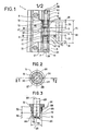
- the invention relates to a hinge 1 for door or window comprising two blades 2 and 3, one of which is fixed to the frame of the door or window, the other being made integral with the opening.
- Figure 1 chosen for convenience, shows a hinge whose blades have a configuration specific to their use.
- the blade 2 is provided with two end knuckles 4 and 5 arranged one above the other and has a bore, respectively 6 and 7.
- the axis of the bore 6 of the knuckle 4 is located in the vertical extension of the axis of the bore 7 of the knuckle 5.
- the set of external dimensions of the end knuckles 4 and 5 can be variable and depends on the stresses exerted on the hinge. These dimensions can easily be determined by a person skilled in the art.
- This central knuckle 8 has a bore 9 opening into a housing 11 in which is placed a plug 12 .
- the central knuckle 8 has two housings 11 located on either side of the bore 9.
- the plug 12 is provided with a flange 13 abutting on the end face 14 of the knuckle central 8.
- the distance 15 separating the two end knuckles 4 and 5 of the blade 2 corresponds to the sum of the length of the central knuckle 8 and either once or twice the thickness 16 of the flanges 13 so as to allow the engagement of the central knuckle 8 provided with its plug (s) 12 between the two end knuckles 4 and 5, the axis of the bore 9 then being situated in the same vertical extension as the axes of the bores 6 and 7.
- the spindle 17 comprises two peripheral grooves 21.
- the jaws 19 are elastic metal strips.
- these jaws 19 are made of elastic plastic. If necessary, provision may be made for the entire plug 12 to be made of plastic.
- the plug 12 can be provided with a variable number of vertical beads 24 situated on its external surface. These vertical beads 24, having the effect of producing a tightening between the housing 11 and the plug 12, avoid an unexpected displacement of the latter in an axial direction during assembly.
- a chamfer 25 located at the end 18 of the plug 12 facilitates the engagement of the latter in its corresponding housing 11.
- the jaws 19, integral with the end 18, substantially take the form of a cylinder in which vertical cuts were made 26. According to one embodiment of the present invention, these jaws 19 are four in number perfectly symmetrical with respect to the vertical axis 22 of the plug 12. It is quite obvious that by increasing the number of vertical cuts 26, it is possible to increase the number of jaws 19, but the latter will then be of lower strength.
- a claw 20, located at the end of a jaw 19, consists of a bead taking the form of an arc of a circle and located at the free end of the jaw 19, this claw 20 being directed towards the inside of the plug 12.
- the internal diameter 27 of the circle 28 formed by the set of claws 20 is less than the diameter of the pin 17.
- the jaws 19 define an internal space of cylindrical shape with a diameter equal to the internal diameter 29 of the bore of the plug 12.
- the external diameter of the jaws 19 is equal to the internal diameter of the bore 31 of the housing 11 reduced by at least twice the thickness 30 of the claws 20.
- an empty space 10 is obtained between the bore 31 of the housing 11 and the outside diameter of the jaws 19. Therefore, it will be possible for the jaws 19, due to their elasticity, to deviate enough to cause the erasure of the claws 20 during the passage of the spindle 17.
- Figure 4 shows the arrangement of the pin 17 and the plug 12 during assembly.
- the spindle 17 exerts, by its outside diameter, a pressure on the claws 20, this pressure having the effect of spreading the jaws 19 by elastic deformation of the material at their connection on the end 18 of the plug 12.
- a pressure on the claws 20 By an effect lever arm, due to the length of the jaws 19, the force exerted on the claws 20 is considerably reduced. This results in better wear resistance.
- the length of the jaws 19 can vary. However, the sum of their length 32 and the height 33 of the body 34 of the plug 12 must be equal to or less than the height 35 of the housing 11.
- Figure 5 shows the elements of Figure 4, the pin 17 being in its position mounted in the hinge 1.
- the claws 20 of the plug 12 are in their penetrating position in the peripheral groove 21 ensuring perfect retention of the pin 17 to any displacement of the latter in its axial direction, it being understood that if the central knuckle 8 has two plugs 12, the claws 20 of the latter engage in the respective peripheral grooves 21. It should be noted that the maintenance and guiding of this spindle 17 in directions perpendicular to its axis are provided by the bore 9 of the central knuckle 8 and the bores 6 and 7 of the end knuckles 4 and 5.
- the lateral sides 36 and 37 are of frustoconical shape so as to facilitate the release of the spindle 17 from the prongs 20 without deterioration of these or of the jaws 19.
- the peripheral grooves 21 have a section of a semicircle.
- the present invention also relates to the hinges comprising two blades, each of which is provided with only one knuckle.
- one of the knuckles may comprise a single housing 11, and therefore, a single plug 12, disposed on the side of the junction of the two knuckles. It is also possible that the same knuckle has two housings 11 and two plugs 12, but in this case, it is preferable to engage the second plug 12 after the spindle 17 has been put in place.
- the procedure is as follows: the plugs 12 are first engaged in the housings 11 of the central knuckle 8 of the blade 3, the central knuckle 8, surmounted by the flanges 13 of the plugs 12, is disposed between the end knuckles 4 and 5 of the blade 2 so that the bores 6, 7 and 9 are located in the vertical extension of one another. Then, the spindle 17 is engaged by its end 38 in the end knuckle 5 and in the central knuckle 8 until it meets the claws 20 of the first plug 12. We exerts pressure on the end 39 of the spindle 17 causing the jaws 19 to separate and the claws 20 to be erased. This mounting will be facilitated by means of a chamfer 40 provided at the end 38 of the spindle 17.
- peripheral grooves 21 To ensure the penetrating position of the claws 20 of the two plugs 12 in their respective peripheral grooves 21, provision is made for these peripheral grooves 21 to be located at locations such that the end 39 of the pin 17 is flush with the face lower 41 of the end knuckle 5.
- the different elements of the hinge 1 are symmetrical with respect to a horizontal median plane 42.
- the pin 17 can be engaged both from the bottom towards the top only from the top to the bottom.
Claims (5)
Priority Applications (1)
| Application Number | Priority Date | Filing Date | Title |
|---|---|---|---|
| AT87440057T ATE59083T1 (de) | 1986-09-30 | 1987-09-18 | Tuer- oder fensterscharnier mit axialer blockierung des bolzens. |
Applications Claiming Priority (2)
| Application Number | Priority Date | Filing Date | Title |
|---|---|---|---|
| FR8613785 | 1986-09-30 | ||
| FR8613785A FR2604475A1 (fr) | 1986-09-30 | 1986-09-30 | Paumelle a blocage axial de la broche pour porte ou fenetre |
Publications (2)
| Publication Number | Publication Date |
|---|---|
| EP0263769A1 EP0263769A1 (de) | 1988-04-13 |
| EP0263769B1 true EP0263769B1 (de) | 1990-12-12 |
Family
ID=9339511
Family Applications (1)
| Application Number | Title | Priority Date | Filing Date |
|---|---|---|---|
| EP87440057A Expired - Lifetime EP0263769B1 (de) | 1986-09-30 | 1987-09-18 | Tür- oder Fensterscharnier mit axialer Blockierung des Bolzens |
Country Status (12)
| Country | Link |
|---|---|
| US (1) | US4864692A (de) |
| EP (1) | EP0263769B1 (de) |
| JP (1) | JPS63156184A (de) |
| KR (1) | KR910001456B1 (de) |
| CN (1) | CN1008928B (de) |
| AT (1) | ATE59083T1 (de) |
| DE (1) | DE3766683D1 (de) |
| ES (1) | ES2019967B3 (de) |
| FR (1) | FR2604475A1 (de) |
| GR (1) | GR3001591T3 (de) |
| HK (1) | HK77791A (de) |
| SG (1) | SG77091G (de) |
Cited By (1)
| Publication number | Priority date | Publication date | Assignee | Title |
|---|---|---|---|---|
| EP4324696A1 (de) * | 2022-08-19 | 2024-02-21 | Hymer GmbH & Co. KG | Freizeitfahrzeug mit einer nasszelle und einem schwenkachsenlager |
Families Citing this family (13)
| Publication number | Priority date | Publication date | Assignee | Title |
|---|---|---|---|---|
| JPH0667013B2 (ja) * | 1988-03-16 | 1994-08-24 | 松下電器産業株式会社 | 遠隔制御装置 |
| US5711053A (en) * | 1996-03-26 | 1998-01-27 | Hafner; Bernhard T. W. | Un-lockable hinge pintle lock and method of use |
| DE19632027A1 (de) * | 1996-08-08 | 1998-02-12 | Scharwaechter Gmbh Co Kg | Trennbares Kraftwagentürscharnier |
| CA2237976A1 (en) | 1998-06-15 | 1999-12-15 | Christian Guillemette | Lockable hinge device |
| AT409782B (de) * | 1998-09-03 | 2002-11-25 | Roto Frank Eisenwaren | Ladenbeschlag |
| BE1014539A3 (nl) * | 2001-12-13 | 2003-12-02 | Parys Remi E Van | Scharnier en scharnierdeel daarvoor. |
| US6741472B1 (en) * | 2002-11-06 | 2004-05-25 | Walkabout Computers, Inc. | Secure hinge mechanism for portable computer |
| ES2323822B1 (es) * | 2005-07-21 | 2010-06-01 | Alutec S.R.L. | Bisagra para cerrajeria. |
| ITPD20050226A1 (it) * | 2005-07-21 | 2007-01-22 | Alutec Srl | Cerniera per serramenti |
| CN101169019B (zh) * | 2007-11-27 | 2011-08-31 | 联程机械(宁波)有限公司 | 一种门窗铰链 |
| EP2085549B1 (de) | 2008-01-31 | 2012-03-14 | SAVIO S.p.A. | Ein Scharnier für Türen oder Fenster |
| DE202013002821U1 (de) * | 2013-03-25 | 2014-06-27 | Dieter Ramsauer | Scharnier |
| EP3498956B1 (de) | 2017-12-15 | 2024-03-27 | MAGNA STEYR Fahrzeugtechnik GmbH & Co KG | Scharnier |
Family Cites Families (10)
| Publication number | Priority date | Publication date | Assignee | Title |
|---|---|---|---|---|
| US2797433A (en) * | 1953-09-17 | 1957-07-02 | Hager & Sons Hinge Mfg | Door hinges |
| US3135013A (en) * | 1961-03-10 | 1964-06-02 | Stanley Works | Hinge with pin retaining means |
| US3152356A (en) * | 1961-08-31 | 1964-10-13 | Stanley Works | Hinge with non-rising pin |
| DE2750310A1 (de) * | 1977-11-10 | 1979-05-17 | Dorma Baubeschlag | Fuer tueren u.dgl. bestimmtes scharnierband |
| US4135273A (en) * | 1978-01-23 | 1979-01-23 | Holmes Stannard D | Hinge with interfitting locking means |
| DE7914232U1 (de) * | 1979-05-17 | 1979-08-23 | Paul Hettich & Co, 4983 Kirchlengern | Mit einer glastuer versehener schrank |
| DE3401245A1 (de) * | 1984-01-16 | 1985-07-18 | Lunke & Sohn Gmbh, 5810 Witten | Tuerscharnier fuer ein kraftfahrzeug |
| DE8410106U1 (de) * | 1984-04-02 | 1984-07-19 | Rittal-Werk Rudolf Loh Gmbh & Co Kg, 6348 Herborn | Schaltschrank mit am Schrankkorpus angelenkter Schranktür |
| DE8434089U1 (de) * | 1984-11-22 | 1985-02-21 | Siegenia-Frank Kg, 5900 Siegen | Scharnier fuer fenster und tueren |
| FR2573808A1 (fr) * | 1984-11-29 | 1986-05-30 | Rado Montres Sa | Charniere notamment pour bracelet |
-
1986
- 1986-09-30 FR FR8613785A patent/FR2604475A1/fr active Granted
-
1987
- 1987-09-18 AT AT87440057T patent/ATE59083T1/de active
- 1987-09-18 EP EP87440057A patent/EP0263769B1/de not_active Expired - Lifetime
- 1987-09-18 DE DE8787440057T patent/DE3766683D1/de not_active Expired - Fee Related
- 1987-09-18 ES ES87440057T patent/ES2019967B3/es not_active Expired - Lifetime
- 1987-09-28 US US07/101,639 patent/US4864692A/en not_active Expired - Fee Related
- 1987-09-30 JP JP62244428A patent/JPS63156184A/ja active Pending
- 1987-09-30 CN CN87106636A patent/CN1008928B/zh not_active Expired
- 1987-09-30 KR KR1019870010901A patent/KR910001456B1/ko not_active IP Right Cessation
-
1991
- 1991-03-12 GR GR91400304T patent/GR3001591T3/el unknown
- 1991-09-17 SG SG770/91A patent/SG77091G/en unknown
- 1991-10-03 HK HK777/91A patent/HK77791A/xx unknown
Cited By (1)
| Publication number | Priority date | Publication date | Assignee | Title |
|---|---|---|---|---|
| EP4324696A1 (de) * | 2022-08-19 | 2024-02-21 | Hymer GmbH & Co. KG | Freizeitfahrzeug mit einer nasszelle und einem schwenkachsenlager |
Also Published As
| Publication number | Publication date |
|---|---|
| FR2604475B1 (de) | 1994-07-13 |
| SG77091G (en) | 1992-03-20 |
| FR2604475A1 (fr) | 1988-04-01 |
| GR3001591T3 (en) | 1992-11-23 |
| CN87106636A (zh) | 1988-07-13 |
| HK77791A (en) | 1991-10-11 |
| KR910001456B1 (ko) | 1991-03-07 |
| DE3766683D1 (de) | 1991-01-24 |
| US4864692A (en) | 1989-09-12 |
| KR880004195A (ko) | 1988-06-02 |
| EP0263769A1 (de) | 1988-04-13 |
| ATE59083T1 (de) | 1990-12-15 |
| JPS63156184A (ja) | 1988-06-29 |
| CN1008928B (zh) | 1990-07-25 |
| ES2019967B3 (es) | 1991-07-16 |
Similar Documents
| Publication | Publication Date | Title |
|---|---|---|
| EP0263769B1 (de) | Tür- oder Fensterscharnier mit axialer Blockierung des Bolzens | |
| EP0793024B1 (de) | Verbindungs- und Verriegelungsvorrichtung für teleskopische Rohre | |
| EP0886712A1 (de) | Schutzvorrichtung und führung eines langen teiles, das mit einem schanier an zwei mieinander schwenkbar verbundenen festen elementen befestigt ist, und industrielle anwendung hierfür | |
| FR2623553A1 (fr) | Charniere a engagement lateral pour vantail et analogues | |
| FR2721377A1 (fr) | Dispositif de connexion à traction pour assembler deux profilés. | |
| FR2761720A1 (fr) | Ferrure de verrouillage pour ouvrant coulissant | |
| CA1292845C (fr) | Paumelle a blocage axial de la broche pour porte ou fenetre | |
| FR2619292A1 (fr) | Fermoir pour bracelet | |
| EP0892296A1 (de) | Federscharnier für einen flachen Brillenbügel | |
| FR2614921A1 (fr) | Dispositif de securite a l'arrachement et a l'enfoncement d'une piece emmanchee dans une autre piece, et ensemble formant serrure de surete equipe de ce dispositif | |
| EP0354838B1 (de) | Sicherheitszylinder für ein Schloss und entsprechender Schlüssel | |
| CH645812A5 (en) | Ski safety binding | |
| FR2650920A1 (fr) | Connecteur auto-denudant a elements conducteurs susceptibles de s'entrecroiser | |
| EP0700479B1 (de) | Schlüssel mit zwei abschrägungen am ende für ein sicherheitzylinderschloss und zylinderschloss dafür | |
| FR2785341A1 (fr) | Dispositif pour l'immobilisation reversible d'un arbre par une clavette tangentielle. | |
| FR2573468A1 (fr) | Charniere pour fenetres et pour portes comportant une broche bloquee par un dispositif d'arret elastique | |
| FR2789748A1 (fr) | Dispositif de connexion de profiles | |
| FR2514434A1 (fr) | Bride de raccordement de deux elements | |
| EP1709344B1 (de) | Vorrichtung zur verbindung von zwei kabeln während der herstellung der maschen eines sicherheitsnetzes | |
| FR2775716A1 (fr) | Cylindre de surete a barillet double | |
| FR2865232A1 (fr) | Fourreau cache-paumelle reglable en hauteur. | |
| EP1867882B1 (de) | Verankerungsvorrichtung mit Flügeldübeln | |
| EP0377372B1 (de) | Einstellbares Schliessblech für den Aufbau auf einen Rahmen und damit versehenes Schloss | |
| FR2844695A1 (fr) | Appareil electromenager a panneaux articules | |
| FR2801187A1 (fr) | Agrafe medicale pour maintenir au moins deux positions d'os l'une par rapport a l'autre |
Legal Events
| Date | Code | Title | Description |
|---|---|---|---|
| PUAI | Public reference made under article 153(3) epc to a published international application that has entered the european phase |
Free format text: ORIGINAL CODE: 0009012 |
|
| AK | Designated contracting states |
Kind code of ref document: A1 Designated state(s): AT BE CH DE ES GB GR IT LI NL SE |
|
| 17P | Request for examination filed |
Effective date: 19880428 |
|
| 17Q | First examination report despatched |
Effective date: 19890911 |
|
| GRAA | (expected) grant |
Free format text: ORIGINAL CODE: 0009210 |
|
| AK | Designated contracting states |
Kind code of ref document: B1 Designated state(s): AT BE CH DE ES GB GR IT LI NL SE |
|
| REF | Corresponds to: |
Ref document number: 59083 Country of ref document: AT Date of ref document: 19901215 Kind code of ref document: T |
|
| REF | Corresponds to: |
Ref document number: 3766683 Country of ref document: DE Date of ref document: 19910124 |
|
| ITF | It: translation for a ep patent filed |
Owner name: BUGNION S.P.A. |
|
| GBT | Gb: translation of ep patent filed (gb section 77(6)(a)/1977) | ||
| PGFP | Annual fee paid to national office [announced via postgrant information from national office to epo] |
Ref country code: SE Payment date: 19910906 Year of fee payment: 5 |
|
| PGFP | Annual fee paid to national office [announced via postgrant information from national office to epo] |
Ref country code: GB Payment date: 19910909 Year of fee payment: 5 |
|
| PGFP | Annual fee paid to national office [announced via postgrant information from national office to epo] |
Ref country code: AT Payment date: 19910910 Year of fee payment: 5 |
|
| PLBI | Opposition filed |
Free format text: ORIGINAL CODE: 0009260 |
|
| PLAB | Opposition data, opponent's data or that of the opponent's representative modified |
Free format text: ORIGINAL CODE: 0009299OPPO |
|
| PGFP | Annual fee paid to national office [announced via postgrant information from national office to epo] |
Ref country code: CH Payment date: 19910923 Year of fee payment: 5 |
|
| PGFP | Annual fee paid to national office [announced via postgrant information from national office to epo] |
Ref country code: ES Payment date: 19910927 Year of fee payment: 5 |
|
| ITTA | It: last paid annual fee | ||
| PGFP | Annual fee paid to national office [announced via postgrant information from national office to epo] |
Ref country code: NL Payment date: 19910930 Year of fee payment: 5 Ref country code: GR Payment date: 19910930 Year of fee payment: 5 |
|
| 26 | Opposition filed |
Opponent name: SIEGENIA-FRANK KG Effective date: 19910909 |
|
| PGFP | Annual fee paid to national office [announced via postgrant information from national office to epo] |
Ref country code: BE Payment date: 19911106 Year of fee payment: 5 |
|
| R26 | Opposition filed (corrected) |
Opponent name: SIEGENIA-FRANK KG Effective date: 19910907 |
|
| NLR1 | Nl: opposition has been filed with the epo |
Opponent name: SIEGENIA-FRANK KG |
|
| REG | Reference to a national code |
Ref country code: GR Ref legal event code: FG4A Free format text: 3001591 |
|
| PG25 | Lapsed in a contracting state [announced via postgrant information from national office to epo] |
Ref country code: GB Effective date: 19920918 Ref country code: AT Effective date: 19920918 |
|
| PG25 | Lapsed in a contracting state [announced via postgrant information from national office to epo] |
Ref country code: SE Effective date: 19920919 Ref country code: ES Free format text: LAPSE BECAUSE OF THE APPLICANT RENOUNCES Effective date: 19920919 |
|
| PG25 | Lapsed in a contracting state [announced via postgrant information from national office to epo] |
Ref country code: LI Effective date: 19920930 Ref country code: CH Effective date: 19920930 Ref country code: BE Effective date: 19920930 |
|
| BERE | Be: lapsed |
Owner name: FERCO INTERNATIONAL USINE DE FERRURES DE BATIMENT Effective date: 19920930 |
|
| PG25 | Lapsed in a contracting state [announced via postgrant information from national office to epo] |
Ref country code: GR Free format text: THE PATENT HAS BEEN ANNULLED BY A DECISION OF A NATIONAL AUTHORITY Effective date: 19930331 |
|
| PG25 | Lapsed in a contracting state [announced via postgrant information from national office to epo] |
Ref country code: NL Effective date: 19930401 |
|
| GBPC | Gb: european patent ceased through non-payment of renewal fee |
Effective date: 19920918 |
|
| NLV4 | Nl: lapsed or anulled due to non-payment of the annual fee | ||
| REG | Reference to a national code |
Ref country code: CH Ref legal event code: PL |
|
| PLBN | Opposition rejected |
Free format text: ORIGINAL CODE: 0009273 |
|
| STAA | Information on the status of an ep patent application or granted ep patent |
Free format text: STATUS: OPPOSITION REJECTED |
|
| 27O | Opposition rejected |
Effective date: 19930317 |
|
| REG | Reference to a national code |
Ref country code: GR Ref legal event code: MM2A Free format text: 3001591 |
|
| EUG | Se: european patent has lapsed |
Ref document number: 87440057.5 Effective date: 19930406 |
|
| PGFP | Annual fee paid to national office [announced via postgrant information from national office to epo] |
Ref country code: DE Payment date: 19981123 Year of fee payment: 12 |
|
| REG | Reference to a national code |
Ref country code: ES Ref legal event code: FD2A Effective date: 19991007 |
|
| PG25 | Lapsed in a contracting state [announced via postgrant information from national office to epo] |
Ref country code: DE Free format text: LAPSE BECAUSE OF NON-PAYMENT OF DUE FEES Effective date: 20000701 |
|
| PG25 | Lapsed in a contracting state [announced via postgrant information from national office to epo] |
Ref country code: IT Free format text: LAPSE BECAUSE OF NON-PAYMENT OF DUE FEES;WARNING: LAPSES OF ITALIAN PATENTS WITH EFFECTIVE DATE BEFORE 2007 MAY HAVE OCCURRED AT ANY TIME BEFORE 2007. THE CORRECT EFFECTIVE DATE MAY BE DIFFERENT FROM THE ONE RECORDED. Effective date: 20050918 |