EP0258284B1 - Anlage zum beidseitigen beschichten und trocknen von leiterplatten od. dgl. - Google Patents
Anlage zum beidseitigen beschichten und trocknen von leiterplatten od. dgl. Download PDFInfo
- Publication number
- EP0258284B1 EP0258284B1 EP87900800A EP87900800A EP0258284B1 EP 0258284 B1 EP0258284 B1 EP 0258284B1 EP 87900800 A EP87900800 A EP 87900800A EP 87900800 A EP87900800 A EP 87900800A EP 0258284 B1 EP0258284 B1 EP 0258284B1
- Authority
- EP
- European Patent Office
- Prior art keywords
- coating
- sides
- drying
- conductor
- coated
- Prior art date
- Legal status (The legal status is an assumption and is not a legal conclusion. Google has not performed a legal analysis and makes no representation as to the accuracy of the status listed.)
- Expired - Lifetime
Links
- 239000011248 coating agent Substances 0.000 title claims abstract description 34
- 238000000576 coating method Methods 0.000 title claims abstract description 34
- 238000001035 drying Methods 0.000 title claims abstract description 18
- 238000009434 installation Methods 0.000 title claims 4
- 238000000034 method Methods 0.000 claims abstract description 8
- 239000007788 liquid Substances 0.000 claims abstract 3
- 239000004020 conductor Substances 0.000 claims description 20
- 239000002966 varnish Substances 0.000 claims description 3
- 238000003780 insertion Methods 0.000 abstract description 2
- 230000037431 insertion Effects 0.000 abstract description 2
- 230000007306 turnover Effects 0.000 abstract 2
- 239000000463 material Substances 0.000 abstract 1
- 238000005266 casting Methods 0.000 description 3
- 238000011161 development Methods 0.000 description 2
- 230000018109 developmental process Effects 0.000 description 2
- 238000010422 painting Methods 0.000 description 1
- 238000007669 thermal treatment Methods 0.000 description 1
Images
Classifications
-
- B—PERFORMING OPERATIONS; TRANSPORTING
- B05—SPRAYING OR ATOMISING IN GENERAL; APPLYING FLUENT MATERIALS TO SURFACES, IN GENERAL
- B05C—APPARATUS FOR APPLYING FLUENT MATERIALS TO SURFACES, IN GENERAL
- B05C9/00—Apparatus or plant for applying liquid or other fluent material to surfaces by means not covered by any preceding group, or in which the means of applying the liquid or other fluent material is not important
- B05C9/04—Apparatus or plant for applying liquid or other fluent material to surfaces by means not covered by any preceding group, or in which the means of applying the liquid or other fluent material is not important for applying liquid or other fluent material to opposite sides of the work
-
- G—PHYSICS
- G03—PHOTOGRAPHY; CINEMATOGRAPHY; ANALOGOUS TECHNIQUES USING WAVES OTHER THAN OPTICAL WAVES; ELECTROGRAPHY; HOLOGRAPHY
- G03F—PHOTOMECHANICAL PRODUCTION OF TEXTURED OR PATTERNED SURFACES, e.g. FOR PRINTING, FOR PROCESSING OF SEMICONDUCTOR DEVICES; MATERIALS THEREFOR; ORIGINALS THEREFOR; APPARATUS SPECIALLY ADAPTED THEREFOR
- G03F7/00—Photomechanical, e.g. photolithographic, production of textured or patterned surfaces, e.g. printing surfaces; Materials therefor, e.g. comprising photoresists; Apparatus specially adapted therefor
- G03F7/16—Coating processes; Apparatus therefor
-
- H—ELECTRICITY
- H05—ELECTRIC TECHNIQUES NOT OTHERWISE PROVIDED FOR
- H05K—PRINTED CIRCUITS; CASINGS OR CONSTRUCTIONAL DETAILS OF ELECTRIC APPARATUS; MANUFACTURE OF ASSEMBLAGES OF ELECTRICAL COMPONENTS
- H05K3/00—Apparatus or processes for manufacturing printed circuits
- H05K3/0091—Apparatus for coating printed circuits using liquid non-metallic coating compositions
-
- H—ELECTRICITY
- H05—ELECTRIC TECHNIQUES NOT OTHERWISE PROVIDED FOR
- H05K—PRINTED CIRCUITS; CASINGS OR CONSTRUCTIONAL DETAILS OF ELECTRIC APPARATUS; MANUFACTURE OF ASSEMBLAGES OF ELECTRICAL COMPONENTS
- H05K3/00—Apparatus or processes for manufacturing printed circuits
- H05K3/22—Secondary treatment of printed circuits
- H05K3/227—Drying of printed circuits
-
- H—ELECTRICITY
- H05—ELECTRIC TECHNIQUES NOT OTHERWISE PROVIDED FOR
- H05K—PRINTED CIRCUITS; CASINGS OR CONSTRUCTIONAL DETAILS OF ELECTRIC APPARATUS; MANUFACTURE OF ASSEMBLAGES OF ELECTRICAL COMPONENTS
- H05K2203/00—Indexing scheme relating to apparatus or processes for manufacturing printed circuits covered by H05K3/00
- H05K2203/15—Position of the PCB during processing
- H05K2203/1509—Horizontally held PCB
-
- H—ELECTRICITY
- H05—ELECTRIC TECHNIQUES NOT OTHERWISE PROVIDED FOR
- H05K—PRINTED CIRCUITS; CASINGS OR CONSTRUCTIONAL DETAILS OF ELECTRIC APPARATUS; MANUFACTURE OF ASSEMBLAGES OF ELECTRICAL COMPONENTS
- H05K2203/00—Indexing scheme relating to apparatus or processes for manufacturing printed circuits covered by H05K3/00
- H05K2203/15—Position of the PCB during processing
- H05K2203/1563—Reversing the PCB
-
- Y—GENERAL TAGGING OF NEW TECHNOLOGICAL DEVELOPMENTS; GENERAL TAGGING OF CROSS-SECTIONAL TECHNOLOGIES SPANNING OVER SEVERAL SECTIONS OF THE IPC; TECHNICAL SUBJECTS COVERED BY FORMER USPC CROSS-REFERENCE ART COLLECTIONS [XRACs] AND DIGESTS
- Y10—TECHNICAL SUBJECTS COVERED BY FORMER USPC
- Y10S—TECHNICAL SUBJECTS COVERED BY FORMER USPC CROSS-REFERENCE ART COLLECTIONS [XRACs] AND DIGESTS
- Y10S118/00—Coating apparatus
- Y10S118/04—Curtain coater
Definitions
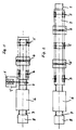
- the object of the invention is to subject both sides of a circuit board to the same thermal treatment.
- the transparent slide 3 has a turning device and a side plate holder. He thus travels through the cast film of a coating device 4, whereby he provides one side of the printed circuit board 1 with a screen.
- This transparent carriage 3 with the circuit board 1 coated on one side is stopped on the transparent web and turned in the device 5. As a result, the side of the circuit board that has not yet been coated comes up.
- the transport carriage 3 now travels back through the same coating device 4 or through the cast film thereof, which coats the second side of the printed circuit board 1. Now both sides of the circuit board 1 are provided with the desired coating, which cannot be damaged because the circuit board is only held by the holding device of the transport carriage 3 is clamped on the two outer edges.
- the printed circuit board coated on both sides is introduced into the dryer 6 on the transport path 2. Both sides of the circuit board dry evenly at the same temperature conditions. In this way, a coating device (casting machine) and a drying device can be saved. Following the drying device 6, a discharge belt 7 is seen which leads to a stacker 8 or a cassette.
- the circuit board 1 is not supplied from the side, as in FIG. 1, but at the front end of the transport path 2 of the system by a corresponding device.
- the circuit board 1 moves with its holding device through a first coating device (casting machine) 4 and then moves on to a turning device 5.
- This causes the circuit board with its coated side to go down, while the still uncoated side of the circuit board In this state, the transparent slide moves with the circuit board through the second coating device or casting machine 4 '.
- Both sides of the conductor plate 1 are now provided with the coating, and in this state it is introduced into the common drying device 6.
- the circuit board is dried in the same way as in the system according to FIG. 1, from where it is brought to a discharge or stacking or to another location.
- the system according to FIG. 2 has the advantage that it has no laterally protruding devices as in FIG. 1.
Landscapes
- Engineering & Computer Science (AREA)
- Manufacturing & Machinery (AREA)
- Microelectronics & Electronic Packaging (AREA)
- Physics & Mathematics (AREA)
- General Physics & Mathematics (AREA)
- Non-Metallic Protective Coatings For Printed Circuits (AREA)
- Coating Apparatus (AREA)
Description
- Zum beidseitigen Anstreichen von Platten ist aus der DE-A-1 752079 bekannt, jede Platte auf einem Rollengang durch eine Beschichtungsvorrichtung zu transportieren und auf der einen Seite zu beschichten. Anschließend wird die einseitig beschichtete Platte durch eine Trocknungsvorrichtung transportiert, um die Beschichtung zu trocknen. Nach erfolgter Trocknung wird die Platte in einer Wendevorrichtung um 180° gewendet, so daß die andere, noch unbeschichtete Seite nach oben zeigt, während die getrocknete und damit belastbare Plattenseite auf dem Rollengang aufliegt. Nunmehr wird die andere Plattenseite in derselben Weise und in denselben Vorrichtungen wie zuvor die eine Plattenseite beschichtet und getrocknet. Abgesehen davon, daß eine derartige, sukzesive Behandlung beider Plattenseiten zeitaufwendig ist, besteht ein wesentlicher Nachteil im Falle der Beschichtung mit lichtempfindlichem Lack bei Leiterplatten darin, daß die bereits getrocknete Plattenseite während der Trocknung der anderen Plattenseite nochmals der Trocknung unterworfen wird.
- Die Aufgabe der Erfindung besteht demgegenüber darin, beide Seiten einer Leiterplatte derselben thermischen Behandlung zu unterwerfen.
- Diese Aufgabe wird erfindungsgemäß bei einem Verfahren gemäß den kennzeichnenden Merkmalen des Patentanspruchs 1 und bei Anlagen gemäß den kennzeichnenden Merkmalen der Patentansprüche 4 und 5 gelöst.
- Vorteilhafte Weiterbildungen und Ausgestaltungen des erfindungsgemäßen Verfahrens ergeben sich aus den Patentansprüchen 2 und 3.
- Vorteilhafte Ausgestaltungen und Weiterbildungen der erfindungsgemäßen Anlagen ergeben sich aus dem Patentanspruch 6.
- Die Erfindung wird im folgenden anhand zweier Ausführungsformen in den Zeichnungen näher erläutert. Es zeigt:
- Fig. 1 eine Draufsicht auf eine Beschichtungsanlage mit seitlicher Plattenzuführung und einer einzigen Beschichtungsvorrichtung, und
- Fig. 2 eine Draufsicht auf eine alternative Beschichtungsanlage mit zwei Beschichtungsvorrichtungen und mit Plattenzuführung an einem Ende der Anlage.
- Bei der in Fig. 1 dargestellten Beschichtungsanlage wird von einer Platteneinlagestelle 1′ eine Leiterplatte 1 von der Seite her einer Transportbahn 2 zugeführt und auf eine fahrbare Transportvorrichtung bzw. auf einen Transportschlitten 3 gelegt. Oer Transpartschlitten 3 hat eine Wendevorrichtung und eine seitliche Plattenhalterung. Damit fährt er durch den Gießfilm einer Beschichtungsvorrichtung 4, wodurch er die eine Seite der Leiterplatte 1 mit einer Beschirhtung versieht.
- Dieser Transpartschlitten 3 mit der einseitig beschichteten Leiterplatte 1 wird auf der Transpartbahn gestoppt und in der Vorrichtung 5 gewendet. Dadurch kommt die noch nicht beschichtete Plattenseite der Leiterplatte nach oben.
- In diesem Zustand fährt nun der Transportschlitten 3 zurück durch die gleiche Beschichtungsvorrichtung 4 bzw. durch den Gießfilm derselben, welcher die zweite Seite der Leiterplatte 1 beschichtet. Nunmehr sind beide Seiten der Leiterplatte 1 mit der gewünschten Beschichtung versehen, welche nicht beschädigt werden können, weil die Leiterplatte von der Haltevorrichtung des Transportschlittens 3 nur an den beiden äuBeren Rändern festgeklemmt ist.
- Nunmehr wird die beidseitig beschichtete Leiterplatte auf der Transportbahn 2 in den Trockner 6 eingeführt. Beide Seiten der Leiterplatte trocknen darin gleichmäßig bei gleichen Temperaturverhältnissen. Auf diese Weise können eine Beschichtungsvorrichtung (Gießmaschine) und eine Trocknungsvorrichtunn eingespart werden. Im Anschluß an die Trocknungsvorrichtung 6 ist ein Auslaufband 7 vargesehen, das zu einem Abstapler 8 bzw. einer Kassette führt.
- Bei der Anlage gemäß Fig. 2 wird die Leiterplatte 1 nicht von der Seite her, wie in Fig. 1, sondern am vorderen Ende der Transportbahn 2 der Anlage durch eine entsprechende Vorrichtung zugeführt. Auf dem Transport-schlitten 3 fährt die Leiterplatte 1 mit ihrer Haltevorrichtung durch eine erste Beschichtungsvorrichtung (Gießmaschine) 4 und bewegt sich dann weiter bis zu einer Wendevorrichtung 5. Dadurch gelangt die Leiterplatte mit ihrer beschichteten Seite nach unten, während die noch unbeschichtete Seite der Leiterplatte nach oben gelangt, In diesem Zustand fährt der Transpartschlitten mit der Leiterplatte durch die zweite Beschichtungsvorrichtung oder Gießmaschine 4′. Es sind jetzt beide Seiten der Laiterplatte 1 mit der Beschichtung versehen, und in diesem Zustand wird sie in die gemeinsame Trocknungsvorrichtung 6 eingeführt. Die Trocknung der Leiterplatte erfolgt darin wie bei der Anlage gemäß Fig. 1, von wo aus sie zu einer Ableitung oder Abstapelung oder an eine sonstige Stelle gebracht wird. Die Anlage gemäß Fig. 2 hat den Vorteil, daß sie keine seitlich vorstehenden Vorrichtungen hat wie bei Fig. 1.
Claims (6)
wobei jede Leiterplatte (1) bei ihrem Transport nur an den beiden äußeren Rändern gehalten wird, daß die andere Seite jeder Leiterplatte (1) beschichtet wird, noch während die bereits beschichtete Seite ungetrocknet ist, und daß erst nach dem Beschichten der anderen Seite die Leiterplatte (1) durch die Trocknungsvorrichtung (6) transportiert wird, wo beide Seiten jeder Leiterplatte (1) gleichzeitig bei gleichen Temperaturverhältnissen getrocknet werden.
Priority Applications (1)
| Application Number | Priority Date | Filing Date | Title |
|---|---|---|---|
| AT87900800T ATE75364T1 (de) | 1986-01-27 | 1987-01-22 | Anlage zum beidseitigen beschichten und trocknen von leiterplatten od. dgl. |
Applications Claiming Priority (2)
| Application Number | Priority Date | Filing Date | Title |
|---|---|---|---|
| DE3602350 | 1986-01-27 | ||
| DE3602350A DE3602350C2 (de) | 1986-01-27 | 1986-01-27 | Verfahren und Anlage zum beidseitigen Beschichten von Platten mit flüssigem Beschichtungsmaterial |
Publications (2)
| Publication Number | Publication Date |
|---|---|
| EP0258284A1 EP0258284A1 (de) | 1988-03-09 |
| EP0258284B1 true EP0258284B1 (de) | 1992-04-22 |
Family
ID=6292695
Family Applications (1)
| Application Number | Title | Priority Date | Filing Date |
|---|---|---|---|
| EP87900800A Expired - Lifetime EP0258284B1 (de) | 1986-01-27 | 1987-01-22 | Anlage zum beidseitigen beschichten und trocknen von leiterplatten od. dgl. |
Country Status (4)
| Country | Link |
|---|---|
| US (2) | US4871584A (de) |
| EP (1) | EP0258284B1 (de) |
| DE (1) | DE3602350C2 (de) |
| WO (1) | WO1987004584A1 (de) |
Families Citing this family (33)
| Publication number | Priority date | Publication date | Assignee | Title |
|---|---|---|---|---|
| FR2623962B1 (fr) * | 1987-10-22 | 1994-07-08 | Grah Klaus | Procede et appareil pour le laquage electrostatique de panneaux de circuits imprimes |
| US5006432A (en) * | 1987-10-28 | 1991-04-09 | Kabushiki Kaisha Toshiba | Method for manufacturing a shadow mask |
| FR2630961B1 (fr) * | 1988-05-06 | 1990-09-07 | Michelin & Cie | Procede et appareil pour enduire de caoutchouc des fils deroules en parallele et produire ainsi une nappe |
| US5032426A (en) * | 1989-05-15 | 1991-07-16 | Enthone, Incorporated | Method and apparatus for applying liquid coatings on the surface of printed circuit boards |
| DE3937071A1 (de) * | 1989-11-07 | 1991-05-08 | Kopperschmidt Mueller & Co | Vorrichtung und verfahren zum beschichten von plattenfoermigen substraten, wie leiterplatten |
| US5188669A (en) * | 1991-02-22 | 1993-02-23 | Nordson Corporation | Circuit board coating apparatus with inverting pallet shuttle |
| US5240746A (en) * | 1991-02-25 | 1993-08-31 | Delco Electronics Corporation | System for performing related operations on workpieces |
| DE4107224C1 (de) * | 1991-03-07 | 1992-06-04 | Dupont De Nemours Gmbh, 6380 Bad Homburg, De | |
| DE4107464A1 (de) * | 1991-03-08 | 1992-09-10 | Schmid Gmbh & Co Geb | Verfahren und vorrichtung zum einseitigen behandeln von plattenfoermigen gegenstaenden |
| US5516545A (en) * | 1991-03-26 | 1996-05-14 | Sandock; Leonard R. | Coating processes and apparatus |
| US5538754A (en) * | 1991-03-26 | 1996-07-23 | Shipley Company Inc. | Process for applying fluid on discrete substrates |
| IT1252949B (it) * | 1991-09-30 | 1995-07-06 | Gisulfo Baccini | Procedimento per la lavorazione di circuiti tipo green-tape e dispositivo adottante tale procedimento |
| US5190793A (en) * | 1991-11-18 | 1993-03-02 | Delco Electronics Corporation | Refractory covercoat for semicondutor devices and methods of making and using the same |
| TW220028B (en) * | 1992-08-24 | 1994-02-01 | Ciba Geigy Ag | Method and apparatus for coating board-shaped articles, especially printed circuit boards |
| ATE133531T1 (de) * | 1992-09-28 | 1996-02-15 | Ciba Geigy Ag | Verfahren und vorrichtung zur beidseitigen beschichtung von plattenförmigem stückgut |
| US5462601A (en) * | 1993-07-07 | 1995-10-31 | E. I. Du Pont De Nemours And Company | Automated test panel spray/bake device |
| US5588996A (en) * | 1994-04-01 | 1996-12-31 | Argus International | Apparatus for spray coating flat surfaces |
| US5733376A (en) * | 1994-04-01 | 1998-03-31 | Argus International | Apparatus for spray coating opposing major surfaces of a workpiece |
| DE29508265U1 (de) * | 1995-05-22 | 1995-07-06 | Fa. Theodor Hymmen, 33613 Bielefeld | Vorrichtung zum Farbbeschichten sowie zum Vor- oder/und Nachbehandeln von Werkstücken |
| TW483940B (en) * | 1998-06-24 | 2002-04-21 | Ciba Sc Holding Ag | Method for coating printed circuit boards or similar substrates |
| DE10230648B4 (de) * | 2001-08-23 | 2004-08-12 | Deutsche Rockwool Mineralwoll Gmbh + Co Ohg | Palette zum Transport von Plattenstapeln und Transport-und/oder Verpackungseinheit |
| US20060273138A1 (en) * | 2005-06-07 | 2006-12-07 | Samsung Electronics Co., Ltd. | Soldering apparatus for printed circuit board, soldering method for printed circuit board and soldering cream printing unit for soldering printed circuit board |
| KR20130076246A (ko) * | 2011-12-28 | 2013-07-08 | 삼성전기주식회사 | 공통 모드 필터 및 그 제조 방법 |
| US9357686B2 (en) | 2013-11-14 | 2016-05-31 | Illinois Tool Works Inc. | Dispensing apparatus having substrate inverter system and clamping system, and method for dispensing a viscous material on a substrate |
| US20150128856A1 (en) * | 2013-11-14 | 2015-05-14 | Illinois Tool Works Inc. | Dispensing apparatus having transport system and method for transporting a substrate within the dispensing apparatus |
| US9662675B2 (en) * | 2014-07-31 | 2017-05-30 | Illinois Tool Works Inc. | External inverter system for variable substrate thickness and method for rotating a substrate |
| ITUB20159139A1 (it) * | 2015-12-21 | 2017-06-21 | Cefla S C | Impianto per la verniciatura orizzontale di porte sagomate |
| CN108557428A (zh) * | 2018-05-22 | 2018-09-21 | 麦格纳电子(张家港)有限公司 | 电路板双面涂覆用的翻板装置 |
| CN108499812A (zh) * | 2018-05-22 | 2018-09-07 | 麦格纳电子(张家港)有限公司 | 电路板双面涂覆用的生产系统 |
| CN108580198A (zh) * | 2018-05-22 | 2018-09-28 | 麦格纳电子(张家港)有限公司 | 一种电路板的双面涂覆工艺 |
| CN112218443B (zh) * | 2020-10-29 | 2025-06-20 | 飞毛腿电池有限公司 | 凹凸配治具及凹凸配贴片工艺 |
| CN112707134A (zh) * | 2020-12-31 | 2021-04-27 | 麦格纳电子(张家港)有限公司 | 一种用于喷涂机的电路板翻转装置 |
| CN114308555B (zh) * | 2021-12-06 | 2023-01-10 | 江苏圣奎节能科技有限公司 | 一种建筑节能保温板生产用双面抹灰装置及其操作方法 |
Family Cites Families (12)
| Publication number | Priority date | Publication date | Assignee | Title |
|---|---|---|---|---|
| US3361245A (en) * | 1966-01-13 | 1968-01-02 | Michael Ladney Jr. | Tape conveyor for spray painting |
| DE1752079A1 (de) * | 1968-03-30 | 1971-04-01 | Bedaux Gmbh Deutsche | Verfahren und Vorrichtung zum beiderseitigen Anstreichen von Platten |
| US3610397A (en) * | 1969-03-05 | 1971-10-05 | Epec Systems Corp | Method and apparatus for turning over a plate |
| US3777703A (en) * | 1972-06-02 | 1973-12-11 | Western Electric Co | Apparatus for supporting and rotating a workpiece |
| US3902453A (en) * | 1974-03-22 | 1975-09-02 | Indian Head Inc | Ultra high speed bottle coating system and process |
| JPS5430021A (en) * | 1977-08-11 | 1979-03-06 | Fuji Photo Film Co Ltd | Consecutive application of both sides |
| US4111155A (en) * | 1977-09-12 | 1978-09-05 | P. R. Mallory & Co., Inc. | Cathode coating apparatus |
| US4228582A (en) * | 1978-09-22 | 1980-10-21 | Tokyo Print Industry Co., Ltd. | Automatic production system for printed-wiring boards |
| JPS5833697B2 (ja) * | 1979-12-17 | 1983-07-21 | ヱム・セテツク株式会社 | フオトレジストの両面塗布装置 |
| US4454003A (en) * | 1983-01-06 | 1984-06-12 | Systems Engineering & Manufacturing Corp. | Printed circuit board component conveyor apparatus and process |
| US4479983A (en) * | 1983-01-07 | 1984-10-30 | International Business Machines Corporation | Method and composition for applying coatings on printed circuit boards |
| JPS61482A (ja) * | 1984-06-14 | 1986-01-06 | Aisin Seiki Co Ltd | コ−テイング液の塗布方法 |
-
1986
- 1986-01-27 DE DE3602350A patent/DE3602350C2/de not_active Expired - Fee Related
-
1987
- 1987-01-22 WO PCT/DE1987/000026 patent/WO1987004584A1/de not_active Ceased
- 1987-01-22 EP EP87900800A patent/EP0258284B1/de not_active Expired - Lifetime
- 1987-01-22 US US07/128,830 patent/US4871584A/en not_active Expired - Fee Related
-
1989
- 1989-05-22 US US07/354,957 patent/US4949665A/en not_active Expired - Fee Related
Also Published As
| Publication number | Publication date |
|---|---|
| US4949665A (en) | 1990-08-21 |
| DE3602350A1 (de) | 1987-07-30 |
| DE3602350C2 (de) | 1994-08-18 |
| US4871584A (en) | 1989-10-03 |
| WO1987004584A1 (fr) | 1987-07-30 |
| EP0258284A1 (de) | 1988-03-09 |
Similar Documents
| Publication | Publication Date | Title |
|---|---|---|
| EP0258284B1 (de) | Anlage zum beidseitigen beschichten und trocknen von leiterplatten od. dgl. | |
| EP0427053B1 (de) | Vorrichtung und Verfahren zum Beschichten von Leiterplatten | |
| EP1147893B2 (de) | Bogen-Rotationsdruckmaschine mit einem Multifunktionsmodul | |
| DE3540316A1 (de) | Fertigungsanlage zur automatischen montage und pruefung elektronischer flachbaugruppen | |
| DE3222657A1 (de) | Einrichtung und verfahren zum automatischen montieren von teilen auf chassis | |
| DE69201043T2 (de) | Übereinander montierte Druckverschliessvorrichtung. | |
| DE69802676T2 (de) | Vorrichtung zum beschichten von plattenförmigen substraten, insbesondere von leiterplatten | |
| DE3705157C2 (de) | ||
| EP1560155B1 (de) | Verfahren zur Herstellung von kontaklosen Chip-Karten | |
| DE3623084C2 (de) | ||
| DE2754179C2 (de) | Einer Rollenrotationsdruckmaschine nachgeschaltete Bearbeitungsstation mit einer Bahnführungseinrichtung | |
| DE60108969T2 (de) | Einrichtung zum zuführen elektronischer bauelemente zu einer abnahmeposition | |
| DE3738587C2 (de) | ||
| DE1804975B2 (de) | Vorrichtung zum Stapeln aus einer Adressiermaschine ausgegebener Artikel | |
| EP0963687B1 (de) | Auftragsvorrichtung zum auftragen von lötstopp-lack auf beide seiten einer leiterplatte | |
| DE4040231A1 (de) | Transportanlage fuer stueckgut, insbesondere fuer in schachteln oder in folie verpackte stueckgutteile | |
| WO1994002398A1 (de) | Einrichtung für die verarbeitung von druckprodukten | |
| DE69416239T2 (de) | Verfahren und Gerät zur Behandlung von scheibenförmigen Aufzeichnungsträgern | |
| EP0637561A1 (de) | Verfahren und Anordnung zum Umsetzen von Leiterplatten von einer ersten Transportebene auf eine zweite mit etwa gleichem Niveau | |
| DE68915019T2 (de) | Verfahren und Vorrichtung zum Einrahmen von photographischen Filmen. | |
| DE3530414C1 (de) | Vorrichtung zum doppelseitigen Belichten von Leiterplatten | |
| DE2813902C2 (de) | Vorrichtung zur Steigerung der Besetzung eines Bearbeitungsgerätes für die zeitgerechte Reihenbearbeitung von Gütern im Zuge eines Stetigförderers, insbesondere eines Power- und Free-Förderers | |
| DE4201475A1 (de) | Etagenabluefter"- sortier- und pufferfaehige vorrichtung fuer das ablueften und die trocknung von plattenfoermigen erzeugnissen nach dickschichtigem lackauftrag | |
| DE2231225C2 (de) | Förderanlage für Güter, wie Drucksachenbündel | |
| DE1552098B2 (de) | Vorrichtung zum hindurchfuehren von blechbuechsenrohlingen mit fest angeformtem ende durch mehrere bearbeitungsstationen |
Legal Events
| Date | Code | Title | Description |
|---|---|---|---|
| PUAI | Public reference made under article 153(3) epc to a published international application that has entered the european phase |
Free format text: ORIGINAL CODE: 0009012 |
|
| 17P | Request for examination filed |
Effective date: 19871117 |
|
| AK | Designated contracting states |
Kind code of ref document: A1 Designated state(s): AT BE CH DE FR GB IT LI LU NL SE |
|
| RBV | Designated contracting states (corrected) |
Designated state(s): AT CH GB LI NL SE |
|
| 17Q | First examination report despatched |
Effective date: 19900627 |
|
| GRAA | (expected) grant |
Free format text: ORIGINAL CODE: 0009210 |
|
| AK | Designated contracting states |
Kind code of ref document: B1 Designated state(s): AT CH GB LI NL SE |
|
| REF | Corresponds to: |
Ref document number: 75364 Country of ref document: AT Date of ref document: 19920515 Kind code of ref document: T |
|
| GBT | Gb: translation of ep patent filed (gb section 77(6)(a)/1977) | ||
| PLBE | No opposition filed within time limit |
Free format text: ORIGINAL CODE: 0009261 |
|
| STAA | Information on the status of an ep patent application or granted ep patent |
Free format text: STATUS: NO OPPOSITION FILED WITHIN TIME LIMIT |
|
| 26N | No opposition filed | ||
| NLS | Nl: assignments of ep-patents |
Owner name: MARIANNE WEBER TE FELDAFING, BONDSREPUBLIEK DUITSL |
|
| EAL | Se: european patent in force in sweden |
Ref document number: 87900800.1 |
|
| PGFP | Annual fee paid to national office [announced via postgrant information from national office to epo] |
Ref country code: GB Payment date: 19951221 Year of fee payment: 10 |
|
| PGFP | Annual fee paid to national office [announced via postgrant information from national office to epo] |
Ref country code: AT Payment date: 19960111 Year of fee payment: 10 |
|
| PGFP | Annual fee paid to national office [announced via postgrant information from national office to epo] |
Ref country code: SE Payment date: 19960115 Year of fee payment: 10 |
|
| PGFP | Annual fee paid to national office [announced via postgrant information from national office to epo] |
Ref country code: NL Payment date: 19960123 Year of fee payment: 10 |
|
| PGFP | Annual fee paid to national office [announced via postgrant information from national office to epo] |
Ref country code: CH Payment date: 19960403 Year of fee payment: 10 |
|
| PG25 | Lapsed in a contracting state [announced via postgrant information from national office to epo] |
Ref country code: GB Effective date: 19970122 Ref country code: AT Effective date: 19970122 |
|
| PG25 | Lapsed in a contracting state [announced via postgrant information from national office to epo] |
Ref country code: SE Effective date: 19970123 |
|
| PG25 | Lapsed in a contracting state [announced via postgrant information from national office to epo] |
Ref country code: LI Effective date: 19970131 Ref country code: CH Effective date: 19970131 |
|
| PG25 | Lapsed in a contracting state [announced via postgrant information from national office to epo] |
Ref country code: NL Effective date: 19970801 |
|
| GBPC | Gb: european patent ceased through non-payment of renewal fee |
Effective date: 19970122 |
|
| REG | Reference to a national code |
Ref country code: CH Ref legal event code: PL |
|
| NLV4 | Nl: lapsed or anulled due to non-payment of the annual fee |
Effective date: 19970801 |
|
| EUG | Se: european patent has lapsed |
Ref document number: 87900800.1 |