EP0250844A2 - Transmission avec rattrapage du jeu axial - Google Patents
Transmission avec rattrapage du jeu axial Download PDFInfo
- Publication number
- EP0250844A2 EP0250844A2 EP87107459A EP87107459A EP0250844A2 EP 0250844 A2 EP0250844 A2 EP 0250844A2 EP 87107459 A EP87107459 A EP 87107459A EP 87107459 A EP87107459 A EP 87107459A EP 0250844 A2 EP0250844 A2 EP 0250844A2
- Authority
- EP
- European Patent Office
- Prior art keywords
- housing
- deformation
- contact surface
- axial
- transmission
- Prior art date
- Legal status (The legal status is an assumption and is not a legal conclusion. Google has not performed a legal analysis and makes no representation as to the accuracy of the status listed.)
- Withdrawn
Links
- 230000005540 biological transmission Effects 0.000 title claims description 26
- 230000008030 elimination Effects 0.000 title 1
- 238000003379 elimination reaction Methods 0.000 title 1
- 238000000034 method Methods 0.000 claims description 19
- 239000000463 material Substances 0.000 claims description 11
- 238000004519 manufacturing process Methods 0.000 claims description 5
- 229910000851 Alloy steel Inorganic materials 0.000 claims description 4
- 230000009969 flowable effect Effects 0.000 claims description 4
- 229910000838 Al alloy Inorganic materials 0.000 claims description 3
- 230000001154 acute effect Effects 0.000 claims description 3
- 229910052751 metal Inorganic materials 0.000 claims description 3
- 239000002184 metal Substances 0.000 claims description 3
- 229910000760 Hardened steel Inorganic materials 0.000 claims description 2
- 239000011324 bead Substances 0.000 claims description 2
- HCHKCACWOHOZIP-UHFFFAOYSA-N Zinc Chemical compound [Zn] HCHKCACWOHOZIP-UHFFFAOYSA-N 0.000 claims 1
- 238000004512 die casting Methods 0.000 claims 1
- 229910052725 zinc Inorganic materials 0.000 claims 1
- 239000011701 zinc Substances 0.000 claims 1
- 238000003825 pressing Methods 0.000 description 5
- 238000006073 displacement reaction Methods 0.000 description 4
- 125000006850 spacer group Chemical group 0.000 description 4
- 238000002844 melting Methods 0.000 description 3
- 230000008018 melting Effects 0.000 description 3
- 229910001229 Pot metal Inorganic materials 0.000 description 2
- 238000010276 construction Methods 0.000 description 2
- 230000009467 reduction Effects 0.000 description 2
- 238000005452 bending Methods 0.000 description 1
- 238000009434 installation Methods 0.000 description 1
- 238000005096 rolling process Methods 0.000 description 1
- 238000007493 shaping process Methods 0.000 description 1
Images


Classifications
-
- F—MECHANICAL ENGINEERING; LIGHTING; HEATING; WEAPONS; BLASTING
- F16—ENGINEERING ELEMENTS AND UNITS; GENERAL MEASURES FOR PRODUCING AND MAINTAINING EFFECTIVE FUNCTIONING OF MACHINES OR INSTALLATIONS; THERMAL INSULATION IN GENERAL
- F16H—GEARING
- F16H1/00—Toothed gearings for conveying rotary motion
- F16H1/02—Toothed gearings for conveying rotary motion without gears having orbital motion
- F16H1/04—Toothed gearings for conveying rotary motion without gears having orbital motion involving only two intermeshing members
- F16H1/12—Toothed gearings for conveying rotary motion without gears having orbital motion involving only two intermeshing members with non-parallel axes
- F16H1/16—Toothed gearings for conveying rotary motion without gears having orbital motion involving only two intermeshing members with non-parallel axes comprising worm and worm-wheel
-
- F—MECHANICAL ENGINEERING; LIGHTING; HEATING; WEAPONS; BLASTING
- F16—ENGINEERING ELEMENTS AND UNITS; GENERAL MEASURES FOR PRODUCING AND MAINTAINING EFFECTIVE FUNCTIONING OF MACHINES OR INSTALLATIONS; THERMAL INSULATION IN GENERAL
- F16C—SHAFTS; FLEXIBLE SHAFTS; ELEMENTS OR CRANKSHAFT MECHANISMS; ROTARY BODIES OTHER THAN GEARING ELEMENTS; BEARINGS
- F16C25/00—Bearings for exclusively rotary movement adjustable for wear or play
-
- F—MECHANICAL ENGINEERING; LIGHTING; HEATING; WEAPONS; BLASTING
- F16—ENGINEERING ELEMENTS AND UNITS; GENERAL MEASURES FOR PRODUCING AND MAINTAINING EFFECTIVE FUNCTIONING OF MACHINES OR INSTALLATIONS; THERMAL INSULATION IN GENERAL
- F16H—GEARING
- F16H1/00—Toothed gearings for conveying rotary motion
- F16H1/02—Toothed gearings for conveying rotary motion without gears having orbital motion
- F16H1/04—Toothed gearings for conveying rotary motion without gears having orbital motion involving only two intermeshing members
- F16H1/12—Toothed gearings for conveying rotary motion without gears having orbital motion involving only two intermeshing members with non-parallel axes
- F16H1/14—Toothed gearings for conveying rotary motion without gears having orbital motion involving only two intermeshing members with non-parallel axes comprising conical gears only
-
- F—MECHANICAL ENGINEERING; LIGHTING; HEATING; WEAPONS; BLASTING
- F16—ENGINEERING ELEMENTS AND UNITS; GENERAL MEASURES FOR PRODUCING AND MAINTAINING EFFECTIVE FUNCTIONING OF MACHINES OR INSTALLATIONS; THERMAL INSULATION IN GENERAL
- F16H—GEARING
- F16H57/00—General details of gearing
- F16H57/12—Arrangements for adjusting or for taking-up backlash not provided for elsewhere
-
- F—MECHANICAL ENGINEERING; LIGHTING; HEATING; WEAPONS; BLASTING
- F16—ENGINEERING ELEMENTS AND UNITS; GENERAL MEASURES FOR PRODUCING AND MAINTAINING EFFECTIVE FUNCTIONING OF MACHINES OR INSTALLATIONS; THERMAL INSULATION IN GENERAL
- F16C—SHAFTS; FLEXIBLE SHAFTS; ELEMENTS OR CRANKSHAFT MECHANISMS; ROTARY BODIES OTHER THAN GEARING ELEMENTS; BEARINGS
- F16C2361/00—Apparatus or articles in engineering in general
- F16C2361/61—Toothed gear systems, e.g. support of pinion shafts
-
- F—MECHANICAL ENGINEERING; LIGHTING; HEATING; WEAPONS; BLASTING
- F16—ENGINEERING ELEMENTS AND UNITS; GENERAL MEASURES FOR PRODUCING AND MAINTAINING EFFECTIVE FUNCTIONING OF MACHINES OR INSTALLATIONS; THERMAL INSULATION IN GENERAL
- F16H—GEARING
- F16H57/00—General details of gearing
- F16H57/02—Gearboxes; Mounting gearing therein
- F16H57/021—Shaft support structures, e.g. partition walls, bearing eyes, casing walls or covers with bearings
- F16H2057/0213—Support of worm gear shafts
-
- F—MECHANICAL ENGINEERING; LIGHTING; HEATING; WEAPONS; BLASTING
- F16—ENGINEERING ELEMENTS AND UNITS; GENERAL MEASURES FOR PRODUCING AND MAINTAINING EFFECTIVE FUNCTIONING OF MACHINES OR INSTALLATIONS; THERMAL INSULATION IN GENERAL
- F16H—GEARING
- F16H57/00—General details of gearing
- F16H57/02—Gearboxes; Mounting gearing therein
- F16H57/021—Shaft support structures, e.g. partition walls, bearing eyes, casing walls or covers with bearings
- F16H57/022—Adjustment of gear shafts or bearings
- F16H2057/0221—Axial adjustment
-
- F—MECHANICAL ENGINEERING; LIGHTING; HEATING; WEAPONS; BLASTING
- F16—ENGINEERING ELEMENTS AND UNITS; GENERAL MEASURES FOR PRODUCING AND MAINTAINING EFFECTIVE FUNCTIONING OF MACHINES OR INSTALLATIONS; THERMAL INSULATION IN GENERAL
- F16H—GEARING
- F16H57/00—General details of gearing
- F16H57/12—Arrangements for adjusting or for taking-up backlash not provided for elsewhere
- F16H2057/125—Adjustment of backlash during mounting or assembly of gearing
-
- F—MECHANICAL ENGINEERING; LIGHTING; HEATING; WEAPONS; BLASTING
- F16—ENGINEERING ELEMENTS AND UNITS; GENERAL MEASURES FOR PRODUCING AND MAINTAINING EFFECTIVE FUNCTIONING OF MACHINES OR INSTALLATIONS; THERMAL INSULATION IN GENERAL
- F16H—GEARING
- F16H55/00—Elements with teeth or friction surfaces for conveying motion; Worms, pulleys or sheaves for gearing mechanisms
- F16H55/02—Toothed members; Worms
- F16H55/22—Toothed members; Worms for transmissions with crossing shafts, especially worms, worm-gears
- F16H55/24—Special devices for taking up backlash
Definitions
- the invention relates to a transmission with at least one gear wheel, which has an axial bearing and an axially acting, in the housing or on the inside of a housing cover made of metal and has a support between the contact surface and the gear wheel, and an axial play compensation is provided between the support and the contact surface is.
- Such gears are known in a wide variety of designs. Especially in spindle motor gears, where very strong reductions are generated and the nut should be fixed in the axial direction, whereby comparatively high forces have to be transmitted, it can be important that the nut is mounted in the manner mentioned at the outset without axial play but still rotatable. Since the production can usually not be carried out so precisely that there is no play in the axial direction from the outset, the play must be subsequently made during assembly by additional shims between the contact surface of the gear cover and the support plate. Under certain circumstances, this may involve opening and closing the gear cover several times, so that the axial play compensation considerably increases the time required for assembly. this is also valid then when the axial support of the corresponding gear wheel, in the aforementioned example the spindle nut, is formed directly by the contact surface of the gear housing or cover.
- the solution to the problem is that cold-formed, against the gear wheel, distributed over the circumference deformations in the bearing surface of the housing or the housing cover are provided as axial play compensation or constriction after assembly of the transmission.
- the main advantage of the transmission according to the invention is that the labor and thus the cost of manufacture are significantly lower than the manufacture of the known transmission. This is primarily due to the fact that the axial play after installation can be compensated for with the housing closed. This saves the work of screwing on the housing cover or, as in some cases, further removing the gear wheel and makes the tedious process of trying out spacers or the like unnecessary.
- the pressed-in curvatures take over the axial clearance-restricting function with the same certainty as the previously used spacers or the like.
- a uniform narrowing of the axial play is achieved in particular in that the cold-formed projections are evenly distributed around the circumference and / or are formed as a uniformly circumferential bead and / or that in the area of a transmission outlet the edge area as a whole, for. B. is shaped like a funnel inwards.
- the housing part having the contact surface is made of a cold-flowable material, in particular metal, preferably die-cast zinc , an aluminum alloy, a steel alloy or the like.
- the deformation process is also facilitated if the area of the contact surface to be deformed preferably has a reduced wall thickness compared to the rest of the gear housing. As with the choice of material (see above), this also reduces the risk that the housing will be overloaded by the deformation process and thereby deformed.
- a support disk is arranged between the contact surface of the gear housing or cover and the gear wheel, which is preferably made of hardened Steel.
- an additional radial play compensation after assembly of the transmission is possible for transmissions in which a passage opening through the transmission housing or the housing cover serves as the radial bearing of the transmission wheel.
- a passage opening through the transmission housing or the housing cover serves as the radial bearing of the transmission wheel.
- the invention also relates to a method for producing the above-described gear, in particular for narrowing the axial play of at least one gear.
- This method is particularly characterized in that after assembly of the transmission, the contact surface for the gear wheel or for a support disk located between the gear wheel and the contact surface is deformed from the outside inwards with a limited force - below the force causing an axial deformation of the gear wheel is that the originally existing axial play is narrowed.
- the advantages of this method lie in the reduction of the work involved in narrowing the axial play of gear wheels. There is no need to screw on the gearbox and insert spacer rings or washers. Since the force during the material deformation is limited, there is no danger that the gear wheel and / or the housing will be deformed by the deformation process.
- the method can also be used for narrowing the axial play of plastic gearwheels because the risk of melting of the plastic, as occurs with hot deformation, is avoided.
- all the deformations are expediently pressed into the housing cover or into the housing at the same time.
- the deformations can preferably, depending on the extent of the radial curvature required, close to the circumference of the radial bearing in the housing cover or be pressed into the housing.
- the method is based on the fact that the pressing process carried out in the axial direction on the material of the housing cover or the housing causes the displacement pressure or material displacement not only in the axial direction but also to a small extent in the radial direction. A noticeable deformation in the radial direction only occurs when the pressing points are close enough to the inner edge of the passage opening.
- the invention also relates to a device for carrying out the method described above.
- This device consists of an abutment for clamping or holding the gearbox and a stamp unit with a movable stamp which is moved by a working cylinder or a spindle motor or the like.
- the stamp is designed as a deformation tool and a force limiter is provided in the stamp unit is, which automatically prevents further advancement of the punch via a control loop when the predetermined highest deformation is reached.
- the device thus allows to automatically limit the force for controlled deformation of the housing cover or the housing.
- a working cylinder can be used, which is provided with a piston, and as a force limiter, a load cell for automatically actuating the working cylinder can be attached, which automatically prevents further advance of the punch when the predetermined highest deformation force is reached.
- the stamp serving as the deformation tool has a disc, preferably with projections arranged on a circle, in particular spikes or the like, which are formed at an acute angle to achieve pronounced deformation or at an obtuse angle to achieve a flat deformation.
- the shape of the deformations of the contact surface can thus also be influenced by the choice of the shape of the projections. If the projections are formed, for example, as pointed thorns at a large distance from one another, individual curvatures form in the contact surface. If the disc has flat curvatures, the pressure required for deformation on the housing cover or the housing is increased. As a result, in addition to a flat curvature of the contact surface, the housing cover or the housing can be bent inwards in a funnel-like manner around the passage opening, as a result of which the axial play is also narrowed.
- the projections arranged in a circle on the disk can also be designed as a circular wedge, which can bring about a uniform deformation of the contact surface or a funnel-like bending of the housing cover or the corresponding housing part towards the passage opening.
- the shape of the projections can also vary the force required for the deformation. The pressure required on the housing cover or on the housing part to be deformed is lower, the more acute the projections are and the smaller the surface, which is defined by the edge of the press-in points, is the surface of the housing cover or the housing part to be deformed That is, which is pressed in by the projections, thorns or the like.
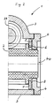
- gear wheel 1 shows a partial cross section through a spindle gear 1, the gear wheel 2 (whose axis lies in the paper plane) being driven by a worm wheel 28 (axis perpendicular to the paper plane).
- Worm wheel 28 and gear wheel 2 are located in a housing 3, which is closed from the side with a housing cover 4, which contains the passage opening 4 a for the spindle shaft, not shown here.
- the inside of the housing cover 4 serves as a contact surface 5 for the axial support via the support disk 7, which serves as an axial sliding bearing on the gear wheel side.
- the play 8 between the contact surface 5 of the housing cover 4 (see also FIG. 2) is clearly visible as a result of the deformations 10 in the contact surface 5 restricted to the play required for sliding, practically written out at 0 in the example shown.
- the deformations 10 shown in FIG. 1 are evenly distributed over the entire circumference of the housing cover 4. Through this uniform support of the support disk 7 is achieved, which in turn transmits the axial bearing forces of the gear wheel 2 to the curvatures of the housing cover 4.
- 5 to 8 show a schematic simplification of the embodiment of the invention in different types of gear and bearings.
- FIG. 5 shows a bevel gear transmission, designated 32 as a whole, the bevel gears 33 and 34 of which are slidably mounted in a housing 3.
- the axial bearing play in the bearings 36 is compensated in the exemplary embodiment by minimal deformations 10 of the contact surface 5 which are not visible in the drawing.
- the press-in points 31 which leave the deformation tool and which, as cannot be seen in the drawing, extend over the circumference of the Contact area of the support plate 7 are distributed.
- Fig. 6 shows a bevel gear according to the invention with roller bearing 36.
- This embodiment makes it clear that the axial play narrowing is not limited to gearboxes with slidingly mounted gearwheels.
- the construction according to the invention saves on the one hand the screwing of the bearing cover 4, on the other hand an otherwise complex expansion of the hard-to-access gear 39 necessary for narrowing the axial play pressed in the area of the contact surface 5 of the gear 39.
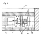
- FIG. 7 shows a partial cross section through a worm gear designated as a whole by 40 as a further exemplary embodiment of the gear according to the invention.
- the gearwheel 41 driven by the worm 42 has slide bearings 43, the axial play of which is compensated for by an axial point bearing 44 by a deformation 10 applied centrally in the axial contact surface 5.
- the press-in point 31 is located centrally in the housing cover 4. The advantage of this embodiment is that a central deformation area 10 and thus also a single press-in point 31 is sufficient to compensate for the axial play 8.
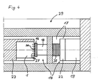
- the worm 45 of a worm gear designated 46 which is suitable for the transmission of large forces, is provided with roller bearings 47, the axial play via the support disk 7 being compensated for by deformations on the circumference of the contact surface 5.
- the minimal deformations 10 which are not visible in the drawing are pressed into the housing cover 4 from the outside, as can be seen at the press-in points 31.
- those housing parts which serve with their inner surface as contact surface 5 for supporting the axial bearing 6 of the gear wheels 2 are made of a cold flowable material, preferably of die-cast zinc, an aluminum alloy, a steel alloy or the like.
- the gears can also consist of plastic gears, because the risk of melting of the plastic, which occurs when hot deformation is otherwise necessary, is avoided.
- the supporting disks used in the illustrated exemplary embodiments expediently consist of a steel alloy, in particular when, as in the exemplary embodiments in FIGS. 1, 2, 5 and 7, they are gears with axial plain bearings and they are also used for Pressure wear of the wear are exposed to friction.
- the axial play compensation can be combined with a compensation or a narrowing of any radial play that is present.
- the press-in points must be close enough to the inner edge of the passage opening 4 a of the gear housing 3, which serves as a radial slide bearing.
- the displacement of the press-in points 31 close to the passage openings 4 a causes a noticeable material deformation or displacement in the radial direction towards the gear wheel. Axial and radial play compensation can thus be carried out in one operation.
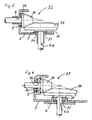
- a deformation device designated as a whole by 29, consists of an abutment 23 and a stamp unit 16.
- the gear 1, 32, 37, 40, 46 or the like clamped so that the housing cover 4 to be deformed or the housing part 3 a to be deformed (with the surface perpendicular to the plane of the drawing) faces the deformation tool of the stamp 14 of the stamp unit 16.
- the deformation tool is moved by a piston 18 which is driven by a working cylinder 19.
- the projections of the shaping tool designed as spikes 27 penetrate into the part of the gear housing 3 a to be deformed until a load cell 22 via the control valves of the working cylinder 19 further feeds of the piston 18 is prevented.
- the force at which it is switched off is determined by the thickness of the housing part to be deformed, by the shape of the projections 27, which are mounted on the disk 26 of the deformation tool and the size of the axial play to be restricted.
- Pronounced deformations 10 are brought about by acute-angled, flat deformations 10 by obtuse-angled projections 27, spikes or the like. Through a suitable choice of the projections, a continuous deformation of the contact surface can also be achieved.
- the projection 27 is designed as an annular wedge.
- Another type of axial play restriction that can be combined with the method described so far is to bend the housing cover 4 or the corresponding housing part 3 a in a funnel shape in the axial direction against the gear wheel towards the passage opening.
- This is expediently achieved by flat projections 27 of the stamp 14, since here the forces necessary for the deformation are very high and thus simultaneously lead to the desired funnel-like deformation of the housing cover 4 or the corresponding housing part 3 a.
- a uniform deformation of the gear to be machined is achieved in that the punch 14 has a disk 26 with a plurality of mandrels 27 arranged very close to one another on a circle.
- the deformation can be carried out cold.
- the axial play can also be compensated for by gearboxes that contain plastic gearwheels, because the risk of melting of the plastic, which can otherwise occur during hot deformation, is avoided from the outset in the case of cold deformation.
- the cold pressing of the deformations 10 also has the advantage that there is no new axial play 8 due to the regression of the temperature-related material expansion.
Landscapes
- Engineering & Computer Science (AREA)
- General Engineering & Computer Science (AREA)
- Mechanical Engineering (AREA)
- General Details Of Gearings (AREA)
- Gears, Cams (AREA)
- Auxiliary Devices For Music (AREA)
- Numerical Control (AREA)
- Switches With Compound Operations (AREA)
- Gear Transmission (AREA)
Applications Claiming Priority (2)
| Application Number | Priority Date | Filing Date | Title |
|---|---|---|---|
| DE3620863 | 1986-06-21 | ||
| DE19863620863 DE3620863A1 (de) | 1986-06-21 | 1986-06-21 | Getriebe mit axialspielausgleich |
Publications (2)
| Publication Number | Publication Date |
|---|---|
| EP0250844A2 true EP0250844A2 (fr) | 1988-01-07 |
| EP0250844A3 EP0250844A3 (fr) | 1988-09-21 |
Family
ID=6303440
Family Applications (1)
| Application Number | Title | Priority Date | Filing Date |
|---|---|---|---|
| EP87107459A Withdrawn EP0250844A3 (fr) | 1986-06-21 | 1987-05-22 | Transmission avec rattrapage du jeu axial |
Country Status (3)
| Country | Link |
|---|---|
| EP (1) | EP0250844A3 (fr) |
| JP (1) | JPS6353363A (fr) |
| DE (1) | DE3620863A1 (fr) |
Cited By (4)
| Publication number | Priority date | Publication date | Assignee | Title |
|---|---|---|---|---|
| US5502882A (en) * | 1993-04-30 | 1996-04-02 | Emerson Electric Co. | 90 degree speed reducer assembly, process, and measuring machine |
| EP0724093A1 (fr) * | 1995-01-26 | 1996-07-31 | Emerson Electric Co. | Dispositif reducteur de vitesse à 90 degrés et machine de mesure |
| US5836076A (en) * | 1996-11-07 | 1998-11-17 | Emerson Electric Co. | Aligning system and machine for a double enveloping speed reducer |
| CN117167445A (zh) * | 2023-09-13 | 2023-12-05 | 江苏马步崎电机制造有限公司 | 一种双输入功率分流差动行星减速机 |
Families Citing this family (3)
| Publication number | Priority date | Publication date | Assignee | Title |
|---|---|---|---|---|
| DE10153441B4 (de) * | 2001-10-30 | 2004-01-29 | Ab Skf | Halteelement zur Festlegung eines Maschinenteils |
| DE102008004604A1 (de) | 2008-01-16 | 2009-07-23 | Daimler Ag | Verfahren zur Bestimmung der Dicke einer Axialausgleichsscheibe |
| DE102015216707B4 (de) * | 2015-06-19 | 2019-09-05 | Adient Luxembourg Holding S.À R.L. | Getriebemotor, Vorrichtung zum Spielfreistellen einer Welle, und Fahrzeugsitz |
Family Cites Families (11)
| Publication number | Priority date | Publication date | Assignee | Title |
|---|---|---|---|---|
| US2108262A (en) * | 1933-11-03 | 1938-02-15 | Dain Mfg Company | Worm and worm gear assembly |
| DE826529C (de) * | 1950-04-14 | 1952-01-03 | Willy Sondergeld | Einrichtung zur genauen Festlegung der gegenseitigen Lage von zwei sich durchdringenden Konstruktionsteilen beim Zusammenbau |
| US2881646A (en) * | 1955-12-23 | 1959-04-14 | Douglas Aircraft Co Inc | Staking tool |
| US2911855A (en) * | 1957-09-30 | 1959-11-10 | Librascope Inc | Bearing spacer |
| JPS5135870Y2 (fr) * | 1973-11-27 | 1976-09-03 | ||
| DE2510171A1 (de) * | 1975-03-08 | 1976-09-16 | Volkswagenwerk Ag | Verschliessen einer oeffnung in einem metallischen werkstueck |
| DE2611218A1 (de) * | 1976-03-17 | 1977-10-06 | Kugelfischer G Schaefer & Co | Form- und kraftschluessige verbindung von waelzlagerteilen mit umgebungsteilen |
| US4214465A (en) * | 1977-11-25 | 1980-07-29 | Temper Corporation | Tolerance compensating deforming press |
| DE3329120A1 (de) * | 1983-08-11 | 1985-02-21 | Siemens AG, 1000 Berlin und 8000 München | Anordnung zur begrenzung des axialspiels einer gleitgelagerten welle eines motorantriebs |
| IT8520421U1 (it) * | 1985-01-08 | 1986-07-08 | Comer Spa | Gruppo di trasmissione cinematica a rinvio angolare, particolarmente per macchine agricole. |
| DE8702420U1 (de) * | 1987-02-17 | 1987-04-09 | Universal-Antriebe GmbH, 7263 Bad Liebenzell | Getriebe |
-
1986
- 1986-06-21 DE DE19863620863 patent/DE3620863A1/de active Granted
-
1987
- 1987-05-22 EP EP87107459A patent/EP0250844A3/fr not_active Withdrawn
- 1987-06-19 JP JP62151565A patent/JPS6353363A/ja active Pending
Cited By (6)
| Publication number | Priority date | Publication date | Assignee | Title |
|---|---|---|---|---|
| US5502882A (en) * | 1993-04-30 | 1996-04-02 | Emerson Electric Co. | 90 degree speed reducer assembly, process, and measuring machine |
| US5590561A (en) * | 1993-04-30 | 1997-01-07 | Emerson Electric Co. | 90 degree speed reducer assembly, process, and measuring machine |
| US5634371A (en) * | 1993-04-30 | 1997-06-03 | Emerson Electric Co. | 90 degree speed reducer assembly, process, and measuring machine |
| EP0724093A1 (fr) * | 1995-01-26 | 1996-07-31 | Emerson Electric Co. | Dispositif reducteur de vitesse à 90 degrés et machine de mesure |
| US5836076A (en) * | 1996-11-07 | 1998-11-17 | Emerson Electric Co. | Aligning system and machine for a double enveloping speed reducer |
| CN117167445A (zh) * | 2023-09-13 | 2023-12-05 | 江苏马步崎电机制造有限公司 | 一种双输入功率分流差动行星减速机 |
Also Published As
| Publication number | Publication date |
|---|---|
| DE3620863A1 (de) | 1987-12-23 |
| JPS6353363A (ja) | 1988-03-07 |
| DE3620863C2 (fr) | 1988-12-29 |
| EP0250844A3 (fr) | 1988-09-21 |
Similar Documents
| Publication | Publication Date | Title |
|---|---|---|
| DE69715113T2 (de) | Synchronring für eine Getriebe-Synchronisiereinrichtung | |
| EP0521843B1 (fr) | Anneau de friction | |
| DE10115783B4 (de) | Gesinterte, mit einem Flansch versehene Riemenscheibe | |
| DE3306312C3 (de) | Bewegliche kupplungs- oder bremsscheibe fuer eine elektromagnetische kupplung oder bremse | |
| DE2817389A1 (de) | Mechanische bremsbetaetigungsvorrichtung | |
| DE69013514T2 (de) | Verfahren zum herstellen von bauelementen einer flüssigkeitskammer. | |
| DE69618149T2 (de) | Schutzflansch für Rollenlager, damit ausgerüstetes Lager und Herstellungsverfahren für einen Lagerring, der mit einem Schutzflansch versehen ist | |
| EP0250844A2 (fr) | Transmission avec rattrapage du jeu axial | |
| DE2607755C2 (fr) | ||
| DE3434463C2 (fr) | ||
| DE3440961C1 (de) | Verfahren zum Herstellen von gehaerteten Laufscheiben fuer Axialwaelzlager | |
| DE19705513C2 (de) | Riemenscheibenvorrichtung eines stufenlos variablen Getriebes und Verfahren zur Herstellung derselben | |
| EP2436456B1 (fr) | Rondelle d'écartement pour transmission et son procédé de fabrication | |
| DE69120634T2 (de) | Verfahren zum Herstellen der Seitenleiste eines zusammengesetzten Ölrings | |
| DE2831142C2 (de) | Durchbiegungseinstellwalze | |
| DE102004024003A1 (de) | Lagerung für eine Antriebsritzelwelle insbesondere eines Allrad-Vorderachsgetriebes | |
| EP2165785B1 (fr) | Dispositif et procédé de fabrication de rainures longitudinales dans des pièces usinées cylindriques | |
| DE19758278B4 (de) | Verfahren und Vorrichtung zur Herstellung einer Tellerfeder mit einer umlaufenden Vertiefung | |
| DE102006053731A1 (de) | Vorrichtung mit einem auf Temperaturwechsel reagierenden Kompensationselement | |
| EP0846236A1 (fr) | Joint d'arbre et son procede de production | |
| DE10328052B4 (de) | Umformwerkzeug, insbesondere Knetwerkzeug | |
| DE2545922A1 (de) | Lagerbuchse fuer dreh- oder schwenklager | |
| DE2758480C3 (de) | Verfahren zur Herstellung von Tagentialspreizfedern für Ölabstreifkolbenringe | |
| DE2929351A1 (de) | Dichtungsanordnung, insbesondere rotierende dichtung | |
| DE102013101695A1 (de) | Kupplungsscheibe und Herstellungsverfahren |
Legal Events
| Date | Code | Title | Description |
|---|---|---|---|
| PUAI | Public reference made under article 153(3) epc to a published international application that has entered the european phase |
Free format text: ORIGINAL CODE: 0009012 |
|
| AK | Designated contracting states |
Kind code of ref document: A2 Designated state(s): AT BE CH DE ES FR GB IT LI LU NL SE |
|
| PUAL | Search report despatched |
Free format text: ORIGINAL CODE: 0009013 |
|
| AK | Designated contracting states |
Kind code of ref document: A3 Designated state(s): AT BE CH DE ES FR GB IT LI LU NL SE |
|
| STAA | Information on the status of an ep patent application or granted ep patent |
Free format text: STATUS: THE APPLICATION IS DEEMED TO BE WITHDRAWN |
|
| 18D | Application deemed to be withdrawn |
Effective date: 19890322 |
|
| RIN1 | Information on inventor provided before grant (corrected) |
Inventor name: KETTERER, THOMAS |