EP0250844A2 - Transmission with axial backlash elimination - Google Patents
Transmission with axial backlash elimination Download PDFInfo
- Publication number
- EP0250844A2 EP0250844A2 EP87107459A EP87107459A EP0250844A2 EP 0250844 A2 EP0250844 A2 EP 0250844A2 EP 87107459 A EP87107459 A EP 87107459A EP 87107459 A EP87107459 A EP 87107459A EP 0250844 A2 EP0250844 A2 EP 0250844A2
- Authority
- EP
- European Patent Office
- Prior art keywords
- housing
- deformation
- contact surface
- axial
- transmission
- Prior art date
- Legal status (The legal status is an assumption and is not a legal conclusion. Google has not performed a legal analysis and makes no representation as to the accuracy of the status listed.)
- Withdrawn
Links
Images


Classifications
-
- F—MECHANICAL ENGINEERING; LIGHTING; HEATING; WEAPONS; BLASTING
- F16—ENGINEERING ELEMENTS AND UNITS; GENERAL MEASURES FOR PRODUCING AND MAINTAINING EFFECTIVE FUNCTIONING OF MACHINES OR INSTALLATIONS; THERMAL INSULATION IN GENERAL
- F16H—GEARING
- F16H1/00—Toothed gearings for conveying rotary motion
- F16H1/02—Toothed gearings for conveying rotary motion without gears having orbital motion
- F16H1/04—Toothed gearings for conveying rotary motion without gears having orbital motion involving only two intermeshing members
- F16H1/12—Toothed gearings for conveying rotary motion without gears having orbital motion involving only two intermeshing members with non-parallel axes
- F16H1/16—Toothed gearings for conveying rotary motion without gears having orbital motion involving only two intermeshing members with non-parallel axes comprising worm and worm-wheel
-
- F—MECHANICAL ENGINEERING; LIGHTING; HEATING; WEAPONS; BLASTING
- F16—ENGINEERING ELEMENTS AND UNITS; GENERAL MEASURES FOR PRODUCING AND MAINTAINING EFFECTIVE FUNCTIONING OF MACHINES OR INSTALLATIONS; THERMAL INSULATION IN GENERAL
- F16C—SHAFTS; FLEXIBLE SHAFTS; ELEMENTS OR CRANKSHAFT MECHANISMS; ROTARY BODIES OTHER THAN GEARING ELEMENTS; BEARINGS
- F16C25/00—Bearings for exclusively rotary movement adjustable for wear or play
-
- F—MECHANICAL ENGINEERING; LIGHTING; HEATING; WEAPONS; BLASTING
- F16—ENGINEERING ELEMENTS AND UNITS; GENERAL MEASURES FOR PRODUCING AND MAINTAINING EFFECTIVE FUNCTIONING OF MACHINES OR INSTALLATIONS; THERMAL INSULATION IN GENERAL
- F16H—GEARING
- F16H1/00—Toothed gearings for conveying rotary motion
- F16H1/02—Toothed gearings for conveying rotary motion without gears having orbital motion
- F16H1/04—Toothed gearings for conveying rotary motion without gears having orbital motion involving only two intermeshing members
- F16H1/12—Toothed gearings for conveying rotary motion without gears having orbital motion involving only two intermeshing members with non-parallel axes
- F16H1/14—Toothed gearings for conveying rotary motion without gears having orbital motion involving only two intermeshing members with non-parallel axes comprising conical gears only
-
- F—MECHANICAL ENGINEERING; LIGHTING; HEATING; WEAPONS; BLASTING
- F16—ENGINEERING ELEMENTS AND UNITS; GENERAL MEASURES FOR PRODUCING AND MAINTAINING EFFECTIVE FUNCTIONING OF MACHINES OR INSTALLATIONS; THERMAL INSULATION IN GENERAL
- F16H—GEARING
- F16H57/00—General details of gearing
- F16H57/12—Arrangements for adjusting or for taking-up backlash not provided for elsewhere
-
- F—MECHANICAL ENGINEERING; LIGHTING; HEATING; WEAPONS; BLASTING
- F16—ENGINEERING ELEMENTS AND UNITS; GENERAL MEASURES FOR PRODUCING AND MAINTAINING EFFECTIVE FUNCTIONING OF MACHINES OR INSTALLATIONS; THERMAL INSULATION IN GENERAL
- F16C—SHAFTS; FLEXIBLE SHAFTS; ELEMENTS OR CRANKSHAFT MECHANISMS; ROTARY BODIES OTHER THAN GEARING ELEMENTS; BEARINGS
- F16C2361/00—Apparatus or articles in engineering in general
- F16C2361/61—Toothed gear systems, e.g. support of pinion shafts
-
- F—MECHANICAL ENGINEERING; LIGHTING; HEATING; WEAPONS; BLASTING
- F16—ENGINEERING ELEMENTS AND UNITS; GENERAL MEASURES FOR PRODUCING AND MAINTAINING EFFECTIVE FUNCTIONING OF MACHINES OR INSTALLATIONS; THERMAL INSULATION IN GENERAL
- F16H—GEARING
- F16H57/00—General details of gearing
- F16H57/02—Gearboxes; Mounting gearing therein
- F16H57/021—Shaft support structures, e.g. partition walls, bearing eyes, casing walls or covers with bearings
- F16H2057/0213—Support of worm gear shafts
-
- F—MECHANICAL ENGINEERING; LIGHTING; HEATING; WEAPONS; BLASTING
- F16—ENGINEERING ELEMENTS AND UNITS; GENERAL MEASURES FOR PRODUCING AND MAINTAINING EFFECTIVE FUNCTIONING OF MACHINES OR INSTALLATIONS; THERMAL INSULATION IN GENERAL
- F16H—GEARING
- F16H57/00—General details of gearing
- F16H57/02—Gearboxes; Mounting gearing therein
- F16H57/021—Shaft support structures, e.g. partition walls, bearing eyes, casing walls or covers with bearings
- F16H57/022—Adjustment of gear shafts or bearings
- F16H2057/0221—Axial adjustment
-
- F—MECHANICAL ENGINEERING; LIGHTING; HEATING; WEAPONS; BLASTING
- F16—ENGINEERING ELEMENTS AND UNITS; GENERAL MEASURES FOR PRODUCING AND MAINTAINING EFFECTIVE FUNCTIONING OF MACHINES OR INSTALLATIONS; THERMAL INSULATION IN GENERAL
- F16H—GEARING
- F16H57/00—General details of gearing
- F16H57/12—Arrangements for adjusting or for taking-up backlash not provided for elsewhere
- F16H2057/125—Adjustment of backlash during mounting or assembly of gearing
-
- F—MECHANICAL ENGINEERING; LIGHTING; HEATING; WEAPONS; BLASTING
- F16—ENGINEERING ELEMENTS AND UNITS; GENERAL MEASURES FOR PRODUCING AND MAINTAINING EFFECTIVE FUNCTIONING OF MACHINES OR INSTALLATIONS; THERMAL INSULATION IN GENERAL
- F16H—GEARING
- F16H55/00—Elements with teeth or friction surfaces for conveying motion; Worms, pulleys or sheaves for gearing mechanisms
- F16H55/02—Toothed members; Worms
- F16H55/22—Toothed members; Worms for transmissions with crossing shafts, especially worms, worm-gears
- F16H55/24—Special devices for taking up backlash
Definitions
- the invention relates to a transmission with at least one gear wheel, which has an axial bearing and an axially acting, in the housing or on the inside of a housing cover made of metal and has a support between the contact surface and the gear wheel, and an axial play compensation is provided between the support and the contact surface is.
- Such gears are known in a wide variety of designs. Especially in spindle motor gears, where very strong reductions are generated and the nut should be fixed in the axial direction, whereby comparatively high forces have to be transmitted, it can be important that the nut is mounted in the manner mentioned at the outset without axial play but still rotatable. Since the production can usually not be carried out so precisely that there is no play in the axial direction from the outset, the play must be subsequently made during assembly by additional shims between the contact surface of the gear cover and the support plate. Under certain circumstances, this may involve opening and closing the gear cover several times, so that the axial play compensation considerably increases the time required for assembly. this is also valid then when the axial support of the corresponding gear wheel, in the aforementioned example the spindle nut, is formed directly by the contact surface of the gear housing or cover.
- the solution to the problem is that cold-formed, against the gear wheel, distributed over the circumference deformations in the bearing surface of the housing or the housing cover are provided as axial play compensation or constriction after assembly of the transmission.
- the main advantage of the transmission according to the invention is that the labor and thus the cost of manufacture are significantly lower than the manufacture of the known transmission. This is primarily due to the fact that the axial play after installation can be compensated for with the housing closed. This saves the work of screwing on the housing cover or, as in some cases, further removing the gear wheel and makes the tedious process of trying out spacers or the like unnecessary.
- the pressed-in curvatures take over the axial clearance-restricting function with the same certainty as the previously used spacers or the like.
- a uniform narrowing of the axial play is achieved in particular in that the cold-formed projections are evenly distributed around the circumference and / or are formed as a uniformly circumferential bead and / or that in the area of a transmission outlet the edge area as a whole, for. B. is shaped like a funnel inwards.
- the housing part having the contact surface is made of a cold-flowable material, in particular metal, preferably die-cast zinc , an aluminum alloy, a steel alloy or the like.
- the deformation process is also facilitated if the area of the contact surface to be deformed preferably has a reduced wall thickness compared to the rest of the gear housing. As with the choice of material (see above), this also reduces the risk that the housing will be overloaded by the deformation process and thereby deformed.
- a support disk is arranged between the contact surface of the gear housing or cover and the gear wheel, which is preferably made of hardened Steel.
- an additional radial play compensation after assembly of the transmission is possible for transmissions in which a passage opening through the transmission housing or the housing cover serves as the radial bearing of the transmission wheel.
- a passage opening through the transmission housing or the housing cover serves as the radial bearing of the transmission wheel.
- the invention also relates to a method for producing the above-described gear, in particular for narrowing the axial play of at least one gear.
- This method is particularly characterized in that after assembly of the transmission, the contact surface for the gear wheel or for a support disk located between the gear wheel and the contact surface is deformed from the outside inwards with a limited force - below the force causing an axial deformation of the gear wheel is that the originally existing axial play is narrowed.
- the advantages of this method lie in the reduction of the work involved in narrowing the axial play of gear wheels. There is no need to screw on the gearbox and insert spacer rings or washers. Since the force during the material deformation is limited, there is no danger that the gear wheel and / or the housing will be deformed by the deformation process.
- the method can also be used for narrowing the axial play of plastic gearwheels because the risk of melting of the plastic, as occurs with hot deformation, is avoided.
- all the deformations are expediently pressed into the housing cover or into the housing at the same time.
- the deformations can preferably, depending on the extent of the radial curvature required, close to the circumference of the radial bearing in the housing cover or be pressed into the housing.
- the method is based on the fact that the pressing process carried out in the axial direction on the material of the housing cover or the housing causes the displacement pressure or material displacement not only in the axial direction but also to a small extent in the radial direction. A noticeable deformation in the radial direction only occurs when the pressing points are close enough to the inner edge of the passage opening.
- the invention also relates to a device for carrying out the method described above.
- This device consists of an abutment for clamping or holding the gearbox and a stamp unit with a movable stamp which is moved by a working cylinder or a spindle motor or the like.
- the stamp is designed as a deformation tool and a force limiter is provided in the stamp unit is, which automatically prevents further advancement of the punch via a control loop when the predetermined highest deformation is reached.
- the device thus allows to automatically limit the force for controlled deformation of the housing cover or the housing.
- a working cylinder can be used, which is provided with a piston, and as a force limiter, a load cell for automatically actuating the working cylinder can be attached, which automatically prevents further advance of the punch when the predetermined highest deformation force is reached.
- the stamp serving as the deformation tool has a disc, preferably with projections arranged on a circle, in particular spikes or the like, which are formed at an acute angle to achieve pronounced deformation or at an obtuse angle to achieve a flat deformation.
- the shape of the deformations of the contact surface can thus also be influenced by the choice of the shape of the projections. If the projections are formed, for example, as pointed thorns at a large distance from one another, individual curvatures form in the contact surface. If the disc has flat curvatures, the pressure required for deformation on the housing cover or the housing is increased. As a result, in addition to a flat curvature of the contact surface, the housing cover or the housing can be bent inwards in a funnel-like manner around the passage opening, as a result of which the axial play is also narrowed.
- the projections arranged in a circle on the disk can also be designed as a circular wedge, which can bring about a uniform deformation of the contact surface or a funnel-like bending of the housing cover or the corresponding housing part towards the passage opening.
- the shape of the projections can also vary the force required for the deformation. The pressure required on the housing cover or on the housing part to be deformed is lower, the more acute the projections are and the smaller the surface, which is defined by the edge of the press-in points, is the surface of the housing cover or the housing part to be deformed That is, which is pressed in by the projections, thorns or the like.
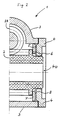
- gear wheel 1 shows a partial cross section through a spindle gear 1, the gear wheel 2 (whose axis lies in the paper plane) being driven by a worm wheel 28 (axis perpendicular to the paper plane).
- Worm wheel 28 and gear wheel 2 are located in a housing 3, which is closed from the side with a housing cover 4, which contains the passage opening 4 a for the spindle shaft, not shown here.
- the inside of the housing cover 4 serves as a contact surface 5 for the axial support via the support disk 7, which serves as an axial sliding bearing on the gear wheel side.
- the play 8 between the contact surface 5 of the housing cover 4 (see also FIG. 2) is clearly visible as a result of the deformations 10 in the contact surface 5 restricted to the play required for sliding, practically written out at 0 in the example shown.
- the deformations 10 shown in FIG. 1 are evenly distributed over the entire circumference of the housing cover 4. Through this uniform support of the support disk 7 is achieved, which in turn transmits the axial bearing forces of the gear wheel 2 to the curvatures of the housing cover 4.
- 5 to 8 show a schematic simplification of the embodiment of the invention in different types of gear and bearings.
- FIG. 5 shows a bevel gear transmission, designated 32 as a whole, the bevel gears 33 and 34 of which are slidably mounted in a housing 3.
- the axial bearing play in the bearings 36 is compensated in the exemplary embodiment by minimal deformations 10 of the contact surface 5 which are not visible in the drawing.
- the press-in points 31 which leave the deformation tool and which, as cannot be seen in the drawing, extend over the circumference of the Contact area of the support plate 7 are distributed.
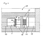
- Fig. 6 shows a bevel gear according to the invention with roller bearing 36.
- This embodiment makes it clear that the axial play narrowing is not limited to gearboxes with slidingly mounted gearwheels.
- the construction according to the invention saves on the one hand the screwing of the bearing cover 4, on the other hand an otherwise complex expansion of the hard-to-access gear 39 necessary for narrowing the axial play pressed in the area of the contact surface 5 of the gear 39.
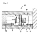
- FIG. 7 shows a partial cross section through a worm gear designated as a whole by 40 as a further exemplary embodiment of the gear according to the invention.
- the gearwheel 41 driven by the worm 42 has slide bearings 43, the axial play of which is compensated for by an axial point bearing 44 by a deformation 10 applied centrally in the axial contact surface 5.
- the press-in point 31 is located centrally in the housing cover 4. The advantage of this embodiment is that a central deformation area 10 and thus also a single press-in point 31 is sufficient to compensate for the axial play 8.
- the worm 45 of a worm gear designated 46 which is suitable for the transmission of large forces, is provided with roller bearings 47, the axial play via the support disk 7 being compensated for by deformations on the circumference of the contact surface 5.
- the minimal deformations 10 which are not visible in the drawing are pressed into the housing cover 4 from the outside, as can be seen at the press-in points 31.
- those housing parts which serve with their inner surface as contact surface 5 for supporting the axial bearing 6 of the gear wheels 2 are made of a cold flowable material, preferably of die-cast zinc, an aluminum alloy, a steel alloy or the like.
- the gears can also consist of plastic gears, because the risk of melting of the plastic, which occurs when hot deformation is otherwise necessary, is avoided.
- the supporting disks used in the illustrated exemplary embodiments expediently consist of a steel alloy, in particular when, as in the exemplary embodiments in FIGS. 1, 2, 5 and 7, they are gears with axial plain bearings and they are also used for Pressure wear of the wear are exposed to friction.
- the axial play compensation can be combined with a compensation or a narrowing of any radial play that is present.
- the press-in points must be close enough to the inner edge of the passage opening 4 a of the gear housing 3, which serves as a radial slide bearing.
- the displacement of the press-in points 31 close to the passage openings 4 a causes a noticeable material deformation or displacement in the radial direction towards the gear wheel. Axial and radial play compensation can thus be carried out in one operation.
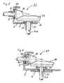
- a deformation device designated as a whole by 29, consists of an abutment 23 and a stamp unit 16.
- the gear 1, 32, 37, 40, 46 or the like clamped so that the housing cover 4 to be deformed or the housing part 3 a to be deformed (with the surface perpendicular to the plane of the drawing) faces the deformation tool of the stamp 14 of the stamp unit 16.
- the deformation tool is moved by a piston 18 which is driven by a working cylinder 19.
- the projections of the shaping tool designed as spikes 27 penetrate into the part of the gear housing 3 a to be deformed until a load cell 22 via the control valves of the working cylinder 19 further feeds of the piston 18 is prevented.
- the force at which it is switched off is determined by the thickness of the housing part to be deformed, by the shape of the projections 27, which are mounted on the disk 26 of the deformation tool and the size of the axial play to be restricted.
- Pronounced deformations 10 are brought about by acute-angled, flat deformations 10 by obtuse-angled projections 27, spikes or the like. Through a suitable choice of the projections, a continuous deformation of the contact surface can also be achieved.
- the projection 27 is designed as an annular wedge.
- Another type of axial play restriction that can be combined with the method described so far is to bend the housing cover 4 or the corresponding housing part 3 a in a funnel shape in the axial direction against the gear wheel towards the passage opening.
- This is expediently achieved by flat projections 27 of the stamp 14, since here the forces necessary for the deformation are very high and thus simultaneously lead to the desired funnel-like deformation of the housing cover 4 or the corresponding housing part 3 a.
- a uniform deformation of the gear to be machined is achieved in that the punch 14 has a disk 26 with a plurality of mandrels 27 arranged very close to one another on a circle.
- the deformation can be carried out cold.
- the axial play can also be compensated for by gearboxes that contain plastic gearwheels, because the risk of melting of the plastic, which can otherwise occur during hot deformation, is avoided from the outset in the case of cold deformation.
- the cold pressing of the deformations 10 also has the advantage that there is no new axial play 8 due to the regression of the temperature-related material expansion.
Abstract
Description
Die Erfindung betrifft ein Getriebe mit wenigstens einem Getrieberad, welches eine axiale Lagerung und eine axial wirkende, im Gehäuse oder an der Innenseite eines aus Metall bestehenden Gehäusedeckels befindliche Anlagefläche aufweist und zwischen Anlagefläche und dem Getrieberad eine Abstützung vorhanden sowie zwischen Abstützung und Anlagefläche ein Axialspielausgleich vorgesehen ist.The invention relates to a transmission with at least one gear wheel, which has an axial bearing and an axially acting, in the housing or on the inside of a housing cover made of metal and has a support between the contact surface and the gear wheel, and an axial play compensation is provided between the support and the contact surface is.
Derartige Getriebe sind in unterschiedlichster Ausführung bekannt. Vor allem bei Spindelmotorgetrieben, wo sehr starke Untersetzungen erzeugt werden und die Mutter in axialer Richtung feststehen soll, wobei vergleichsweise hohe Kräfte zu übertragen sind, kann es wichtig sein, daß die Mutter axialspielfrei aber dennoch drehbar in der eingangs erwähnten Art gelagert ist. Da die Fertigung in aller Regel nicht so genau durchgeführt werden kann, daß in axialer Richtung von vorneherein Spielfreiheit besteht, muß die Spielfreiheit bei der Montage nachträglich durch zusätzliche Ausgleichsscheiben in der Regel zwischen Anlagefläche des Getriebedeckels und Abstützscheibe hergestellt werden. Dies kann unter Umständen ein mehrfaches Öffnen und Schließen des Getriebedeckels beinhalten, so daß der Axialspielausgleich den Zeitaufwand bei der Montage erheblich vergrößert. Dies gilt auch dann, wenn die axiale Abstützung des entsprechenden Getrieberades, beim vorerwähnten Beispiel die Spindelmutter, direkt von der Anlagefläche des Getriebegehäuses oder Deckels gebildet ist.Such gears are known in a wide variety of designs. Especially in spindle motor gears, where very strong reductions are generated and the nut should be fixed in the axial direction, whereby comparatively high forces have to be transmitted, it can be important that the nut is mounted in the manner mentioned at the outset without axial play but still rotatable. Since the production can usually not be carried out so precisely that there is no play in the axial direction from the outset, the play must be subsequently made during assembly by additional shims between the contact surface of the gear cover and the support plate. Under certain circumstances, this may involve opening and closing the gear cover several times, so that the axial play compensation considerably increases the time required for assembly. this is also valid then when the axial support of the corresponding gear wheel, in the aforementioned example the spindle nut, is formed directly by the contact surface of the gear housing or cover.
Es besteht deshalb die Aufgabe, ein Getriebe der eingangs erwähnten Art zu schaffen, bei welchem der Axialspielausgleich bei der Montage wesentlich schneller und somit kostensparend durchführbar ist.There is therefore the task of creating a transmission of the type mentioned at the outset, in which the axial play compensation during assembly can be carried out much more quickly and thus in a cost-saving manner.
Die Lösung der Aufgabe besteht darin, daß als Axialspielausgleich bzw. -einengung nach der Montage des Getriebes kalt angeformte, gegen das Getrieberad gerichtete, über den Umfang verteilte Verformungen in der Anlagefläche des Gehäuses bzw. des Gehäusedeckels vorgesehen sind.The solution to the problem is that cold-formed, against the gear wheel, distributed over the circumference deformations in the bearing surface of the housing or the housing cover are provided as axial play compensation or constriction after assembly of the transmission.
Der wesentliche Vorteil des erfindungsgemäßen Getriebes liegt darin, daß der Arbeitsaufwand und damit die Kosten der Herstellung wesentlich geringer sind als die Herstellung der bekannten Getriebe. Dies ist in erster Linie darauf zurückzuführen, daß das Axialspiel nach der Montage bei geschlossenem Gehäuse ausgeglichen werden kann. Dies erspart die Arbeiten des Aufschraubens des Gehäusedeckels oder, wie in manchen Fällen, darüberhinaus das Ausbauen des Getrieberades, und macht den langwierigen Prozeß des Ausprobierens von Distanzscheiben o. ä. unnötig. Die eingepreßten Verwölbungen übernehmen mit gleicher Sicherheit die Axialspiel-einengende Funktion wie die bisher üblichen Distanzscheiben o. ä. .The main advantage of the transmission according to the invention is that the labor and thus the cost of manufacture are significantly lower than the manufacture of the known transmission. This is primarily due to the fact that the axial play after installation can be compensated for with the housing closed. This saves the work of screwing on the housing cover or, as in some cases, further removing the gear wheel and makes the tedious process of trying out spacers or the like unnecessary. The pressed-in curvatures take over the axial clearance-restricting function with the same certainty as the previously used spacers or the like.
Eine gleichmäßige Einengung des Axialspieles wird insbesondere dadurch erreicht, daß die kalt ausgeformten Vorsprünge gleichmäßig am Umfang verteilt sind und/oder als gleichmäßig umlaufende Wulst ausgebildet sind und/oder daß im Bereich eines Getriebeaustrittes der Randbereich insgesamt z. B. trichterartig nach innen verformt ist.A uniform narrowing of the axial play is achieved in particular in that the cold-formed projections are evenly distributed around the circumference and / or are formed as a uniformly circumferential bead and / or that in the area of a transmission outlet the edge area as a whole, for. B. is shaped like a funnel inwards.
Um das Getriebegehäuse durch die Kaltverformung nicht zu verziehen und um eine gleichmäßige Verformung der Anlagefläche mit einem "weichen" Preßvorgang zu erreichen, ist es zweckmäßig, wenn der die Anlagefläche aufweisende Gehäuseteil aus einem kalt fließfähigen Werkstoff, insbesondere Metall, vorzugsweise Zink-Druck-Guß, einer Aluminiumlegierung, einer Stahllegierung od. dgl. besteht. Der Verformungsvorgang wird darüberhinaus dann erleichtert, wenn der zu verformende Bereich der Anlagefläche gegenüber dem übrigen Getriebegehäuse vorzugsweise eine verringerte Wandstärke hat. Hierdurch wird auch, wie schon durch die Wahl des Werkstoffes (siehe oben), die Gefahr vermindert, daß das Gehäuse durch den Verformungsvorgang überlastet und dadurch verformt wird.In order not to warp the gear housing due to the cold deformation and to achieve a uniform deformation of the contact surface with a "soft" pressing process, it is expedient if the housing part having the contact surface is made of a cold-flowable material, in particular metal, preferably die-cast zinc , an aluminum alloy, a steel alloy or the like. The deformation process is also facilitated if the area of the contact surface to be deformed preferably has a reduced wall thickness compared to the rest of the gear housing. As with the choice of material (see above), this also reduces the risk that the housing will be overloaded by the deformation process and thereby deformed.
Unabhängig davon, ob die axiale Lagerung des Getrieberades, dessen Spiel einzuengen ist, aus einem Gleit- oder Wälzlager besteht, erweist es sich als vorteilhaft, daß zwischen der Anlagefläche des Getriebegehäuses oder-deckels und dem Getrieberad eine Abstützscheibe angeordnet ist, die vorzugsweise aus gehärtetem Stahl besteht. Durch diese Ausgleichsscheibe werden die axialen Lagerkräfte gleichmäßig aufgefangen, ohne daß es durch die distanzverringernden Verwölbungen auf der Innenseite des Getriebedeckels zu punktuell erhöhtem Druck auf das Getrieberad bzw. die Stellen der Verwölbung kommt. Die Anlauffläche bleibt glatt, woduch einer erhöhten Reibung an den Stellen der Verwölbung und damit einem erhöhten Verschleiß der Lagerflächen vorgebeugt wird.Regardless of whether the axial bearing of the gear wheel, the play of which is to be narrowed, consists of a sliding or rolling bearing, it proves to be advantageous that a support disk is arranged between the contact surface of the gear housing or cover and the gear wheel, which is preferably made of hardened Steel. With this shim, the axial bearing forces are absorbed evenly, without there being occasionally increased pressure on the gear wheel or the points of the warping due to the distance-reducing warpage on the inside of the transmission cover. The contact surface remains smooth, which prevents increased friction at the points of the warping and thus increased wear on the bearing surfaces.
In einer weiteren Ausgestaltung der Erfindung ist für Getriebe, in welchem eine Durchtrittsöffnung durch das Getriebegehäuse bzw. dem Gehäusedeckel als radiale Lagerung des Getrieberades dient, ein zusätzlicher Radialspielausgleich nach der Montage des Getriebes möglich. Dazu kann an der Seite des Getrieberades, an dem die Verwölbungen zur Axialspieleinengung vorgesehen sind, der Innenrand der Durchtrittsöffnung über den Umfang in radialer Richtung gegen das Getriebe kalt verformt sein.In a further embodiment of the invention, an additional radial play compensation after assembly of the transmission is possible for transmissions in which a passage opening through the transmission housing or the housing cover serves as the radial bearing of the transmission wheel. For this purpose, on the side of the gear wheel on which the curvatures for narrowing the axial play are provided, the inner edge of the passage opening can be cold deformed over the circumference in the radial direction against the gear.
Die Erfindung betrifft auch ein Verfahren zur Herstellung des vorbeschriebenen Getriebes, insbesondere zur Einengung des Axialspieles wenigstens eines Getrieberades. Dieses Verfahren ist insbesondere dadurch gekennzeichnet, daß nach dem Zusammenbau des Getriebes die Anlagefläche für das Getrieberad oder für eine zwischen Getrieberad und der Anlagefläche befindliche Abstützscheibe von außen her nach innen mit einer begrenzten Kraft - unterhalb der ein axiales Verformen des Getrieberades bewirkenden Kraft -so verformt wird, daß das ursprünglich vorhandene Axialspiel eingeengt wird. Die Vorteile dieses Verfahrens liegen in der Reduzierung des Arbeitsaufwandes zur Einengung des Axialspieles von Getrieberädern. Das nachträgliche Aufschrauben des Getriebes und Einlegen von Distanzringen oder -scheiben entfällt. Da die Kraft bei der Materialverformung begrenzt ist, besteht keine Gefahr, daß durch den Verformungsprozeß das Getrieberad und/oder das Gehäuse verformt werden.The invention also relates to a method for producing the above-described gear, in particular for narrowing the axial play of at least one gear. This method is particularly characterized in that after assembly of the transmission, the contact surface for the gear wheel or for a support disk located between the gear wheel and the contact surface is deformed from the outside inwards with a limited force - below the force causing an axial deformation of the gear wheel is that the originally existing axial play is narrowed. The advantages of this method lie in the reduction of the work involved in narrowing the axial play of gear wheels. There is no need to screw on the gearbox and insert spacer rings or washers. Since the force during the material deformation is limited, there is no danger that the gear wheel and / or the housing will be deformed by the deformation process.
Da die Verformungen kalt in den Gehäusedeckel bzw. in das Gehäuse eingepreßt werden, ist das Verfahren auch zur Axialspieleinengung von Kunststoffgetrieberädern anwendbar, weil die Gefahr des Schmelzens des Kunststoffes, wie sie bei heißer Verformung auftritt, vermieden wird.Since the deformations are pressed cold into the housing cover or into the housing, the method can also be used for narrowing the axial play of plastic gearwheels because the risk of melting of the plastic, as occurs with hot deformation, is avoided.
Um die Bearbeitungszeit für die Einengung bzw. den Ausgleich des Axialspieles klein zu halten und um die Gleichmäßigkeit der Verformungen zu erzielen, werden zweckmäßigerweise alle Verformungen gleichzeitig in dem Gehäusedeckel bzw. in das Gehäuse eingepreßt.In order to keep the processing time for the narrowing or compensation of the axial play small and to achieve the uniformity of the deformations, all the deformations are expediently pressed into the housing cover or into the housing at the same time.
Zur Erreichung eines kombinierten Axial- und Radialspielausgleiches von Getrieben, in welchen eine Durchtrittsöffnung durch den Gehäusedeckel als radiale Lagerung des Getrieberades ausgebildet ist, können die Verformungen vorzugsweise, dem Ausmaß der erforderlichen radialen Verwölbung entsprechend, nahe dem Umfang der radialen Lagerung in den Gehäusedeckel bzw. in das Gehäuse eingepreßt werden. Das Verfahren beruht in dieser Ausgestaltung darauf, daß durch den in axialer Richtung durchgeführten Preßvorgang auf das Material des Gehäusedeckels bzw. des Gehäuses der bewirkte Verschiebungsdruck bzw. die Materialverdrängung nicht nur in axialer, sondern zu einem geringen Teil auch in radialer Richtung erfolgt. Eine merkbare Verformung in radialer Richtung entsteht aber nur dann, wenn die Preßstellen nahe genug am Innenrand der Durchtrittsöffnung liegen. Somit ist es möglich, durch die Variation des Abstandes der Preßstellen vom inneren Rand der Durchtrittsöffnung bzw. der radialen Lagerung des Getrieberades gleichzeitig mit der Einengung des Axialspiels im selben Arbeitsgang auch ein etwa vorhandenes Radialspiel auszugleichen. Für diesen Fall ergibt sich somit eine weitere Steigerung der Effizienz des vorbeschriebenen Verfahrens.To achieve a combined axial and radial play compensation of gearboxes in which a passage opening through the housing cover is designed as a radial bearing for the gearwheel, the deformations can preferably, depending on the extent of the radial curvature required, close to the circumference of the radial bearing in the housing cover or be pressed into the housing. In this embodiment, the method is based on the fact that the pressing process carried out in the axial direction on the material of the housing cover or the housing causes the displacement pressure or material displacement not only in the axial direction but also to a small extent in the radial direction. A noticeable deformation in the radial direction only occurs when the pressing points are close enough to the inner edge of the passage opening. It is thus possible, by varying the distance of the pressing points from the inner edge of the passage opening or the radial mounting of the gear wheel, to compensate for any radial play which may be present in the same operation, with the narrowing of the axial play. In this case there is a further increase in the efficiency of the method described above.
Die Erfindung betrifft auch eine Vorrichtung zur Durchführung des vorbeschriebenen Verfahrens. Diese Vorrichtung besteht aus einem Widerlager zum Einspannen bzw. Halten des Getriebes sowie aus einer Stempeleinheit mit einem bewegbaren Stempel, der von einem Arbeitszylinder oder einem Spindelmotor od. dgl. bewegt wird, wobei der Stempel als Verformungswerkzeug ausgebildet ist und in der Stempeleinheit ein Kraftbegrenzer vorgesehen ist, der über einen Regelkreis beim Erreichen der vorbestimmten höchsten Verformung selbsttätig den weiteren Vorschub des Stempels unterbindet. Die Vorrichtung erlaubt es somit, die Begrenzung der Kraft zur kontrollierten Verformung des Gehäusedeckels bzw. des Gehäuses automatisch vorzunehmen.The invention also relates to a device for carrying out the method described above. This device consists of an abutment for clamping or holding the gearbox and a stamp unit with a movable stamp which is moved by a working cylinder or a spindle motor or the like. The stamp is designed as a deformation tool and a force limiter is provided in the stamp unit is, which automatically prevents further advancement of the punch via a control loop when the predetermined highest deformation is reached. The device thus allows to automatically limit the force for controlled deformation of the housing cover or the housing.
Damit ergibt sich auch die Möglichkeit, den gesamten Vorgang der Axialspieleinengung zu automatisieren, nämlich dann, wenn das Einspannen und Entfernen des Getriebes aus dem Widerlager mechanisiert wird. Diese Möglichkeit bestand bei dem auf Handarbeit beruhenden Axialspielausgleich durch das Ausprobieren verschiedener Distanzscheiben nicht. Durch die automatische Einhaltung der wirkenden Verformungskräfte wird auch eine Beschädigung des Getriebes durch zu hohen Preßdruck vermieden.This also results in the possibility of automating the entire process of narrowing the axial play, namely when the clamping and removal of the transmission from the abutment is mechanized. This was not possible with the axial play compensation based on manual work by trying out different spacers. By automatically maintaining the effective deformation forces, damage to the gearbox due to excessive pressure is avoided.
Als Stempelantrieb kann ein Arbeitszylinder verwandt werden, der mit einem Kolben versehen ist, und als Kraftbegrenzer kann eine Kraftmeßdose zur automatischen Ansteuerung des Arbeitszylinders angebracht sein, die beim Erreichen der vorbestimmten höchsten Verformungskraft selbsttätig den weiteren Vorschub des Stempels unterbindet.As a punch drive, a working cylinder can be used, which is provided with a piston, and as a force limiter, a load cell for automatically actuating the working cylinder can be attached, which automatically prevents further advance of the punch when the predetermined highest deformation force is reached.
Der als Verformungswerkzeug dienende Stempel weist in einer Ausgestaltung der erfindungsgemäßen Vorrichtung eine Scheibe mit vorzugsweise auf einem Kreis angeordneten Vorsprüngen, insbesondere Dornen od. dgl. auf, die zur Erreichung ausgeprägter Verformung spitzwinklig oder zur Erreichung einer flachen Verformung stumpfwinklig ausgebildet sind.In an embodiment of the device according to the invention, the stamp serving as the deformation tool has a disc, preferably with projections arranged on a circle, in particular spikes or the like, which are formed at an acute angle to achieve pronounced deformation or at an obtuse angle to achieve a flat deformation.
Durch die Wahl der Form der Vorsprünge kann somit auch die Gestalt der Verformungen der Anlagefläche beeinflußt werden. Sind die Vorsprünge beispielsweise als spitze Dornen mit großem Abstand voneinander ausgebildet, bilden sich in der Anlagefläche einzelne Verwölbungen aus. Weist die Scheibe flache Verwölbungen auf, so wird der zum Verformen notwendige Druck auf den Gehäusedeckel bzw. das Gehäuse erhöht. Hierdurch kann neben einer flachen Verwölbung der Anlagefläche der Gehäusedeckel bzw. das Gehäuse um die Durchtrittsöffnung herum trichterartig nach innen verbogen werden, wodurch das Axialspiel gleichfalls eingeengt wird. Die auf der Scheibe kreisförmig angeordneten Vorsprünge können auch als kreisförmiger Keil ausgestaltet sein, der eine gleichmäßige Verformung der Anlagefläche bzw. eine trichterartige Verbiegung des Gehäusedeckels bzw. des entsprechenden Gehäuseteiles zur Durchtrittsöffnung hin bewirken kann. Durch die Form der Vorsprünge kann zudem die zur Verformung benötigte Kraft variiert werden. Dabei ist der jeweils erforderliche Druck auf den Gehäusedeckel bzw. auf das zu verformende Gehäuseteil umso geringer, je spitzwinkliger die Vorsprünge sind und je kleiner die Oberfläche ist, die durch den Rand der Einpreßstellen festgelegt ist, derjenigen Oberfläche des Gehäusedeckels bzw. des zu verformenden Gehäuseteiles also, die von den Vorsprüngen, Dornen od. dgl. eingedrückt wird.The shape of the deformations of the contact surface can thus also be influenced by the choice of the shape of the projections. If the projections are formed, for example, as pointed thorns at a large distance from one another, individual curvatures form in the contact surface. If the disc has flat curvatures, the pressure required for deformation on the housing cover or the housing is increased. As a result, in addition to a flat curvature of the contact surface, the housing cover or the housing can be bent inwards in a funnel-like manner around the passage opening, as a result of which the axial play is also narrowed. The projections arranged in a circle on the disk can also be designed as a circular wedge, which can bring about a uniform deformation of the contact surface or a funnel-like bending of the housing cover or the corresponding housing part towards the passage opening. The shape of the projections can also vary the force required for the deformation. The pressure required on the housing cover or on the housing part to be deformed is lower, the more acute the projections are and the smaller the surface, which is defined by the edge of the press-in points, is the surface of the housing cover or the housing part to be deformed That is, which is pressed in by the projections, thorns or the like.
Nachstehend ist die Erfindung mit ihren ihr als wesentlich zugehörigen Einzelheiten anhand der Zeichnungen noch näher beschrieben.The invention is described in more detail below with its details that are essential to it, using the drawings.
Es zeigt :
- Fig. 1 einen Teilquerschnitt durch ein Spindelgetriebe mit Axialspielausgleich,
- Fig. 2 einen Teilquerschnitt durch ein Spindelgetriebe gemäß Fig. 1 vor dem Axialspielausgleich,
- Fig. 3 einen Längsschnitt durch eine Verformungsvorrichtung mit eingespanntem Getriebe in Ausgangsstellung,
- Fig. 4 einen Längsschnitt durch eine Verformungsvorrichtung gemäß Fig. 3 mit eingespanntem Getriebe in Arbeitsstellung,
- Fig. 5 einen Längsschnitt durch ein Kegelradgetriebe mit Gleitlagerung und Axialspielausgleich,
- Fig. 6 einen Längsschnitt durch ein Kegelradgetriebe mit Wälzlagerung und Axialspielausgleich,
- Fig. 7 Teilquerschnitt durch ein Schneckengetriebe mit Gleitlagerung und Axialspielausgleich,
- Fig. 8 einen Teilquerschnitt durch ein Schneckengetriebe mit Wälzlagerung und Axialspielausgleich.
- 1 is a partial cross section through a spindle gear with axial play compensation,
- 2 shows a partial cross section through a spindle gear according to FIG. 1 before the axial play compensation,
- 3 shows a longitudinal section through a deformation device with a clamped gear in the starting position,
- 4 shows a longitudinal section through a deformation device according to FIG. 3 with the transmission clamped in the working position,
- 5 shows a longitudinal section through a bevel gear with slide bearing and axial play compensation,
- 6 shows a longitudinal section through a bevel gear with roller bearings and axial play compensation,
- 7 partial cross section through a worm gear with slide bearing and axial play compensation,
- Fig. 8 is a partial cross section through a worm gear with roller bearings and axial play compensation.
Fig. 1 zeigt einen Teilquerschnitt durch ein Spindelgetriebe 1, wobei das Getrieberad 2 (deren Achse in der Papierebene liegt) von einem Schneckenrad 28 (Achse senkrecht zur Papierebene) angetrieben wird. Schneckenrad 28 und Getrieberad 2 befinden sich in einem Gehäuse 3, welches von der Seite her mit einem Gehäusedeckel 4, welcher die Durchtrittsöffnung 4 a für die hier nicht dargestellte Spindelwelle enthält, geschlossen ist. Die Innenseite des Gehäusedeckels 4 dient als Anlagefläche 5 für die axiale Abstützung über die Abstützscheibe 7, welche getrieberadseitig als axiales Gleitlager dient.1 shows a partial cross section through a
Deutlich sichtbar ist das Spiel 8 zwischen Anlagefläche 5 des Gehäusedeckels 4 (vergl. auch Fig. 2) durch die Verformungen 10 in der Anlagefläche 5 auf das für das Gleiten notwendige Spiel, im dargestellten Beispiel praktisch auf 0 ausgeschrieben, eingeengt. Die in Fig. 1 dargestellten Verformungen 10 sind gleichmäßig über den gesamten Umfang des Gehäusedeckels 4 verteilt. Hierdurch wird eine gleichmäßige Abstützung der Abstützscheibe 7 erreicht, welche ihrerseits die axialen Lagerkräfte des Getrieberades 2 ausgleichend auf die Verwölbungen des Gehäusedeckels 4 überträgt.The
Fig. 5 bis 8 zeigen in schematischer Vereinfachung die Ausgestaltung der Erfindung bei verschiedenen Getriebe- und Lagerarten.5 to 8 show a schematic simplification of the embodiment of the invention in different types of gear and bearings.
Fig. 5 zeigt ein im ganzen mit 32 bezeichnetes Kegelradgetriebe, dessen Kegelräder 33 und 34 in einem Gehäuse 3 gleitend gelagert sind. Das axiale Lagerspiel in den Lagern 36 ist im Ausführungsbeispiel ausgeglichen durch minimale, in der Zeichnung nicht sichtbare Verformungen 10 der Anlagefläche 5. Sichtbar sind jedoch die Einpreßstellen 31, die das Verformungswerkzeug hinterlassen und welche, wie in der Zeichnung nicht erkennbar, über den Umfang des Anlagebereiches der Abstützscheibe 7 verteilt sind.FIG. 5 shows a bevel gear transmission, designated 32 as a whole, the bevel gears 33 and 34 of which are slidably mounted in a
Fig. 6 zeigt ein erfindungsgemäßes Kegelradgetriebe mit Wälzlagerung 36. Dieses Ausführungsbeispiel macht deutlich, daß die Axialspieleinengung nicht auf Getriebe mit gleitend gelagerten Getrieberädern beschränkt ist. Die erfindungsgemäße Konstruktion erspart hier einerseits das Aufschrauben des Lagerdeckels 4, andererseits einen sonst aufwendigen zur Axialspieleinengung notwendigen Ausbau des schwer zugänglichen Getrieberades 39. Die hier nicht sichtbaren Verformungen der Anlageflächen 5 werden auch in diesem Ausführungsbeispiel einfach in den Gehäusedeckel 4 bzw. in das Gehäuse selbst im Bereich der Anlagefläche 5 des Getrieberades 39 eingepreßt.Fig. 6 shows a bevel gear according to the invention with
Fig. 7 zeigt einen Teilquerschnitt durch ein im ganzen mit 40 bezeichnetes Schneckengetriebe als weiteres Ausführungsbeispiel des erfindungsgemäßen Getriebes. Das durch die Schnecke 42 angetriebene Getrieberad 41 besitzt Gleitlager 43, deren Axialspiel über eine axiale Punktlagerung 44 durch eine zentral in der axialen Anlagefläche 5 angebrachten Verformung 10 ausgeglichen ist. Dieser Verformung 10 entsprechend liegt die Einpreßstelle 31 zentral im Gehäusedeckel 4. Der Vorteil dieser Ausgestaltung liegt darin, daß zum Ausgleich des Axialspieles 8 ein zentraler Verformungsbereich 10 und damit auch eine einzige Einpreßstelle 31 ausreicht.FIG. 7 shows a partial cross section through a worm gear designated as a whole by 40 as a further exemplary embodiment of the gear according to the invention. The
In Fig. 8 ist die Schnecke 45 eines im ganzen mit 46 bezeichneten, zur übertragung großer Kräfte geeigneten Schneckengetriebes mit Wälzlagern 47 versehen, wobei das Axialspiel über die Stützscheibe 7 durch Verformungen am Umfang der Anlagefläche 5 ausgeglichen ist. Die in der Zeichnung nicht sichtbaren minimalen Verformungen 10 sind von außen in den Gehäusedeckel 4 eingepreßt, wie an den Einpreßstellen 31 erkennbar ist.In Fig. 8, the
Bei den dargestellten Konstruktionen erweist es sich als zweckmäßig, wenn diejenigen Gehäuseteile, die mit ihrer Innenfläche als Anlagefläche 5 für die Abstützung der axialen Lagerung 6 der Getrieberäder 2 dienen, aus einem kalt fließfähigem Werkstoff, vorzugsweise aus Zink-Druck-Guß, einer Aluminiumlegierung, einer Stahllegierung od. dgl. bestehen. Bei Verwendung kalt fließfähiger Werkstoffe können die Getriebe auch aus Kunststoffgetrieberädern bestehen, weil die Gefahr des Schmelzens des Kunststoffes, wie sie bei sonst notwendig heißer Verformung auftritt, vermieden wird. Die in den dargestellten Ausführungsbeispielen verwandten Abstützscheiben bestehen zweckmäßigerweise aus einer Stahllegierung, insbesondere dann, wenn es sich, wie in den Ausführungsbeispielen der Fig. 1, 2, 5 und 7 um Getriebe mit axialen Gleitlagern handelt und sie zusätzlich zur Druckbelastung der Abnützung durch Reibung ausgesetzt sind.In the constructions shown, it proves to be expedient if those housing parts which serve with their inner surface as
Werden die in den Ausführungsbeispielen der Fig. 1, 2 und 5 die Getrieberäder 2 radial gleitend gelagert, so kann der Axialspielausgleich kombiniert werden mit einem Ausgleich bzw. einer Einengung eines etwa vorhandenen Radialspieles. Dazu müssen die Einpreßstellen nahe genug am Innenrand der Durchtrittsöffnung 4 a des Getriebegehäuses 3 liegen, der als radiales Gleitlager dient. Durch die Verlagerung der Einpreßstellen 31 nahe an die Durchtrittsöffnungen 4 a wird eine merkbare Materialverformung bzw. Verschiebung in radialer Richtung gegen das Getrieberad hin bewirkt. Axialer und radialer Spielausgleich können somit in einem Arbeitsvorgang vorgenommen werden.If the
Die Fig. 3 und 4 zeigen das Verfahren der Herstellung der Axialspiel-einengenden Verformungen 10. Eine im ganzen mit 29 bezeichnete Verformungsvorrichtung besteht aus einem Widerlager 23 und einer Stempeleinheit 16. In das Widerlager 23 wird das Getriebe 1, 32, 37, 40, 46 o. ä. so eingespannt, daß der zu verformende Gehäusedeckel 4 bzw. das zu verformende Gehäuseteil 3 a (mit der Fläche senkrecht zur Zeichenebene) dem Verformungswerkzeug des Stempels 14 der Stempeleinheit 16 zugewandt ist. Im dargestellten Ausführungsbeispiel wird das Verformungswerkzeug durch einen Kolben 18 bewegt, welcher durch einen Arbeitszylinder 19 angetrieben wird. Wird nun der Kolben 18 aus dem Zylinder 17 herausgetrieben, so dringen die als Dornen 27 ausgebildeten Vorsprünge des Verformungswerkzeuges in den zu verformenden Teil des Getriebegehäuses 3 a ein bis zu dem Zeitpunkt, in dem eine Kraftmeßdose 22 über die Steuerventile des Arbeitszylinders 19 den weiteren Vorschub des Kolbens 18 unterbindet. Die Kraft, bei der jeweils abgeschaltet wird, wird durch die Dicke des zu verformenden Gehäuseteiles, durch die Form der Vorsprünge 27, welche auf der Scheibe 26 des Verformungswerkzeuges montiert sind und die Größe des einzuengenden Axialspiels bestimmt. Ausgeprägte Verformungen 10 werden hierbei durch spitzwinklige, flache Verformungen 10 durch stumpfwinklige Vorsprünge 27, Dornen od. dgl. bewirkt. Durch eine geeignete Wahl der Vorsprünge kann auch eine kontinuierliche Verformung der Anlagefläche erreicht werden. Dies wird insbesondere dadurch erreicht, wenn der Vorsprung 27 als ringförmiger Keil ausgebildet ist. Eine weitere mit der bisher dargestellten Methode kombinationsfähige Art der Axialspieleinenung besteht darin, den Gehäusedeckel 4 bzw. das entsprechende Gehäuseteil 3 a in axialer Richtung gegen das Getrieberad trichterförmig zur Durchtrittsöffnung hin zu verbiegen. Dies wird zweckmäßigerweise durch flache Vorsprünge 27 des Stempels 14 erreicht, da hier die zur Verformung notwendigen Kräfte sehr hoch sind und damit gleichzeitig zur gewünschten trichterartigen Verformung des Gehäusedeckels 4 bzw. des entsprechenden Gehäuseteiles 3 a führen. Im Ausführungsbeispiel nach den Fig. 3 und 4 wird eine gleichmäßige Verformung des zu bearbeitenden Getriebes dadurch erreicht, daß der Stempel 14 eine Scheibe 26 mit mehreren auf einem Kreis angeordneten sehr eng beieinander stehenden Dornen 27 aufweist.3 and 4 show the method of producing the axial
Aufgrund des gewählten fließfähigen Werkstoffes des Getriebegehäusedeckels 4 bzw. des Gehäuseteiles 3 a kann die Verformung kalt vorgenommen werden. Auf diese Weise kann das Axialspiel auch von solchen Getrieben ausgeglichen werden, die Kunststoffgetrieberäder enthalten, denn die Gefahr des Schmelzens des Kunststoffes wie sie bei heißer Verformung sonst auftreten kann, wird bei kalter Verformung von vorneherein vermieden. Zudem ergeben sich bei kalter Verformung keine temperaturbedingten Ver spannungen des Getriebegehäuses 3. Die kalte Einpressung der Verformungen 10 hat zudem den Vorteil, daß sich nicht neues Axialspiel 8 durch Rückbildung der temperaturbedingten Materialausdehnung einstellt.Due to the selected flowable material of the
Die vorbeschriebene erfindungsgemäße Axialspieleinengung ist in ihrer Funktion grundsätzlich unabhängig von der Ausgestaltung des einzelnen Getriebes. Sie funktioniert bei allen mit Rädern arbeitenden Getrieben, so z. B. auch bei Reibradgetrieben.The function of the axial clearance restriction according to the invention described above is fundamentally independent of the design of the individual transmission. It works with all gears working with wheels. B. also with friction gear.
Claims (14)
Applications Claiming Priority (2)
| Application Number | Priority Date | Filing Date | Title |
|---|---|---|---|
| DE19863620863 DE3620863A1 (en) | 1986-06-21 | 1986-06-21 | TRANSMISSION WITH AXIAL COMPENSATION |
| DE3620863 | 1986-06-21 |
Publications (2)
| Publication Number | Publication Date |
|---|---|
| EP0250844A2 true EP0250844A2 (en) | 1988-01-07 |
| EP0250844A3 EP0250844A3 (en) | 1988-09-21 |
Family
ID=6303440
Family Applications (1)
| Application Number | Title | Priority Date | Filing Date |
|---|---|---|---|
| EP87107459A Withdrawn EP0250844A3 (en) | 1986-06-21 | 1987-05-22 | Transmission with axial backlash elimination |
Country Status (3)
| Country | Link |
|---|---|
| EP (1) | EP0250844A3 (en) |
| JP (1) | JPS6353363A (en) |
| DE (1) | DE3620863A1 (en) |
Cited By (3)
| Publication number | Priority date | Publication date | Assignee | Title |
|---|---|---|---|---|
| US5502882A (en) * | 1993-04-30 | 1996-04-02 | Emerson Electric Co. | 90 degree speed reducer assembly, process, and measuring machine |
| EP0724093A1 (en) * | 1995-01-26 | 1996-07-31 | Emerson Electric Co. | 90 Degree speed reducer assembly process and measuring machine |
| US5836076A (en) * | 1996-11-07 | 1998-11-17 | Emerson Electric Co. | Aligning system and machine for a double enveloping speed reducer |
Families Citing this family (3)
| Publication number | Priority date | Publication date | Assignee | Title |
|---|---|---|---|---|
| DE10153441B4 (en) * | 2001-10-30 | 2004-01-29 | Ab Skf | Holding element for fixing a machine part |
| DE102008004604A1 (en) | 2008-01-16 | 2009-07-23 | Daimler Ag | Method for determining thickness of axial spacer of bevel pinion, involves mounting bevel pinion in axle housing of rear axle drive, where bevel pinion is mounted by mount |
| DE102015216707B4 (en) * | 2015-06-19 | 2019-09-05 | Adient Luxembourg Holding S.À R.L. | Geared motor, device for play clearance of a shaft, and vehicle seat |
Citations (7)
| Publication number | Priority date | Publication date | Assignee | Title |
|---|---|---|---|---|
| US2108262A (en) * | 1933-11-03 | 1938-02-15 | Dain Mfg Company | Worm and worm gear assembly |
| DE826529C (en) * | 1950-04-14 | 1952-01-03 | Willy Sondergeld | Device for the precise determination of the mutual position of two interpenetrating structural parts during assembly |
| US2911855A (en) * | 1957-09-30 | 1959-11-10 | Librascope Inc | Bearing spacer |
| US3952608A (en) * | 1973-11-27 | 1976-04-27 | Nissan Motor Company, Limited | Collapsible spacer in final drive unit of motor vehicle |
| US4214465A (en) * | 1977-11-25 | 1980-07-29 | Temper Corporation | Tolerance compensating deforming press |
| EP0187384A1 (en) * | 1985-01-08 | 1986-07-16 | COMER S.p.A. | Angle drive transmission unit particularly for agricultural machinery |
| DE8702420U1 (en) * | 1987-02-17 | 1987-04-09 | Universal-Antriebe Gmbh, 7263 Bad Liebenzell, De |
Family Cites Families (4)
| Publication number | Priority date | Publication date | Assignee | Title |
|---|---|---|---|---|
| US2881646A (en) * | 1955-12-23 | 1959-04-14 | Douglas Aircraft Co Inc | Staking tool |
| DE2510171A1 (en) * | 1975-03-08 | 1976-09-16 | Volkswagenwerk Ag | Sealing an opening in a metal workpiece - where a disc is inserted in a counterbore and expanded to seal the hole |
| DE2611218A1 (en) * | 1976-03-17 | 1977-10-06 | Kugelfischer G Schaefer & Co | FORM AND FORCE-LOCKING CONNECTION OF ROLLER BEARING PARTS WITH SURROUNDING PARTS |
| DE3329120A1 (en) * | 1983-08-11 | 1985-02-21 | Siemens AG, 1000 Berlin und 8000 München | ARRANGEMENT FOR LIMITING THE AXIAL PLAY OF A SLIDING BEARING SHAFT OF A MOTOR DRIVE |
-
1986
- 1986-06-21 DE DE19863620863 patent/DE3620863A1/en active Granted
-
1987
- 1987-05-22 EP EP87107459A patent/EP0250844A3/en not_active Withdrawn
- 1987-06-19 JP JP62151565A patent/JPS6353363A/en active Pending
Patent Citations (7)
| Publication number | Priority date | Publication date | Assignee | Title |
|---|---|---|---|---|
| US2108262A (en) * | 1933-11-03 | 1938-02-15 | Dain Mfg Company | Worm and worm gear assembly |
| DE826529C (en) * | 1950-04-14 | 1952-01-03 | Willy Sondergeld | Device for the precise determination of the mutual position of two interpenetrating structural parts during assembly |
| US2911855A (en) * | 1957-09-30 | 1959-11-10 | Librascope Inc | Bearing spacer |
| US3952608A (en) * | 1973-11-27 | 1976-04-27 | Nissan Motor Company, Limited | Collapsible spacer in final drive unit of motor vehicle |
| US4214465A (en) * | 1977-11-25 | 1980-07-29 | Temper Corporation | Tolerance compensating deforming press |
| EP0187384A1 (en) * | 1985-01-08 | 1986-07-16 | COMER S.p.A. | Angle drive transmission unit particularly for agricultural machinery |
| DE8702420U1 (en) * | 1987-02-17 | 1987-04-09 | Universal-Antriebe Gmbh, 7263 Bad Liebenzell, De |
Non-Patent Citations (1)
| Title |
|---|
| LUFTFAHRTTECHNIK, Band 5, Nr. 12, 15. Dezember 1959, Seiten 406-410; G. HENTSCHEL: "Einbau und Belastbarkeit von Flugwerklagern" * |
Cited By (5)
| Publication number | Priority date | Publication date | Assignee | Title |
|---|---|---|---|---|
| US5502882A (en) * | 1993-04-30 | 1996-04-02 | Emerson Electric Co. | 90 degree speed reducer assembly, process, and measuring machine |
| US5590561A (en) * | 1993-04-30 | 1997-01-07 | Emerson Electric Co. | 90 degree speed reducer assembly, process, and measuring machine |
| US5634371A (en) * | 1993-04-30 | 1997-06-03 | Emerson Electric Co. | 90 degree speed reducer assembly, process, and measuring machine |
| EP0724093A1 (en) * | 1995-01-26 | 1996-07-31 | Emerson Electric Co. | 90 Degree speed reducer assembly process and measuring machine |
| US5836076A (en) * | 1996-11-07 | 1998-11-17 | Emerson Electric Co. | Aligning system and machine for a double enveloping speed reducer |
Also Published As
| Publication number | Publication date |
|---|---|
| JPS6353363A (en) | 1988-03-07 |
| DE3620863C2 (en) | 1988-12-29 |
| EP0250844A3 (en) | 1988-09-21 |
| DE3620863A1 (en) | 1987-12-23 |
Similar Documents
| Publication | Publication Date | Title |
|---|---|---|
| DE2303172A1 (en) | DEVICE FOR THE PRODUCTION OF COILED RIBS OR BARS ON THE INSIDE AND OUTSIDE OF PIPES | |
| DE10115783B4 (en) | Sintered, flanged pulley | |
| EP0521843B1 (en) | Friction ring | |
| DE3306312C3 (en) | MOVABLE CLUTCH OR BRAKE DISC FOR AN ELECTROMAGNETIC CLUTCH OR BRAKE | |
| DE2817389A1 (en) | MECHANICAL BRAKE CONTROL DEVICE | |
| EP1727999B1 (en) | Disk carrier comprising a snap ring | |
| DE2607755C2 (en) | ||
| DE3434463C2 (en) | ||
| DE102006053731A1 (en) | Device with a temperature change responsive compensation element | |
| EP0250844A2 (en) | Transmission with axial backlash elimination | |
| DE3440961C1 (en) | Process for the production of hardened thrust washers for thrust roller bearings | |
| DE19705513C2 (en) | Pulley device of a continuously variable transmission and method for producing the same | |
| EP2436456B1 (en) | Spacer washer for a transmission and method for its production | |
| DE2831142C2 (en) | Deflection adjustment roller | |
| DE102004024003A1 (en) | Support for a drive pinion shaft, in particular a four-wheel front axle | |
| DE19758278B4 (en) | Method and device for producing a disc spring with a circumferential recess | |
| WO1997049940A1 (en) | Shaft seal and method of manufacturing it | |
| DE2545922A1 (en) | Bearing bush made from rolled strip - has butt fitted closed to ends and circular press fit into housing | |
| EP2165785B1 (en) | Method and device for manufacturing longitudinal grooves in cylindrical workpieces | |
| DE10328052B4 (en) | Forming tool, in particular kneading tool | |
| DE2758480C3 (en) | Process for the production of differential expansion springs for oil control piston rings | |
| DE2929351A1 (en) | O=ring seal for rotating shaft - is located in seal ring groove pressurised to force seal element against shaft | |
| DE102013101695A1 (en) | Clutch disc for synchronization device of gearbox, has supporting projection portions that are provided on gear-wheel-side surface, and clutch disc portion which is extended inwardly at tooth floor area of external tooth portion | |
| DE102005026614A1 (en) | System for axially securing the bearing and shaft of automatic gear box incorporating two ring elements located in circular groove of shaft and circular ring | |
| DE102018121577A1 (en) | Process for producing a friction plate and friction plate |
Legal Events
| Date | Code | Title | Description |
|---|---|---|---|
| PUAI | Public reference made under article 153(3) epc to a published international application that has entered the european phase |
Free format text: ORIGINAL CODE: 0009012 |
|
| AK | Designated contracting states |
Kind code of ref document: A2 Designated state(s): AT BE CH DE ES FR GB IT LI LU NL SE |
|
| PUAL | Search report despatched |
Free format text: ORIGINAL CODE: 0009013 |
|
| AK | Designated contracting states |
Kind code of ref document: A3 Designated state(s): AT BE CH DE ES FR GB IT LI LU NL SE |
|
| STAA | Information on the status of an ep patent application or granted ep patent |
Free format text: STATUS: THE APPLICATION IS DEEMED TO BE WITHDRAWN |
|
| 18D | Application deemed to be withdrawn |
Effective date: 19890322 |
|
| RIN1 | Information on inventor provided before grant (corrected) |
Inventor name: KETTERER, THOMAS |