EP0244865B1 - Dispositif de nettoyage de boîtes - Google Patents
Dispositif de nettoyage de boîtes Download PDFInfo
- Publication number
- EP0244865B1 EP0244865B1 EP87106651A EP87106651A EP0244865B1 EP 0244865 B1 EP0244865 B1 EP 0244865B1 EP 87106651 A EP87106651 A EP 87106651A EP 87106651 A EP87106651 A EP 87106651A EP 0244865 B1 EP0244865 B1 EP 0244865B1
- Authority
- EP
- European Patent Office
- Prior art keywords
- cans
- zone
- conveying chain
- rinsing
- washing
- Prior art date
- Legal status (The legal status is an assumption and is not a legal conclusion. Google has not performed a legal analysis and makes no representation as to the accuracy of the status listed.)
- Expired - Lifetime
Links
Images

Classifications
-
- B—PERFORMING OPERATIONS; TRANSPORTING
- B08—CLEANING
- B08B—CLEANING IN GENERAL; PREVENTION OF FOULING IN GENERAL
- B08B9/00—Cleaning hollow articles by methods or apparatus specially adapted thereto
- B08B9/08—Cleaning containers, e.g. tanks
- B08B9/20—Cleaning containers, e.g. tanks by using apparatus into or on to which containers, e.g. bottles, jars, cans are brought
- B08B9/42—Cleaning containers, e.g. tanks by using apparatus into or on to which containers, e.g. bottles, jars, cans are brought the apparatus being characterised by means for conveying or carrying containers therethrough
Definitions
- the invention relates to a device for cleaning cans or the like.
- Containers which are guided in an approximately horizontal position, for example on bars of a transport chain, via rollers or deflection rollers through a washing zone and a rinsing zone.
- the cans are rinsed in different rinsing zones, with the cans here also being guided through the rinsing zones by the transport chain via deflection rollers.
- the inventor has set itself the goal of developing a device of the type mentioned above, in which the cans can be safely guided through the washing and rinsing baths and through a drying zone from the same transport chain, and are reliably dried there.
- the transport chain runs into a drying zone after the rinsing zone, in which the cans are guided with the can opening downwards in the installed position.
- the transport chain wraps around an input roller with a horizontal roller axis when entering the drying zone and is then guided approximately horizontally to a gearwheel with a vertical axis.
- the change from the input roller with the horizontal roller axis to the gearwheel with the vertical axis leads to a rotation of the transport chain by 90 ° .
- the bars on the transport chain also rotate, thus erecting the cans.
- both the roller axis of the input roller and the axis of the gear are each driven by a synchronously running gear. Furthermore, the transport chain between the input roller and the gearwheel should be under a reduced tension, which is maintained by the two synchronously running gears over the entire life of the device.
- the arrangement of an angular gear is preferred, it being possible for both gears to be connected to one another via a gimbal-arranged gear rod or cardan shaft to ensure their synchronous running.
- This cardanically arranged cardan shaft definitely guarantees a permanent synchronous running or the reduced chain tension.
- the reduced chain tension in turn means that the transport chain can turn through 90 ° without being damaged.
- the transport chain is guided at the end of the drying zone from a gearwheel with a vertical axis to an output roller with a horizontal roller axis.
- the cans are turned over again, the tension of the transport chain also having to be reduced here, which can be brought about by the gears mentioned above, which are also assigned to the output roller and the gearwheel.
- swimming off of the cans is to be prevented both in the washing zone and in the rinsing zone, in particular as a result of movements in the washing bath or rinsing bath.
- extraneous water, air or the like can be used as the medium.
- Air for example, could have the advantage that a certain turbulence is generated by the formation of bubbles in the wash liquor, which causes a better washing effect for the cans.
- turbulence can in turn become too violent, so that the cans rotate around the bars and, for example, strike the bars too strongly with their opening edge on the bars. Therefore a liquid medium is preferred.
- the wash liquor itself is used in the wash zone and the rinse water in the rinse zone.
- the nozzles are arranged on a nozzle chamber which extends in the running direction of the transport chain, so that the cans are accompanied by nozzles as long as possible during their circulation.
- the nozzle chamber is then connected via a delivery line to a pump for delivering the medium, in this case the wash liquor or the rinsing water, the pump fetching this medium from the wash bath or the sink via a further line.
- the transport chain can be accompanied by stop bars which prevent swimming.
- roller core between the stop washer and the gearwheel should be conical, so that the can, which is in contact with this core when it emerges from the wash liquor or rinsing water line, is emptied.
- the invention provides that the storage of the rollers outside of the washing or. the sink is done.
- appropriate seals are provided against the individual basins.
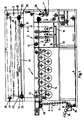
- a device for cleaning cans according to FIG. I essentially consists of a washing zone I, a rinsing zone 2 and a drying zone 3.
- Cans 4 of which only a few are shown in FIG. 1 for the sake of clarity, reach bars 5 of a transport chain 6 in a transfer station 35.
- the transfer can take place, for example, from a conveyor belt 36 via an inlet star 37 by means of vacuum.
- the transport chain 6 is a simple Gall chain consisting of outer plates 7 and inner plates 8, which are connected to one another via bolts 9. Some of these bolts are extended at a certain distance from one another to the bars 5.
- the can 4 floats around the rod 5, only the position is shown here, in which the rod 5 also happens to form approximately the central axis for the can 4.
- the transport chain 6 is introduced via a deflection roller 12 into a wash bath 13 filled with a wash liquor.
- a multiple deflection of the conveyor belt 6 then takes place in the wash bath 13 via rollers 14.
- the wash liquor should always be kept in motion, for example by means of a circulation pump, with which a more intensive washing takes place.
- the cans 4 are to be guided between the transport chain 6 and a stop bar 10.
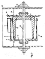
- stop disks 40 see FIG. 4).
- the stop discs 40 of adjacent rollers 14 are designed and arranged so that they rotate at a close distance from one another. The cans 4 then slide from one stop disk 40 to the next without major interruption.
- a roller 14 consists of a longitudinally conical core 41, which is traversed by a shaft 42.
- the core 41 of the shaft 42, the stop disk 40 is placed on the other hand, a gear 43 for the chain 6.
- the conical design of the core 41 with the taper towards the gear 43 causes the cans 4 to emerge from the wash liquor line 44 when the upper rollers 14 rotate and the liquor can flow out of the cans 4.
- the shaft 42 is otherwise stored outside the wash liquor container 45, bearing shells 46 being provided with corresponding seals 47 with respect to the wash liquor container 45.
- a nozzle chamber 54 extends between the stop disks 40 of two adjacent rollers 14 in the running direction of the transport chain 6, which is provided with nozzles 55 towards the transport chain 6.
- the nozzle chamber 54 is connected via a delivery line 56 to a pump 57, which fetches wash liquor from the wash bath 13 via a line 58.
- the wash liquor emerging from the nozzles 55 in this way causes the cans to be held on the rods 5. This also prevents the cans from swimming.
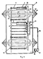
- the transport chain 6 runs out of the washing zone I Via further deflecting rollers 12 and rollers 14, first into a pre-wash basin 16, then into a main wash basin 17 and then into a post-wash basin 18. Only one roller 14 is shown in FIG. However, several rollers 14 can also be arranged here or stop strips 10 or nozzle chambers 54 can be provided.
- the cans are completely clean, for example with fresh well water d. H. 100% fat-free rinsed.
- this water from the final rinse 18 is introduced at regular intervals into the main sink 17 and the water from the main rinse at regular intervals into the pre-rinse 16, as indicated by the line 19.
- the used water can then be introduced into the sewage system via a drain 20.
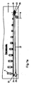
- the cans 4 on the transport chain 6 enter the drying zone 3, the transport chain 6 first looping around an input roller 21 with a horizontal roller axis 22 after a deflection roller 12.
- the chain 6 is guided from the input roller 21 to a toothed wheel 23, the axis 24 of which is arranged vertically.
- Both the axis 24 and the roller axis 22 open into a gear 25 or 26, both gears 25 and 26 being connected to one another via a gimbal-mounted gear rod 27.
- angular gearboxes should be used as gearboxes.
- connection between gear 25 and gear 26 is such that the transport chain 6 between the input roller 21 and the gear 23 takes a large part of its tension. In this way it is possible for the transport chain 6 to rotate through 90 ° between the input roller 21 and the gear 23. This rotation by 90 °, as shown in Fig. La, also follow the rods 5 and together with them the cans 4, which are thereby set up. In this position, the cans can drip off on their own and, secondly, hot air is applied to them.
- the transport chain 6 runs onto an output roller 28 with a horizontal roller axis 29.
- the axis of the gear 23 in front of the output roller 28 and the axis of the output roller 28 can also be gimbally coupled to the drives 25 and 26 for the sake of simplicity. This in turn allows the transport chain 6 to be rotated by 90 ° , which also the rods 5 and with them the cans 4 follow.
- the cans 4 are thus arranged horizontally again and reach a removal device 50 via deflection rollers 12.
- This drive 51 has a preferably cardanic coupling 52 with the drive 38.
- all drives can be connected individually or to one another via corresponding gear elements.
Claims (16)
Priority Applications (1)
| Application Number | Priority Date | Filing Date | Title |
|---|---|---|---|
| AT87106651T ATE52050T1 (de) | 1986-05-07 | 1987-05-07 | Vorrichtung zum reinigen von dosen. |
Applications Claiming Priority (4)
| Application Number | Priority Date | Filing Date | Title |
|---|---|---|---|
| DE19863615538 DE3615538A1 (de) | 1986-05-07 | 1986-05-07 | Vorrichtung zum reinigen von dosen |
| DE3615538 | 1986-05-07 | ||
| DE19863626176 DE3626176A1 (de) | 1986-08-01 | 1986-08-01 | Vorrichtung zum reinigen von dosen |
| DE3626176 | 1986-08-01 |
Publications (2)
| Publication Number | Publication Date |
|---|---|
| EP0244865A1 EP0244865A1 (fr) | 1987-11-11 |
| EP0244865B1 true EP0244865B1 (fr) | 1990-04-18 |
Family
ID=25843565
Family Applications (1)
| Application Number | Title | Priority Date | Filing Date |
|---|---|---|---|
| EP87106651A Expired - Lifetime EP0244865B1 (fr) | 1986-05-07 | 1987-05-07 | Dispositif de nettoyage de boîtes |
Country Status (7)
| Country | Link |
|---|---|
| US (1) | US4880021A (fr) |
| EP (1) | EP0244865B1 (fr) |
| JP (1) | JPS63503136A (fr) |
| AU (1) | AU7354387A (fr) |
| DE (1) | DE3762319D1 (fr) |
| ES (1) | ES2016301B3 (fr) |
| WO (1) | WO1987006921A1 (fr) |
Families Citing this family (6)
| Publication number | Priority date | Publication date | Assignee | Title |
|---|---|---|---|---|
| DE4225147A1 (de) * | 1992-02-29 | 1993-09-02 | Karl Haberstroh | Vorrichtung zum transport von gegenstaenden |
| DE19518031A1 (de) * | 1995-05-17 | 1996-11-21 | Alexander Dipl Phys Stichnoth | Verfahren zur Nutzbarmachung von gebrauchten Verdunsterampullen aus Heizkostenverteilern |
| GB9828333D0 (en) | 1998-12-23 | 1999-02-17 | Crown Cork & Seal Tech Corp | Rinsing device |
| US6581647B1 (en) | 1999-11-30 | 2003-06-24 | Hugh Leidlein | Mobile drumming apparatus and method |
| CN101875036A (zh) * | 2009-04-30 | 2010-11-03 | 深圳富泰宏精密工业有限公司 | 转动装置 |
| US8858730B2 (en) | 2011-09-06 | 2014-10-14 | Peter Chapman | Beverage can cleaning apparatus and method of use thereof |
Family Cites Families (14)
| Publication number | Priority date | Publication date | Assignee | Title |
|---|---|---|---|---|
| US1185329A (en) * | 1913-08-22 | 1916-05-30 | U S Fiber Bottle Machinery Company | Bottle-coating machine. |
| GB123769A (en) * | 1916-09-04 | 1919-10-02 | Emile Louis Alfred Savy | Improvements in Drying Apparatus for Bottles, Jars, Cans or the like Receptacles. |
| US1411288A (en) * | 1918-10-23 | 1922-04-04 | Joseph Campbell Company | Can-washing machine |
| GB305607A (en) * | 1927-11-05 | 1929-02-05 | Thomas Millar Campbell | Improvements in or relating to apparatus for treating bottles and receptacles and conveying devices for use therein |
| US2708943A (en) * | 1953-08-12 | 1955-05-24 | Acf Ind Inc | Apparatus for handling and liquid treating articles |
| US3092125A (en) * | 1958-04-16 | 1963-06-04 | Andrew H Kinsey | Container cooling apparatus |
| US3675665A (en) * | 1965-01-15 | 1972-07-11 | Ind Washing Machine Corp | Case washing machine |
| US3353515A (en) * | 1965-06-10 | 1967-11-21 | Stolle Corp | Can treating apparatus |
| US3595251A (en) * | 1968-12-26 | 1971-07-27 | Arlo Ind Inc | Container washing inverting and conveying apparatus |
| US3915285A (en) * | 1974-02-14 | 1975-10-28 | Heinz Co H J | Apparatus for spacing cans |
| NZ182304A (en) * | 1975-10-22 | 1979-03-28 | Oag Ej | Bottle cleaning apparatus:first conveyor carries cradles for bottles,second conveyor supports nozzles for cleaning fluid |
| SE7905806L (sv) * | 1979-07-03 | 1981-01-04 | Nordnero Ab | Vattenbaserat rengoringssystem |
| US4324265A (en) * | 1980-02-22 | 1982-04-13 | American Bottlers Equipment Company, Inc. | Can end washer and dryer |
| US4423745A (en) * | 1982-11-29 | 1984-01-03 | Simplimatic Engineering Company | Rinsing machine |
-
1987
- 1987-05-07 ES ES87106651T patent/ES2016301B3/es not_active Expired - Lifetime
- 1987-05-07 AU AU73543/87A patent/AU7354387A/en not_active Abandoned
- 1987-05-07 EP EP87106651A patent/EP0244865B1/fr not_active Expired - Lifetime
- 1987-05-07 JP JP62502852A patent/JPS63503136A/ja active Pending
- 1987-05-07 DE DE8787106651T patent/DE3762319D1/de not_active Expired - Fee Related
- 1987-05-07 WO PCT/DE1987/000212 patent/WO1987006921A1/fr unknown
-
1988
- 1988-01-05 US US07/148,659 patent/US4880021A/en not_active Expired - Fee Related
Also Published As
| Publication number | Publication date |
|---|---|
| ES2016301B3 (es) | 1990-11-01 |
| DE3762319D1 (de) | 1990-05-23 |
| EP0244865A1 (fr) | 1987-11-11 |
| US4880021A (en) | 1989-11-14 |
| JPS63503136A (ja) | 1988-11-17 |
| WO1987006921A1 (fr) | 1987-11-19 |
| AU7354387A (en) | 1987-12-01 |
Similar Documents
| Publication | Publication Date | Title |
|---|---|---|
| DE2330915A1 (de) | Verfahren und vorrichtung zum ausscheiden von feststoffen aus fluessigkeiten | |
| DE1432293C3 (de) | Vorrichtung zum Waschen von Flaschen mit ablösbaren Etiketten | |
| DE3527764C2 (de) | Vorrichtung zum Reinigen von textilen Lamellen für Jalousetten | |
| EP0244865B1 (fr) | Dispositif de nettoyage de boîtes | |
| DE3248555C2 (fr) | ||
| EP0170755A1 (fr) | Machine de lavage pour betteraves sucrières ou d'autres produits des champs | |
| EP0529387A1 (fr) | Machine pour le nettoyage de bouteilles ou similaires | |
| DE2045541A1 (de) | Waschvorrichtung | |
| DE2924050C2 (de) | Verfahren und Einrichtung zur Reinigung und Desinfektion von Transportbehältern | |
| DE19650944C1 (de) | Flaschenreinigungsmaschine in Doppelendbauweise | |
| DE2806126A1 (de) | Reinigungsvorrichtung | |
| DE1607629C2 (de) | Anlage zur Reinigung von Feldfrüchten | |
| DE3615538A1 (de) | Vorrichtung zum reinigen von dosen | |
| DE2248220A1 (de) | Flaschenreinigungsmaschine | |
| DE379185C (de) | Verfahren zum Reinigen und Sterilisieren von Flaschen | |
| EP0423781A2 (fr) | Dispositif pour enlever des étiquettes, des matières solides et des tessons d'un liquide de traitement d'une machine de nettoyage des récipients spécialement d'une machine de nettoyage de bouteilles | |
| DE2215334A1 (de) | Vorrichtung zum fortlaufenden aetzen von insbesondere flachen gegenstaenden | |
| DE1492411B2 (de) | Verfahren und vorrichtung zur reinigung von aerztlichen instrumenten, krankenhausgeraeten und dgl. | |
| DE2837753A1 (de) | Einrichtung zur fluessigkeitsbehandlung von massenteilen in einer rotierenden trommel | |
| DE1492411C3 (de) | Verfahren und Vorrichtung zur Reinigung von ärztlichen Instrumenten, Krankenhausgeräten und dgl | |
| DE1557582A1 (de) | Vorrichtung zum Waschen des Innenraums eines sperrigen Fluessigkeitsbehaelters | |
| DE1927223C3 (de) | Maschine zum Innenreinigen und Füllen von Bierfässern | |
| DE2119267A1 (de) | Kistenwaschmaschine | |
| WO2003082488A1 (fr) | Procede et dispositif de traitement de bouteilles en matiere plastique | |
| EP0918974B1 (fr) | Dispositif de projection intermittente d'un agent pour le traitement de surfaces |
Legal Events
| Date | Code | Title | Description |
|---|---|---|---|
| PUAI | Public reference made under article 153(3) epc to a published international application that has entered the european phase |
Free format text: ORIGINAL CODE: 0009012 |
|
| AK | Designated contracting states |
Kind code of ref document: A1 Designated state(s): AT BE CH DE ES FR GB IT LI NL SE |
|
| 17P | Request for examination filed |
Effective date: 19880511 |
|
| 17Q | First examination report despatched |
Effective date: 19890505 |
|
| GRAA | (expected) grant |
Free format text: ORIGINAL CODE: 0009210 |
|
| AK | Designated contracting states |
Kind code of ref document: B1 Designated state(s): AT BE CH DE ES FR GB IT LI NL SE |
|
| PG25 | Lapsed in a contracting state [announced via postgrant information from national office to epo] |
Ref country code: SE Effective date: 19900418 Ref country code: NL Effective date: 19900418 |
|
| REF | Corresponds to: |
Ref document number: 52050 Country of ref document: AT Date of ref document: 19900515 Kind code of ref document: T |
|
| PG25 | Lapsed in a contracting state [announced via postgrant information from national office to epo] |
Ref country code: AT Effective date: 19900507 |
|
| REF | Corresponds to: |
Ref document number: 3762319 Country of ref document: DE Date of ref document: 19900523 |
|
| PG25 | Lapsed in a contracting state [announced via postgrant information from national office to epo] |
Ref country code: BE Effective date: 19900531 |
|
| ET | Fr: translation filed | ||
| ITF | It: translation for a ep patent filed |
Owner name: DE DOMINICIS & MAYER S.R.L. |
|
| GBT | Gb: translation of ep patent filed (gb section 77(6)(a)/1977) | ||
| NLV1 | Nl: lapsed or annulled due to failure to fulfill the requirements of art. 29p and 29m of the patents act | ||
| BERE | Be: lapsed |
Owner name: LECHNER G.M.B.H. Effective date: 19900531 |
|
| PLBE | No opposition filed within time limit |
Free format text: ORIGINAL CODE: 0009261 |
|
| STAA | Information on the status of an ep patent application or granted ep patent |
Free format text: STATUS: NO OPPOSITION FILED WITHIN TIME LIMIT |
|
| 26N | No opposition filed | ||
| ITTA | It: last paid annual fee | ||
| PGFP | Annual fee paid to national office [announced via postgrant information from national office to epo] |
Ref country code: GB Payment date: 19980414 Year of fee payment: 12 |
|
| PGFP | Annual fee paid to national office [announced via postgrant information from national office to epo] |
Ref country code: FR Payment date: 19980417 Year of fee payment: 12 |
|
| PGFP | Annual fee paid to national office [announced via postgrant information from national office to epo] |
Ref country code: ES Payment date: 19980518 Year of fee payment: 12 Ref country code: CH Payment date: 19980518 Year of fee payment: 12 |
|
| PGFP | Annual fee paid to national office [announced via postgrant information from national office to epo] |
Ref country code: DE Payment date: 19980527 Year of fee payment: 12 |
|
| PG25 | Lapsed in a contracting state [announced via postgrant information from national office to epo] |
Ref country code: GB Free format text: LAPSE BECAUSE OF NON-PAYMENT OF DUE FEES Effective date: 19990507 |
|
| PG25 | Lapsed in a contracting state [announced via postgrant information from national office to epo] |
Ref country code: ES Free format text: LAPSE BECAUSE OF NON-PAYMENT OF DUE FEES Effective date: 19990508 |
|
| PG25 | Lapsed in a contracting state [announced via postgrant information from national office to epo] |
Ref country code: LI Free format text: LAPSE BECAUSE OF NON-PAYMENT OF DUE FEES Effective date: 19990531 Ref country code: CH Free format text: LAPSE BECAUSE OF NON-PAYMENT OF DUE FEES Effective date: 19990531 |
|
| GBPC | Gb: european patent ceased through non-payment of renewal fee |
Effective date: 19990507 |
|
| REG | Reference to a national code |
Ref country code: CH Ref legal event code: PL |
|
| PG25 | Lapsed in a contracting state [announced via postgrant information from national office to epo] |
Ref country code: FR Free format text: LAPSE BECAUSE OF NON-PAYMENT OF DUE FEES Effective date: 20000131 |
|
| PG25 | Lapsed in a contracting state [announced via postgrant information from national office to epo] |
Ref country code: DE Free format text: LAPSE BECAUSE OF NON-PAYMENT OF DUE FEES Effective date: 20000301 |
|
| REG | Reference to a national code |
Ref country code: FR Ref legal event code: ST |
|
| REG | Reference to a national code |
Ref country code: ES Ref legal event code: FD2A Effective date: 20010503 |
|
| PG25 | Lapsed in a contracting state [announced via postgrant information from national office to epo] |
Ref country code: IT Free format text: LAPSE BECAUSE OF NON-PAYMENT OF DUE FEES;WARNING: LAPSES OF ITALIAN PATENTS WITH EFFECTIVE DATE BEFORE 2007 MAY HAVE OCCURRED AT ANY TIME BEFORE 2007. THE CORRECT EFFECTIVE DATE MAY BE DIFFERENT FROM THE ONE RECORDED. Effective date: 20050507 |