EP0244865B1 - Apparatus for cleaning cans - Google Patents
Apparatus for cleaning cans Download PDFInfo
- Publication number
- EP0244865B1 EP0244865B1 EP87106651A EP87106651A EP0244865B1 EP 0244865 B1 EP0244865 B1 EP 0244865B1 EP 87106651 A EP87106651 A EP 87106651A EP 87106651 A EP87106651 A EP 87106651A EP 0244865 B1 EP0244865 B1 EP 0244865B1
- Authority
- EP
- European Patent Office
- Prior art keywords
- cans
- zone
- conveying chain
- rinsing
- washing
- Prior art date
- Legal status (The legal status is an assumption and is not a legal conclusion. Google has not performed a legal analysis and makes no representation as to the accuracy of the status listed.)
- Expired - Lifetime
Links
Images

Classifications
-
- B—PERFORMING OPERATIONS; TRANSPORTING
- B08—CLEANING
- B08B—CLEANING IN GENERAL; PREVENTION OF FOULING IN GENERAL
- B08B9/00—Cleaning hollow articles by methods or apparatus specially adapted thereto
- B08B9/08—Cleaning containers, e.g. tanks
- B08B9/20—Cleaning containers, e.g. tanks by using apparatus into or on to which containers, e.g. bottles, jars, cans are brought
- B08B9/42—Cleaning containers, e.g. tanks by using apparatus into or on to which containers, e.g. bottles, jars, cans are brought the apparatus being characterised by means for conveying or carrying containers therethrough
Definitions
- the invention relates to a device for cleaning cans or the like.
- Containers which are guided in an approximately horizontal position, for example on bars of a transport chain, via rollers or deflection rollers through a washing zone and a rinsing zone.
- the cans are rinsed in different rinsing zones, with the cans here also being guided through the rinsing zones by the transport chain via deflection rollers.
- the inventor has set itself the goal of developing a device of the type mentioned above, in which the cans can be safely guided through the washing and rinsing baths and through a drying zone from the same transport chain, and are reliably dried there.
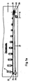
- the transport chain runs into a drying zone after the rinsing zone, in which the cans are guided with the can opening downwards in the installed position.
- the transport chain wraps around an input roller with a horizontal roller axis when entering the drying zone and is then guided approximately horizontally to a gearwheel with a vertical axis.
- the change from the input roller with the horizontal roller axis to the gearwheel with the vertical axis leads to a rotation of the transport chain by 90 ° .
- the bars on the transport chain also rotate, thus erecting the cans.
- both the roller axis of the input roller and the axis of the gear are each driven by a synchronously running gear. Furthermore, the transport chain between the input roller and the gearwheel should be under a reduced tension, which is maintained by the two synchronously running gears over the entire life of the device.
- the arrangement of an angular gear is preferred, it being possible for both gears to be connected to one another via a gimbal-arranged gear rod or cardan shaft to ensure their synchronous running.
- This cardanically arranged cardan shaft definitely guarantees a permanent synchronous running or the reduced chain tension.
- the reduced chain tension in turn means that the transport chain can turn through 90 ° without being damaged.
- the transport chain is guided at the end of the drying zone from a gearwheel with a vertical axis to an output roller with a horizontal roller axis.
- the cans are turned over again, the tension of the transport chain also having to be reduced here, which can be brought about by the gears mentioned above, which are also assigned to the output roller and the gearwheel.
- swimming off of the cans is to be prevented both in the washing zone and in the rinsing zone, in particular as a result of movements in the washing bath or rinsing bath.
- extraneous water, air or the like can be used as the medium.
- Air for example, could have the advantage that a certain turbulence is generated by the formation of bubbles in the wash liquor, which causes a better washing effect for the cans.
- turbulence can in turn become too violent, so that the cans rotate around the bars and, for example, strike the bars too strongly with their opening edge on the bars. Therefore a liquid medium is preferred.
- the wash liquor itself is used in the wash zone and the rinse water in the rinse zone.
- the nozzles are arranged on a nozzle chamber which extends in the running direction of the transport chain, so that the cans are accompanied by nozzles as long as possible during their circulation.
- the nozzle chamber is then connected via a delivery line to a pump for delivering the medium, in this case the wash liquor or the rinsing water, the pump fetching this medium from the wash bath or the sink via a further line.
- the transport chain can be accompanied by stop bars which prevent swimming.
- roller core between the stop washer and the gearwheel should be conical, so that the can, which is in contact with this core when it emerges from the wash liquor or rinsing water line, is emptied.
- the invention provides that the storage of the rollers outside of the washing or. the sink is done.
- appropriate seals are provided against the individual basins.
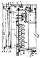
- a device for cleaning cans according to FIG. I essentially consists of a washing zone I, a rinsing zone 2 and a drying zone 3.
- Cans 4 of which only a few are shown in FIG. 1 for the sake of clarity, reach bars 5 of a transport chain 6 in a transfer station 35.
- the transfer can take place, for example, from a conveyor belt 36 via an inlet star 37 by means of vacuum.
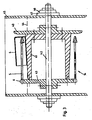
- the transport chain 6 is a simple Gall chain consisting of outer plates 7 and inner plates 8, which are connected to one another via bolts 9. Some of these bolts are extended at a certain distance from one another to the bars 5.
- the can 4 floats around the rod 5, only the position is shown here, in which the rod 5 also happens to form approximately the central axis for the can 4.
- the transport chain 6 is introduced via a deflection roller 12 into a wash bath 13 filled with a wash liquor.
- a multiple deflection of the conveyor belt 6 then takes place in the wash bath 13 via rollers 14.
- the wash liquor should always be kept in motion, for example by means of a circulation pump, with which a more intensive washing takes place.
- the cans 4 are to be guided between the transport chain 6 and a stop bar 10.
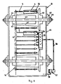
- stop disks 40 see FIG. 4).
- the stop discs 40 of adjacent rollers 14 are designed and arranged so that they rotate at a close distance from one another. The cans 4 then slide from one stop disk 40 to the next without major interruption.
- a roller 14 consists of a longitudinally conical core 41, which is traversed by a shaft 42.
- the core 41 of the shaft 42, the stop disk 40 is placed on the other hand, a gear 43 for the chain 6.
- the conical design of the core 41 with the taper towards the gear 43 causes the cans 4 to emerge from the wash liquor line 44 when the upper rollers 14 rotate and the liquor can flow out of the cans 4.
- the shaft 42 is otherwise stored outside the wash liquor container 45, bearing shells 46 being provided with corresponding seals 47 with respect to the wash liquor container 45.
- a nozzle chamber 54 extends between the stop disks 40 of two adjacent rollers 14 in the running direction of the transport chain 6, which is provided with nozzles 55 towards the transport chain 6.
- the nozzle chamber 54 is connected via a delivery line 56 to a pump 57, which fetches wash liquor from the wash bath 13 via a line 58.
- the wash liquor emerging from the nozzles 55 in this way causes the cans to be held on the rods 5. This also prevents the cans from swimming.
- the transport chain 6 runs out of the washing zone I Via further deflecting rollers 12 and rollers 14, first into a pre-wash basin 16, then into a main wash basin 17 and then into a post-wash basin 18. Only one roller 14 is shown in FIG. However, several rollers 14 can also be arranged here or stop strips 10 or nozzle chambers 54 can be provided.
- the cans are completely clean, for example with fresh well water d. H. 100% fat-free rinsed.
- this water from the final rinse 18 is introduced at regular intervals into the main sink 17 and the water from the main rinse at regular intervals into the pre-rinse 16, as indicated by the line 19.
- the used water can then be introduced into the sewage system via a drain 20.
- the cans 4 on the transport chain 6 enter the drying zone 3, the transport chain 6 first looping around an input roller 21 with a horizontal roller axis 22 after a deflection roller 12.
- the chain 6 is guided from the input roller 21 to a toothed wheel 23, the axis 24 of which is arranged vertically.
- Both the axis 24 and the roller axis 22 open into a gear 25 or 26, both gears 25 and 26 being connected to one another via a gimbal-mounted gear rod 27.
- angular gearboxes should be used as gearboxes.
- connection between gear 25 and gear 26 is such that the transport chain 6 between the input roller 21 and the gear 23 takes a large part of its tension. In this way it is possible for the transport chain 6 to rotate through 90 ° between the input roller 21 and the gear 23. This rotation by 90 °, as shown in Fig. La, also follow the rods 5 and together with them the cans 4, which are thereby set up. In this position, the cans can drip off on their own and, secondly, hot air is applied to them.
- the transport chain 6 runs onto an output roller 28 with a horizontal roller axis 29.
- the axis of the gear 23 in front of the output roller 28 and the axis of the output roller 28 can also be gimbally coupled to the drives 25 and 26 for the sake of simplicity. This in turn allows the transport chain 6 to be rotated by 90 ° , which also the rods 5 and with them the cans 4 follow.
- the cans 4 are thus arranged horizontally again and reach a removal device 50 via deflection rollers 12.
- This drive 51 has a preferably cardanic coupling 52 with the drive 38.
- all drives can be connected individually or to one another via corresponding gear elements.
Description
Die Erfindung betrifft eine Vorrichtung zum Reinigen von Dosen od. dgl. Behältnisse, welche in etwa waagrechter Lage beispielsweise an Stäben einer Transportkette über Walzen bzw. Umlenkrolle durch eine Waschzone und eine Spülzone geführt sind.The invention relates to a device for cleaning cans or the like. Containers which are guided in an approximately horizontal position, for example on bars of a transport chain, via rollers or deflection rollers through a washing zone and a rinsing zone.
Ein industrielles Reinigen von Dosen findet heute in der Regel in einer Waschzone statt, wobei die zu reinigenden Dosen über verschiedene Umlenkwalzen durch die Waschzone geführt werden. Damit die Waschlauge in das Doseninnere gelangen kann, sollte die Dose zumindest in waagrechter Lage geführt sein.Industrial cleaning of cans today usually takes place in a washing zone, with the cans to be cleaned being passed through the washing zone via various deflecting rollers. So that the washing liquor can get into the interior of the can, the can should at least be guided in a horizontal position.
Nach der Waschzone erfolgt ein Spülen der Dosen in verschiedenen Spülzonen, wobei auch hier die Dosen von der Transportkette über Umlenkwalzen durch die Spülzonen geführt werden. Dies geschieht selbstverständlich in zumindest waagrechter Lage der Dosen, wobei diese gegen ein Abschwimmen gesichert sein müssen.After the washing zone, the cans are rinsed in different rinsing zones, with the cans here also being guided through the rinsing zones by the transport chain via deflection rollers. Of course, this happens in at least a horizontal position of the cans, which must be secured against floating.
Danach ist es heute üblich, die Dosen von der Transportkette zu nehmen und einem speziellen Trockenraum zuzuführen. Dies hat allerdings den Nachteil, daß zusätzliche Arbeitsschritte für das Abnehmen der Dose von der Transportkette und dem Zuführen zum Trockenraum vorgesehen sind. Andererseits würde ein Weiterführen der Transportkette durch eine Trockenzone den Nachteil mit sich bringen, daß die Dosen ihre waagrechte Stellung beibehalten und sich so Spülflüssigkeit im Doseninneren halten kann, die in der Trockenzone nicht abtrocknet. Dies beeinträchtigt eine weitere Bearbeitung der Dose, wie beispielsweise eine Innenversiegelung.After that, it is common today to remove the cans from the transport chain and feed them to a special drying room. However, this has the disadvantage that additional work steps are provided for removing the can from the transport chain and feeding it to the drying room. On the other hand, a continuation of the transport chain through a drying zone would entail the disadvantage that the cans can maintain their horizontal position and thus hold rinsing liquid inside the can, which does not dry out in the drying zone. This affects further processing of the can, such as an internal seal.
Der Erfinder hat sich zum Ziel gesetzt, eine Vorrichtung der oben genannten Art zu entwickeln, bei welcher die Dosen von der gleichen Transportkette sicher durch alle Wasch- und Spülbäder und durch eine Trockenzone geführt werden können und dort zuverlässig abgetrocknet werden.The inventor has set itself the goal of developing a device of the type mentioned above, in which the cans can be safely guided through the washing and rinsing baths and through a drying zone from the same transport chain, and are reliably dried there.
Zur Lösung dieser Aufgabe führt, daß die Transportkette nach der Spülzone in eine Trockenzone einläuft, in der die Dosen in aufgestellter Lage mit der Dosenöffnung nach unten geführt sind.To achieve this object, the transport chain runs into a drying zone after the rinsing zone, in which the cans are guided with the can opening downwards in the installed position.
Hierdurch erübrigt sich ein Abnehmen der Dosen von der Transportkette nach der Spülzone und gleichzeitig läuft in der Trockenzone aus der Dose das meiste Spülwasser sofort ab, das übrige kann durch die in der Trockenzone vorhandene Heißluft leicht entfernt werden.This eliminates the need to remove the cans from the transport chain to the rinsing zone and, at the same time, most of the rinsing water runs out of the can in the drying zone, the rest can be easily removed by the hot air in the drying zone.
Um ein Aufstellen der Dosen in der Trockenzone zu erreichen ist erfindungsgemäß vorgesehen, daß die Transportkette beim Einlauf in die Trockenzone eine Eingangswalze mit waagrechter Walzenachse umschlingt und danach etwa waagrecht zu einem Zahnrad mit senkrechter Achse geführt ist. Der Wechsel von der Eingangswalze mit waagrechter Walzenachse auf das Zahnrad mit senkrechter Achse führt zu einem Drehen der Transportkette um 90°. Mit der Transportkette drehen aber auch die Stäbe an der Transportkette und richten so die Dosen auf. Bei einer derartigen Transportkette, wie sie für den Transport von Dosen verwendet wird, stellt sich jedoch die Schwierigkeit, daß die Kette bei gleichbleibender Kettenspannung zwischen zwei Walzen nicht um 90° gedreht werden kann. Ein gewaltsames Drehen würde zu einem erhöhten Verschleiß der Kette führen. Aus diesem Grunde ist erfindungsgemäß vorgesehen, daß sowohl die Walzenachse der Eingangswalze wie auch die Achse des Zahnrades von je einem synchron laufenden Getriebe angetrieben werden. Weiterhin soll die Transportkette zwischen der Eingangswalze und dem Zahnrad unter einer verminderten Spannung stehen, die von den beiden synchron laufenden Getrieben über die gesamte Lebensdauer der Vorrichtung aufrecht erhalten wird.In order to set up the cans in the drying zone, it is provided according to the invention that the transport chain wraps around an input roller with a horizontal roller axis when entering the drying zone and is then guided approximately horizontally to a gearwheel with a vertical axis. The change from the input roller with the horizontal roller axis to the gearwheel with the vertical axis leads to a rotation of the transport chain by 90 ° . With the transport chain, however, the bars on the transport chain also rotate, thus erecting the cans. With such a transport chain, as it is used for the transport of cans, there is the difficulty that the chain cannot be rotated by 90 ° with the chain tension remaining between two rollers. A violent rotation would lead to increased wear of the chain. For this reason, it is provided according to the invention that both the roller axis of the input roller and the axis of the gear are each driven by a synchronously running gear. Furthermore, the transport chain between the input roller and the gearwheel should be under a reduced tension, which is maintained by the two synchronously running gears over the entire life of the device.
Bevorzugt wird die Anordnung eines Winkelgetriebes, wobei beide Getriebe zur Gewährleistung ihres synchronen Laufs über eine kardanisch angeordnete Getriebestange bzw. Gelenkwelle miteinander verbunden sein können. Diese kardanisch angeordnete Gelenkwelle gewährleistet auf jeden Fall einen immerwährenden synchronen Lauf bzw. die verminderte Kettenspannung. Die verminderte Kettenspannung wiederum hat zur Folge, daß sich die Transportkette um 90° drehen kann, ohne Schaden zu nehmen.The arrangement of an angular gear is preferred, it being possible for both gears to be connected to one another via a gimbal-arranged gear rod or cardan shaft to ensure their synchronous running. This cardanically arranged cardan shaft definitely guarantees a permanent synchronous running or the reduced chain tension. The reduced chain tension in turn means that the transport chain can turn through 90 ° without being damaged.
Nach der Trockenzone wird es in der Regel wiederum notwendig sein, daß die Dosen in waagrechter Lage einer Abnahmevorrichtung zugeführt werden. Deswegen ist erfindungsgemäß vorgesehen, daß die Transportkette am Ende der Trockenzone von einem Zahnrad mit senkrechter Achse auf eine Ausgangswalze mit waagrechter Walzenachse geführt ist. Hierdurch erfolgt also wieder ein Umlegen der Dosen, wobei auch hier die Spannung der Transportkette vermindert sein muß, was durch die oben genannten, auch der Ausgangswalze und dem Zahnrad zugeordneten Getriebe bewirkt werden kann.After the drying zone, it will generally be necessary again for the cans to be fed to a removal device in a horizontal position. For this reason, it is provided according to the invention that the transport chain is guided at the end of the drying zone from a gearwheel with a vertical axis to an output roller with a horizontal roller axis. As a result, the cans are turned over again, the tension of the transport chain also having to be reduced here, which can be brought about by the gears mentioned above, which are also assigned to the output roller and the gearwheel.
Selbstverständlich ist es möglich, das Aufrichten der Dosen durch seitlich an der Transportkette verlaufende Führungsschienen zu unterstützen.Of course, it is possible to support the erection of the cans with guide rails running along the side of the transport chain.
Weiterhin soll sowohl in der Waschzone wie auch in der Spülzone ein Abschwimmen, insbesondere infolge von Waschbad- bzw. Spülbadbewegungen, der Dosen verhindert werden.Furthermore, swimming off of the cans is to be prevented both in the washing zone and in the rinsing zone, in particular as a result of movements in the washing bath or rinsing bath.
Dies geschieht einmal durch zwischen zwei aufeinanderfolgenden Walzen gegenüber der Transportkette angeordnete Düsen, welche die Dosenböden mit einem Medium beaufschlagen.This takes place once through nozzles arranged between two successive rollers opposite the transport chain, which act on the can bottoms with a medium.
Hierdurch wird verhindert, daß die Dosen von den Stabspitzen abheben. Durch die Beaufschlagung mit dem Medium werden sie in ständigem Kontakt mit den Stabspitzen gehalten.This prevents the cans from lifting off the rod tips. The medium is kept in constant contact with the rod tips.
Erfindungsgemäß kann als Medium Fremdwasser, Luft od. dgl. Anwendung finden. Luft könnte beispielsweise den Vorteil haben, daß durch die Blasenbildung in der Waschlauge eine gewisse Turbulenz erzeugt wird, welche einen besseren Wascheffekt für die Dosen bewirkt. Allerdings können Turbulenzen hier wiederum zu heftig werden, so daß es zu einem Rotieren der Dosen um die Stäbe kommt und diese beispielsweise mit ihrem Öffnungsrand zu stark an den Stäben anschlagen. Deshalb wird ein flüssiges Medium bevorzugt. Erfindungsgemäß wird dabei in der Waschzone auf die Waschlauge selbst bzw. in der Spülzone auf das Spülwasser zurückgegriffen. Hierzu ist vorgesehen, daß die Düsen an einer Düsenkammer angeordnet sind, welche sich in Laufrichtung der Transportkette erstreckt, damit die Dosen möglichst lange während ihres Umlaufes von Düsen begleitet sind. Die Düsenkammer ist dann über eine Förderleitung mit einer Pumpe zum Fördern des Mediums, in diesem Fall der Waschlauge bzw. des Spülwassers verbunden, wobei sich die Pumpe dieses Medium über eine weitere Leitung aus dem Waschbad bzw. dem Spülbecken holt.According to the invention, extraneous water, air or the like can be used as the medium. Air, for example, could have the advantage that a certain turbulence is generated by the formation of bubbles in the wash liquor, which causes a better washing effect for the cans. However, turbulence can in turn become too violent, so that the cans rotate around the bars and, for example, strike the bars too strongly with their opening edge on the bars. Therefore a liquid medium is preferred. According to the invention the wash liquor itself is used in the wash zone and the rinse water in the rinse zone. For this purpose it is provided that the nozzles are arranged on a nozzle chamber which extends in the running direction of the transport chain, so that the cans are accompanied by nozzles as long as possible during their circulation. The nozzle chamber is then connected via a delivery line to a pump for delivering the medium, in this case the wash liquor or the rinsing water, the pump fetching this medium from the wash bath or the sink via a further line.
Ferner kann erfindungsgemäß die Transportkette von Anschlagleisten begleitet sein, die ein Abschwimmen verhindern.Furthermore, according to the invention, the transport chain can be accompanied by stop bars which prevent swimming.
Als besonders wirkungsvoll hat es sich erwiesen, die entsprechenden Walzen der Transportkette in der Waschbzw. Spülzone mit Anschlagscheiben zu versehen. Die Dose wird dann zwischen dem in die Kettenglieder eingreifenden Zahnrad und der Anschlagscheibe geführt. Anschlagscheiben benachbarter Walzen laufen so nahe beieinander, daß die Dosen von einer Walze zur anderen ohne wesentlichen Unterbruch übergeben werden. Hierdurch wird ein Abschwimmen der Dosen vermieden.It has proven to be particularly effective to use the corresponding rollers in the transport chain in the washing or Wash zone to be provided with stop washers. The box is then guided between the toothed wheel engaging in the chain links and the stop disk. Stop discs of adjacent rollers run so close together that the cans are passed from one roller to the other without any significant interruption. This prevents the cans from floating off.
Weiterhin soll der Walzenkern zwischen Anschlagscheibe und Zahnrad konisch ausgebildet sein, so daß die Dose, welche beim Austritt aus der Waschlaugen- bzw. Spülwasserlinie diesem Kern anliegt, entleert wird.Furthermore, the roller core between the stop washer and the gearwheel should be conical, so that the can, which is in contact with this core when it emerges from the wash liquor or rinsing water line, is emptied.
Im übrigen ist erfindungsgemäß vorgesehen, daß die Lagerung der Walzen außerhalb des Waschbzw. der Spülbecken erfolgt. Hierzu sind entsprechende Dichtungen gegenüber den einzelnen Becken vorgesehen.In addition, the invention provides that the storage of the rollers outside of the washing or. the sink is done. For this purpose, appropriate seals are provided against the individual basins.
Im Einzelfall wird es sich als günstig erweisen, den Umlauf der Transportkette durch weitere Antriebe zu unterstützen. Auch diese Antriebe können zur Vergleichmäßigung ihres Laufes mit entsprechenden Getriebeelementen gekoppelt sein, so daß die Kette immer die gewünschte Spannung beibehält, die es erlaubt, daß die Stäbe trotz ihrer ungünstigen Hebelwirkung in waagrechter Lage gehalten werden.In individual cases, it will prove beneficial to support the circulation of the transport chain with additional drives. These drives can also be coupled with corresponding gear elements to make their run more uniform, so that the chain always maintains the desired tension, which allows the bars to be held in a horizontal position despite their unfavorable leverage.
Weitere Vorteile, Merkmale und Einzelheiten der Erfindung ergeben sich aus der nachfolgenden Beschreibung bevorzugter Ausführungsbeispiele sowie anhand der Zeichnung; diese zeigt in
- Figur I eine schematische Seitenansicht einer erfindungsgemäßen Vorrichtung zum Reinigen von Dosen;
- Figur la eine schematische Seitenansicht eines Teils der Vorrichtung nach Figur I;
Figur 2 eine vergrößert dargestellte, teilweise gebrochene Seitenansicht eines Ausschnitts aus Figur 1;- Figur 3 einen Querschnitt durch ein vergrößert dargestelltes Detail nach Fig. I entlang Linie 111-111;
Figur 4 einen Querschnitt durch ein Waschbad.
- Figure I is a schematic side view of an inventive device for cleaning cans;
- Figure la is a schematic side view of part of the device of Figure I;
- FIG. 2 shows an enlarged, partially broken side view of a detail from FIG. 1;
- 3 shows a cross section through an enlarged detail according to FIG. I along line 111-111;
- Figure 4 shows a cross section through a washing bath.
Eine erfindungsgemäße Vorrichtung zum Reinigen von Dosen besteht gemäß Fig. I im wesentlichen aus einer Waschzone I, einer Spülzone 2 und einer Trockenzone 3.A device for cleaning cans according to FIG. I essentially consists of a washing zone I, a
Dosen 4 von denen in Figur 1 der Übersichtlichkeit halber nur einige dargestellt sind, gelangen in einer Übergabestation 35 auf Stäbe 5 einer Transportkette 6. Die Übergabe kann beispielsweise von einem Transportband 36 über einen Einlaufstern 37 mittels Vakuum erfolgen.
Im Ausführungsbeispiel nach Figur 3 ist die Transportkette 6 eine einfache Gall'sche Kette aus äußeren Laschen 7 und inneren Laschen 8, die über Bolzen 9 miteinander verbunden sind. Einige dieser Bolzen sind in einem gewissen Abstand voneinander zu den Stäben 5 verlängert. In Figur 3 schwimmt die Dose 4 um den Stab 5, wobei hier nur die Lage dargestellt ist, in der der Stab 5 zufällig auch etwa die Mittelachse für die Dose 4 bildet.In the exemplary embodiment according to FIG. 3, the transport chain 6 is a simple Gall chain consisting of outer plates 7 and inner plates 8, which are connected to one another via bolts 9. Some of these bolts are extended at a certain distance from one another to the
Nach dem Einlauf II wird die Transportkette 6 über eine Umlenkrolle 12 in ein Waschbad 13, gefüllt mit einer Waschlauge, eingeleitet. In dem Waschbad 13 erfolgt dann eine mehrfache Umlenkung des Transportbandes 6 über Walzen 14. In diesem Waschbad sollte die Waschlauge beispielsweise durch eine Umwälzpumpe immer in Bewegung gehalten werden, womit ein intensiveres Waschen stattfindet. Damit ein Abschwimmen der Dosen 4 beim etwa waagrechten Führen an den Stäben 5 der Transportkette 6 verhindert wird, ist einmal an eine Führung der Dosen 4 zwischen der Transportkette 6 und einer Anschlagleiste 10 gedacht. Beim Umlaufen um die Walzen 14 wird diese Führung von Anschlagscheiben 40 (siehe Fig. 4) übernommen. Die Anschlagscheiben 40 benachbarter Walzen 14 sind so ausgebildet und angeordnet, daß sie in nahem Abstand zueinander drehen. Die Dosen 4 gleiten dann von einer Anschlagscheibe 40 ohne größere Unterbrechung zur nächsten.After the inlet II, the transport chain 6 is introduced via a
Im übrigen besteht eine Walze 14 aus einem längsschnittlich konischen Kern 41, der von einer Welle 42 durchzogen ist. Einerseits des Kerns 41 ist der Welle 42 die Anschlagscheibe 40 andererseits ein Zahnrad 43 für die Kette 6 aufgesetzt. Die konische Ausbildung des Kerns 41 mit der Verjüngung zum Zahnrad 43 hin bewirkt, daß die Dosen 4 beim Umlaufen der oberen Walzen 14 aus der Waschlaugenlinie 44 heraustauchen und die Lauge aus den Dosen 4 abfließen kann.Otherwise, a
Die Lagerung der Welle 42 erfolgt im übrigen außerhalb des Waschlaugenbehälters 45, wobei Lagerschalen 46 mit entsprechenden Dichtungen 47 gegenüber dem Waschlaugenbehälter 45 versehen sind.The
Anstelle von Anschlagleisten 10 erstreckt sich gemäß Fig. 4 zwischen den Anschlagscheiben 40 zweier benachbarter Walzen 14 in Laufrichtung der Transportkette 6 eine Düsenkammer 54, welche zur Transportkette 6 hin mit Düsen 55 versehen ist. Die Düsenkammer 54 steht über eine Förderleitung 56 mit einer Pumpe 57 in Verbindung, welche über eine Leitung 58 Waschlauge aus dem Waschbad 13 holt. Die auf diese Weise aus den Düsen 55 austretende Waschlauge bewirkt, daß die Dosen auf den Stäben 5 gehalten werden. Ein Abschwimmen der Dosen wird damit ebenso verhindert.Instead of stop bars 10, a nozzle chamber 54 extends between the
Aus der Waschzone I läuft die Transportkette 6 über weitere Umlenkrollen 12 sowie Walzen 14 zuerst in ein Vorspülbecken 16, sodann in ein Hauptspülbecken 17 und danach in ein Nachspülbecken 18 ein. In Figur I sind nur je eine Walze 14 gezeigt. Es können aber auch hier mehrere Walzen 14 angeordnet oder Anschlagleisten 10 bzw. Düsenkammern 54 vorgesehen sein.The transport chain 6 runs out of the washing zone I Via further deflecting
Im Nachspülbecken 18 werden die Dosen beispielsweise mit frischem Brunnenwasser völlig sauber d. h. 100 % fettfrei gespült. Erfindungsgemäß ist daran gedacht dieses Wasser aus dem Nachspülbecken 18 in regelmäßigen Abständen in das Hauptspülbecken 17 und das Wasser aus dem Hauptspülbecken in regelmäßigen Abständen in das Vorspülbecken 16 einzuleiten, wie dies durch die Leitung 19 angedeutet ist.In the rinse
Danach kann das verbrauchte Wasser in die Kanalisation über einen Abfluß 20 eingeleitet werden.The used water can then be introduced into the sewage system via a
Aus dem Nachspülbecken 18 gelangen die Dosen 4 an der Transportkette 6 in die Trockenzone 3, wobei die Transportkette 6 zuerst nach einer Umlenkrolle 12 eine Eingangswalze 21 mit waagerechter Walzenachse 22 umschlingt. Von der Eingangswalze 21 wird die Kette 6 zu einem Zahnrad 23 geführt, dessen Achse 24 senkrecht angeordnet ist. Sowohl die Achse 24 wie auch die Walzenachse 22 münden in ein Getriebe 25 bzw. 26, wobei beide Getriebe 25 und 26 über eine kardanisch aufgehängte Getriebestange 27 miteinander verbunden sind. Als Getriebe dürften im Regelfall Winkelgetriebe Anwendung finden.From the rinsing
Die Verbindung zwischen Getriebe 25 und Getriebe 26 erfolgt so, daß der Transportkette 6 zwischen der Eingangswalze 21 und dem Zahnrad 23 ein Großteil ihrer Spannung genommen wird. Auf diese Weise ist es möglich, daß die Transportkette 6 zwischen der Eingangswalze 21 und dem Zahnrad 23 eine Drehung um 90° vollzieht. Dieser Drehung um 90° folgen, wie in Fig. la dargestellt, auch die Stäbe 5 und mit ihnen zusammen die Dosen 4, die hierdurch aufgestellt werden. In dieser Stellung können die Dosen einmal von alleine abtropfen und zum zweiten werden sie mit Heißluft beaufschlagt.The connection between gear 25 and
Nach in Figur I gezeigter mehrfacher Umlenkung der Transportkette 6 über Zahnräder 23 läuft die Transportkette 6 auf eine Ausgangswalze 28 mit waagrechter Walzenachse 29 auf.After multiple deflection of the transport chain 6 via
Die Achse des Zahnrades 23 vor der Ausgangswalze 28 und die Achse der Ausgangswalze 28 können der Einfachheit halber ebenfalls kardanisch mit den Antrieben 25 bzw. 26 gekoppelt sein. Dies läßt wiederum ein Drehen der Transportkette 6 um 90° zu, der auch die Stäbe 5 und mit ihnen die Dosen 4 folgen. Damit sind die Dosen 4 wieder waagrecht angeordnet und gelangen über Umlenkrollen 12 zu einer Abnahmevorrichtung 50.The axis of the
Nach der Abnahmevorrichtung 50 ist die Transportkette 6 über einen weiteren Antrieb 51 zurück zur Übergabestation 35 geführt. Dieser Antrieb 51 weist eine bevorzugt kardanische Kopplung 52 mit dem Antrieb 38 auf. Im übrigen können alle Antriebe einzeln oder miteinander über entsprechende Getriebeelemente verbunden sein.After the
Claims (16)
Priority Applications (1)
| Application Number | Priority Date | Filing Date | Title |
|---|---|---|---|
| AT87106651T ATE52050T1 (en) | 1986-05-07 | 1987-05-07 | DEVICE FOR CLEANING CANS. |
Applications Claiming Priority (4)
| Application Number | Priority Date | Filing Date | Title |
|---|---|---|---|
| DE3615538 | 1986-05-07 | ||
| DE19863615538 DE3615538A1 (en) | 1986-05-07 | 1986-05-07 | Apparatus for cleaning cans |
| DE19863626176 DE3626176A1 (en) | 1986-08-01 | 1986-08-01 | Device for cleaning cans |
| DE3626176 | 1986-08-01 |
Publications (2)
| Publication Number | Publication Date |
|---|---|
| EP0244865A1 EP0244865A1 (en) | 1987-11-11 |
| EP0244865B1 true EP0244865B1 (en) | 1990-04-18 |
Family
ID=25843565
Family Applications (1)
| Application Number | Title | Priority Date | Filing Date |
|---|---|---|---|
| EP87106651A Expired - Lifetime EP0244865B1 (en) | 1986-05-07 | 1987-05-07 | Apparatus for cleaning cans |
Country Status (7)
| Country | Link |
|---|---|
| US (1) | US4880021A (en) |
| EP (1) | EP0244865B1 (en) |
| JP (1) | JPS63503136A (en) |
| AU (1) | AU7354387A (en) |
| DE (1) | DE3762319D1 (en) |
| ES (1) | ES2016301B3 (en) |
| WO (1) | WO1987006921A1 (en) |
Families Citing this family (6)
| Publication number | Priority date | Publication date | Assignee | Title |
|---|---|---|---|---|
| DE4225147A1 (en) * | 1992-02-29 | 1993-09-02 | Karl Haberstroh | DEVICE FOR TRANSPORTING OBJECTS |
| DE19518031A1 (en) * | 1995-05-17 | 1996-11-21 | Alexander Dipl Phys Stichnoth | Recycling evaporation ampoules for heat cost sharing systems |
| GB9828333D0 (en) | 1998-12-23 | 1999-02-17 | Crown Cork & Seal Tech Corp | Rinsing device |
| US6581647B1 (en) | 1999-11-30 | 2003-06-24 | Hugh Leidlein | Mobile drumming apparatus and method |
| CN101875036A (en) * | 2009-04-30 | 2010-11-03 | 深圳富泰宏精密工业有限公司 | Rotation device |
| US8858730B2 (en) | 2011-09-06 | 2014-10-14 | Peter Chapman | Beverage can cleaning apparatus and method of use thereof |
Family Cites Families (14)
| Publication number | Priority date | Publication date | Assignee | Title |
|---|---|---|---|---|
| US1185329A (en) * | 1913-08-22 | 1916-05-30 | U S Fiber Bottle Machinery Company | Bottle-coating machine. |
| GB123769A (en) * | 1916-09-04 | 1919-10-02 | Emile Louis Alfred Savy | Improvements in Drying Apparatus for Bottles, Jars, Cans or the like Receptacles. |
| US1411288A (en) * | 1918-10-23 | 1922-04-04 | Joseph Campbell Company | Can-washing machine |
| GB305607A (en) * | 1927-11-05 | 1929-02-05 | Thomas Millar Campbell | Improvements in or relating to apparatus for treating bottles and receptacles and conveying devices for use therein |
| US2708943A (en) * | 1953-08-12 | 1955-05-24 | Acf Ind Inc | Apparatus for handling and liquid treating articles |
| US3092125A (en) * | 1958-04-16 | 1963-06-04 | Andrew H Kinsey | Container cooling apparatus |
| US3675665A (en) * | 1965-01-15 | 1972-07-11 | Ind Washing Machine Corp | Case washing machine |
| US3353515A (en) * | 1965-06-10 | 1967-11-21 | Stolle Corp | Can treating apparatus |
| US3595251A (en) * | 1968-12-26 | 1971-07-27 | Arlo Ind Inc | Container washing inverting and conveying apparatus |
| US3915285A (en) * | 1974-02-14 | 1975-10-28 | Heinz Co H J | Apparatus for spacing cans |
| NZ182304A (en) * | 1975-10-22 | 1979-03-28 | Oag Ej | Bottle cleaning apparatus:first conveyor carries cradles for bottles,second conveyor supports nozzles for cleaning fluid |
| SE7905806L (en) * | 1979-07-03 | 1981-01-04 | Nordnero Ab | WATER BASED CLEANING SYSTEM |
| US4324265A (en) * | 1980-02-22 | 1982-04-13 | American Bottlers Equipment Company, Inc. | Can end washer and dryer |
| US4423745A (en) * | 1982-11-29 | 1984-01-03 | Simplimatic Engineering Company | Rinsing machine |
-
1987
- 1987-05-07 AU AU73543/87A patent/AU7354387A/en not_active Abandoned
- 1987-05-07 ES ES87106651T patent/ES2016301B3/en not_active Expired - Lifetime
- 1987-05-07 EP EP87106651A patent/EP0244865B1/en not_active Expired - Lifetime
- 1987-05-07 JP JP62502852A patent/JPS63503136A/en active Pending
- 1987-05-07 DE DE8787106651T patent/DE3762319D1/en not_active Expired - Fee Related
- 1987-05-07 WO PCT/DE1987/000212 patent/WO1987006921A1/en unknown
-
1988
- 1988-01-05 US US07/148,659 patent/US4880021A/en not_active Expired - Fee Related
Also Published As
| Publication number | Publication date |
|---|---|
| EP0244865A1 (en) | 1987-11-11 |
| JPS63503136A (en) | 1988-11-17 |
| ES2016301B3 (en) | 1990-11-01 |
| DE3762319D1 (en) | 1990-05-23 |
| US4880021A (en) | 1989-11-14 |
| AU7354387A (en) | 1987-12-01 |
| WO1987006921A1 (en) | 1987-11-19 |
Similar Documents
| Publication | Publication Date | Title |
|---|---|---|
| DE2330915A1 (en) | METHOD AND DEVICE FOR SEPARATING SOLIDS FROM LIQUIDS | |
| DE1432293C3 (en) | Device for washing bottles with removable labels | |
| DE3527764C2 (en) | Device for cleaning textile slats for blinds | |
| EP0244865B1 (en) | Apparatus for cleaning cans | |
| DE3248555C2 (en) | ||
| EP0170755A1 (en) | Apparatus for washing sugar beets or other fruits of the land | |
| EP0529387A1 (en) | Machine for cleaning bottles and the like | |
| DE2045541A1 (en) | Washing device | |
| DE2924050C2 (en) | Process and device for cleaning and disinfecting transport containers | |
| DE19650944C1 (en) | Bottle cleaning machine in double end design | |
| DE2806126A1 (en) | Machine for washing small mass produced articles - directs jets of cleaning fluid on articles inside perforated tube | |
| DE1607629C2 (en) | Plant for cleaning crops | |
| DE3615538A1 (en) | Apparatus for cleaning cans | |
| DE2248220A1 (en) | BOTTLE WASHING MACHINE | |
| DE379185C (en) | Process for cleaning and sterilizing bottles | |
| EP0423781A2 (en) | Device to remove labels, solids and broken pieces from a treatment liquid of a container cleaning device, expecially a bottle cleaning device | |
| DE2215334A1 (en) | Continuous etching plant - has rotating star wheels to progress the flat charge | |
| DE1492411B2 (en) | METHOD AND DEVICE FOR CLEANING MEDICAL INSTRUMENTS, HOSPITAL EQUIPMENT AND THE LIKE. | |
| DE2837753A1 (en) | DEVICE FOR TREATING LIQUID PARTS IN A ROTATING DRUM | |
| DE1492411C3 (en) | Method and device for cleaning medical instruments, hospital equipment and the like | |
| DE1557582A1 (en) | Device for washing the interior of a bulky liquid container | |
| DE1927223C3 (en) | Machine for internal cleaning and filling of beer kegs | |
| DE2119267A1 (en) | Crate washing machine | |
| WO2003082488A1 (en) | Method and device for the treatment of plastic bottles | |
| EP0918974B1 (en) | Device for intermittent dispensing of an agent for treating surfaces |
Legal Events
| Date | Code | Title | Description |
|---|---|---|---|
| PUAI | Public reference made under article 153(3) epc to a published international application that has entered the european phase |
Free format text: ORIGINAL CODE: 0009012 |
|
| AK | Designated contracting states |
Kind code of ref document: A1 Designated state(s): AT BE CH DE ES FR GB IT LI NL SE |
|
| 17P | Request for examination filed |
Effective date: 19880511 |
|
| 17Q | First examination report despatched |
Effective date: 19890505 |
|
| GRAA | (expected) grant |
Free format text: ORIGINAL CODE: 0009210 |
|
| AK | Designated contracting states |
Kind code of ref document: B1 Designated state(s): AT BE CH DE ES FR GB IT LI NL SE |
|
| PG25 | Lapsed in a contracting state [announced via postgrant information from national office to epo] |
Ref country code: SE Effective date: 19900418 Ref country code: NL Effective date: 19900418 |
|
| REF | Corresponds to: |
Ref document number: 52050 Country of ref document: AT Date of ref document: 19900515 Kind code of ref document: T |
|
| PG25 | Lapsed in a contracting state [announced via postgrant information from national office to epo] |
Ref country code: AT Effective date: 19900507 |
|
| REF | Corresponds to: |
Ref document number: 3762319 Country of ref document: DE Date of ref document: 19900523 |
|
| PG25 | Lapsed in a contracting state [announced via postgrant information from national office to epo] |
Ref country code: BE Effective date: 19900531 |
|
| ET | Fr: translation filed | ||
| ITF | It: translation for a ep patent filed |
Owner name: DE DOMINICIS & MAYER S.R.L. |
|
| GBT | Gb: translation of ep patent filed (gb section 77(6)(a)/1977) | ||
| NLV1 | Nl: lapsed or annulled due to failure to fulfill the requirements of art. 29p and 29m of the patents act | ||
| BERE | Be: lapsed |
Owner name: LECHNER G.M.B.H. Effective date: 19900531 |
|
| PLBE | No opposition filed within time limit |
Free format text: ORIGINAL CODE: 0009261 |
|
| STAA | Information on the status of an ep patent application or granted ep patent |
Free format text: STATUS: NO OPPOSITION FILED WITHIN TIME LIMIT |
|
| 26N | No opposition filed | ||
| ITTA | It: last paid annual fee | ||
| PGFP | Annual fee paid to national office [announced via postgrant information from national office to epo] |
Ref country code: GB Payment date: 19980414 Year of fee payment: 12 |
|
| PGFP | Annual fee paid to national office [announced via postgrant information from national office to epo] |
Ref country code: FR Payment date: 19980417 Year of fee payment: 12 |
|
| PGFP | Annual fee paid to national office [announced via postgrant information from national office to epo] |
Ref country code: ES Payment date: 19980518 Year of fee payment: 12 Ref country code: CH Payment date: 19980518 Year of fee payment: 12 |
|
| PGFP | Annual fee paid to national office [announced via postgrant information from national office to epo] |
Ref country code: DE Payment date: 19980527 Year of fee payment: 12 |
|
| PG25 | Lapsed in a contracting state [announced via postgrant information from national office to epo] |
Ref country code: GB Free format text: LAPSE BECAUSE OF NON-PAYMENT OF DUE FEES Effective date: 19990507 |
|
| PG25 | Lapsed in a contracting state [announced via postgrant information from national office to epo] |
Ref country code: ES Free format text: LAPSE BECAUSE OF NON-PAYMENT OF DUE FEES Effective date: 19990508 |
|
| PG25 | Lapsed in a contracting state [announced via postgrant information from national office to epo] |
Ref country code: LI Free format text: LAPSE BECAUSE OF NON-PAYMENT OF DUE FEES Effective date: 19990531 Ref country code: CH Free format text: LAPSE BECAUSE OF NON-PAYMENT OF DUE FEES Effective date: 19990531 |
|
| GBPC | Gb: european patent ceased through non-payment of renewal fee |
Effective date: 19990507 |
|
| REG | Reference to a national code |
Ref country code: CH Ref legal event code: PL |
|
| PG25 | Lapsed in a contracting state [announced via postgrant information from national office to epo] |
Ref country code: FR Free format text: LAPSE BECAUSE OF NON-PAYMENT OF DUE FEES Effective date: 20000131 |
|
| PG25 | Lapsed in a contracting state [announced via postgrant information from national office to epo] |
Ref country code: DE Free format text: LAPSE BECAUSE OF NON-PAYMENT OF DUE FEES Effective date: 20000301 |
|
| REG | Reference to a national code |
Ref country code: FR Ref legal event code: ST |
|
| REG | Reference to a national code |
Ref country code: ES Ref legal event code: FD2A Effective date: 20010503 |
|
| PG25 | Lapsed in a contracting state [announced via postgrant information from national office to epo] |
Ref country code: IT Free format text: LAPSE BECAUSE OF NON-PAYMENT OF DUE FEES;WARNING: LAPSES OF ITALIAN PATENTS WITH EFFECTIVE DATE BEFORE 2007 MAY HAVE OCCURRED AT ANY TIME BEFORE 2007. THE CORRECT EFFECTIVE DATE MAY BE DIFFERENT FROM THE ONE RECORDED. Effective date: 20050507 |