EP0529387A1 - Machine for cleaning bottles and the like - Google Patents
Machine for cleaning bottles and the like Download PDFInfo
- Publication number
- EP0529387A1 EP0529387A1 EP92113599A EP92113599A EP0529387A1 EP 0529387 A1 EP0529387 A1 EP 0529387A1 EP 92113599 A EP92113599 A EP 92113599A EP 92113599 A EP92113599 A EP 92113599A EP 0529387 A1 EP0529387 A1 EP 0529387A1
- Authority
- EP
- European Patent Office
- Prior art keywords
- bottle
- endless conveyor
- machine according
- area
- bottles
- Prior art date
- Legal status (The legal status is an assumption and is not a legal conclusion. Google has not performed a legal analysis and makes no representation as to the accuracy of the status listed.)
- Granted
Links
- 238000004140 cleaning Methods 0.000 title claims abstract description 16
- 238000007654 immersion Methods 0.000 claims description 4
- 239000007921 spray Substances 0.000 claims description 4
- 239000000243 solution Substances 0.000 claims 2
- 230000008719 thickening Effects 0.000 claims 2
- 230000001154 acute effect Effects 0.000 claims 1
- 238000002347 injection Methods 0.000 claims 1
- 239000007924 injection Substances 0.000 claims 1
- 238000011161 development Methods 0.000 description 5
- 230000018109 developmental process Effects 0.000 description 5
- XLYOFNOQVPJJNP-UHFFFAOYSA-N water Substances O XLYOFNOQVPJJNP-UHFFFAOYSA-N 0.000 description 4
- 238000010276 construction Methods 0.000 description 3
- 238000005507 spraying Methods 0.000 description 3
- 239000002585 base Substances 0.000 description 2
- 230000000694 effects Effects 0.000 description 2
- 208000035415 Reinfection Diseases 0.000 description 1
- 230000006978 adaptation Effects 0.000 description 1
- 239000003513 alkali Substances 0.000 description 1
- 239000011521 glass Substances 0.000 description 1
- 238000005192 partition Methods 0.000 description 1
Images

Classifications
-
- B—PERFORMING OPERATIONS; TRANSPORTING
- B08—CLEANING
- B08B—CLEANING IN GENERAL; PREVENTION OF FOULING IN GENERAL
- B08B9/00—Cleaning hollow articles by methods or apparatus specially adapted thereto
- B08B9/08—Cleaning containers, e.g. tanks
- B08B9/20—Cleaning containers, e.g. tanks by using apparatus into or on to which containers, e.g. bottles, jars, cans are brought
- B08B9/42—Cleaning containers, e.g. tanks by using apparatus into or on to which containers, e.g. bottles, jars, cans are brought the apparatus being characterised by means for conveying or carrying containers therethrough
- B08B9/426—Grippers for bottles
-
- B—PERFORMING OPERATIONS; TRANSPORTING
- B08—CLEANING
- B08B—CLEANING IN GENERAL; PREVENTION OF FOULING IN GENERAL
- B08B9/00—Cleaning hollow articles by methods or apparatus specially adapted thereto
- B08B9/08—Cleaning containers, e.g. tanks
- B08B9/20—Cleaning containers, e.g. tanks by using apparatus into or on to which containers, e.g. bottles, jars, cans are brought
- B08B9/42—Cleaning containers, e.g. tanks by using apparatus into or on to which containers, e.g. bottles, jars, cans are brought the apparatus being characterised by means for conveying or carrying containers therethrough
Definitions
- the fixed or oscillating spray pipes of the different sprayings are arranged there.
- the lower dreams run diagonally from one double level to the other.
- the correspondingly inclined immersion baths are arranged there.
Abstract
Description
Die Erfindung betrifft eine Maschine zum Reinigen von Flaschen oder dgl. gemäß dem Oberbegriff des Anspruchs 1.The invention relates to a machine for cleaning bottles or the like. According to the preamble of claim 1.
Es ist bereits eine derartige Maschine bekannt, bei der zwei Abschnitte des Endlosförderers mit gegensinniger Querbewegung mit Abstand nebeneinander in der gleichen Höhenlage angeordnet sind (DE-OS 28 44 126). Die beiden Abschnitte weisen unterschiedliche Grundflächen auf und es ist jede Windung des Endlosförderers mit einem eigenen Gehäuse ausgestattet. Diese Bauweise ist äußerst raumgreifend und aufwendig.Such a machine is already known, in which two sections of the endless conveyor are arranged next to each other at the same altitude with opposite transverse movement at a distance (DE-OS 28 44 126). The two sections have different base areas and each turn of the endless conveyor is equipped with its own housing. This design is extremely space-consuming and expensive.
Der Erfindung liegt die Aufgabe zugrunde, bei einer gattungsgemäßen Maschine zum Reinigen von Flaschen oder dgl. den Raumbedarf und den baulichen Aufwand ohne Einbußen an Behandlungsstrecke wesentlich zu senken.The invention is based on the object, in a generic machine for cleaning bottles or the like. To significantly reduce the space requirement and the structural outlay without sacrificing the treatment path.
Diese Aufgabe wird erfindungsgemäß durch die im Kennzeichen des Anspruchs 1 angegebenen Merkmale gelöst.This object is achieved by the features specified in the characterizing part of claim 1.
Durch die erfindungsgemäße Übereinander-Anordnung der verschiedenen Abschnitte des Endlosförderers läßt sich bei gleicher Grundfläche die Behandlungsstrecke um ein Mehrfaches erhöhen. Im einfachsten Fall sind zwei Abschnitte übereinander angeordnet; es können jedoch auch mehrere Abschnitte sein. Als Querbewegung wird diejenige Bewegungskomponente des Endlosförderers verstanden, die sich aufgrund der Gewindesteigung der Spirale im wesentlichen senkrecht zu seiner Translationsbewegung ergibt.The arrangement according to the invention of the various sections of the endless conveyor enables increase the treatment distance several times with the same footprint. In the simplest case, two sections are arranged one above the other; however, it can also be multiple sections. The transverse movement is understood to be the movement component of the endless conveyor that results essentially perpendicular to its translational movement due to the thread pitch of the spiral.
Eine besonders kompakte und einfache Bauweise ergibt sich, wenn gemäß den in den Ansprüchen 2 und 3 angegebenen Weiterbildungen der Erfindung die Bereiche mit gegenläufiger Querbewegung die gleiche Grundfläche aufweisen und unmittelbar übereinander in einem gemeinsamen, vorzugsweise quaderförmigen Gehäuse angeordnet sind.A particularly compact and simple construction results if, according to the developments of the invention specified in
Eine Reihe anderer Weiterbildungen der Erfindung, die vorteilhafte Ausbildungen des Endlosförderers in den übereinanderliegenden Bereichen aufzeigen, sind in den Ansprüchen 4 bis 11 und 21 angegeben.A number of other developments of the invention, which show advantageous designs of the endless conveyor in the superimposed areas, are specified in claims 4 to 11 and 21.
Entlang des Endlosförderers in den mindestens zwei übereinanderliegenden Bereichen lassen sich die verschiedensten Behandlungseinrichtungen problemlos anbringen. Entsprechend den Weiterbildungen der Erfindung nach den Ansprüchen 12 bis 15 wird der unterste Bereich für ein größeres Reinigungslösungsbad, beispielsweise heiße Lauge, verwendet, in das der Endlosförderer einschließlich der Flaschen für eine längere Zeit vollkommen eingetaucht ist, während der darüberliegende Bereich für kleinere Tauchbäder, z.B. für Wasserbäder, sowie für Spritzstationen verwendet wird. Auf diese Weise ist eine ausgezeichnete Reinigung von Mehrwegflaschen aller Art möglich.A wide variety of treatment devices can be easily attached along the endless conveyor in the at least two areas one above the other. According to the developments of the invention according to
Für den Endlosförderer sind verschiedene Bauweisen möglich. Gemäß der im Anspruch 16 enthaltenen Weiterbildung der Erfindung wird der Endlosförderer durch zwei parallele flexible Zugmittel und quer zur Umlaufrichtung daran angelenkte Flaschenkörbe zur Aufnahme jeweils einer Flaschenreihe gebildet. Werden die Flaschen in den Flaschenkörben in herkömmlicher Weise durch ortsfeste Führungsschienen gehalten, so können Flaschen aller Art, sowohl aus Glas als auch aus Kunststoff, behandelt werden.Various designs are possible for the endless conveyor. According to the development of the invention contained in
Sollen nur Mehrwegflaschen aus Kunststoff, z.B. PET-Flaschen, gereinigt werden, so ist es zweckmäßig, entsprechend den in den Ansprüchen 17 bis 20 enthaltenen Weiterbildungen der Erfindung die Flaschen mittels im Halsbereich angreifender Klemmorgane in den Körben zu fixieren. Hierdurch ergibt sich eine enorme Verringerung des baulichen Aufwands und eine optimale Reinigungswirkung infolge des weitgehend freien Flaschenrumpfs.Should only reusable plastic bottles, e.g. PET bottles are cleaned, it is expedient, in accordance with the further developments of the invention contained in
Im Nachstehenden wird ein Ausführungsbeispiel der Erfindung anhand der Zeichnungen beschrieben. Es zeigen:
- Fig. 1
- die schematische Seitenansicht einer Maschine zum Reinigen von Flaschen
- Fig. 2
- die schematische Draufsicht der Maschine nach Fig. 1
- Fig. 3
- einen senkrechten Teilschnitt durch den Endlosförderer für die Flaschen im Bereich eines Flaschenkorbs
- Fig. 4
- die teilweise Draufsicht auf den Flaschenkorb nach Fig. 3.
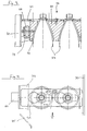
- Fig. 1
- the schematic side view of a machine for cleaning bottles
- Fig. 2
- the schematic plan view of the machine of FIG. 1st
- Fig. 3
- a vertical partial section through the endless conveyor for the bottles in the area of a bottle basket
- Fig. 4
- 3 shows the partial top view of the bottle basket according to FIG. 3.
Die Maschine nach Fig. 1 bis 4 ist zum Reinigen von Mehrweg-PET-Flaschen 37 - im Nachstehenden kurz Flaschen genannt - eingerichtet, die unterhalb des Flaschenkopfs einen vorstehenden Tragring besitzen. Die Maschine weist ein kasten- bzw. quaderförmiges Gehäuse 18 mit je zwei parallelen Stirn-, Seiten- und Boden- bzw. Deckflächen auf, das in herkömmlicher Weise aus fest miteinander verbundenen, teilweise lösbaren Platten aufgebaut und mittels mehreren Füßen auf dem Boden einer Abfüllanlage in horizontaler Ausrichtung aufgestellt ist.The machine according to FIGS. 1 to 4 is set up for cleaning reusable PET bottles 37 - called bottles below for short - which have a protruding support ring below the bottle head. The machine has a box-shaped or
Im Bereich der beiden Stirnseiten des Gehäuses 18 sind parallel zu diesen in einer senkrechten Ebene übereinander je zwei horizontale Wellen 23 bis 26 drehbar gelagert. Auf den beiden unteren, in gleicher Höhe liegenden Wellen 23 und 25 sind jeweils sechs Paare von unteren Umlenkrädern 20 und 21 in Form von Zahnrädern befestigt. Auf den auf gleicher Höhe liegenden oberen Wellen 24 und 26 sind sieben Paare von oberen Umlenkrädern 19 und 22 in Form von Zahnrädern befestigt. Die Umlenkräder sind in insgesamt sieben senkrechten, parallel zu den Längsseiten des Gehäuses 18 ausgerichteten und mit gleichem Abstand zueinander angeordneten Doppelebenen angeordnet. Die Doppelebenen und die zugehörigen Umlenkräder sind mit dem Index "a" bis "g" versehen. In der vordersten Doppelebene "g" sind im Höhenbereich zwischen den unteren Umlenkrädern 20, 21 und den oberen Umlenkrädern 19, 22 in der Mitte der Längsseite auf gleicher Höhe nebeneinander zwei zusätzliche Umlenkräder 27, 28 mit parallel zu den Wellen 23 bis 26 ausgerichteten Achsen frei drehbar gelagert. Zumindest die beiden an der gleichen Stirnseite des Gehäuses 18 angeordneten Wellen 23, 24 werden durch einen Getriebemotor 38 oder dgl. mit gleicher Drehzahl und gleichem Drehsinn synchron zueinander kontinuierlich angetrieben.In the area of the two end faces of the
Über die Umlenkräder-Paare ist ein Endlosförderer 17 für die Flaschen 37 geführt. Dieser weist zwei parallele, endlose Rollenketten 29 auf, deren Rollen im Bereich zwischen zwei Umlenkrädern auf horizontalen, geradlinigen Laufschienen 39 geführt sind. Die Laufschienen 39 sind entweder an den Längsseiten des Gehäuses 18 oder an im Inneren des Gehäuses 18 angeordneten Stützen 40 befestigt. Zwischen den beiden Rollenketten 29 sind quer zur Bewegungsrichtung in horizontaler Ausrichtung eine Vielzahl von Flaschenkörben 30 befestigt, die jeweils eine Reihe von vier Flaschen 37 aufnehmen.An
Wie die Fig. 3 und 4 zeigen, ist jeder Flaschenkorb 30 als balkenartiges Formteil mit vier parallelen, an den Flaschenhals angepaßten Flaschenzellen 32 ausgebildet. Der Flaschenkopf und der Flaschenrumpf ragen aus den Flaschenzellen 32 heraus. Im Bereich des Flaschenkopfs ist an der planen Stirnseite des Flaschenkorbs 30 ein Klemmorgan in Form einer Platte 31 in Längsrichtung zwischen zwei Endpositionen verschiebbar gelagert, z.B. mittels Bolzen 40 und Langlöchern 41. Die Platte ist mit vier schlüssellochartigen Öffnungen 33 versehen, deren größerer Bereich den Durchtritts eines Flaschenkopfs gestattet und deren kleinerer Bereich in etwa dem Durchmesser des Flaschenhalses unterhalb des Tragrings entspricht oder geringfügig größer ist als dieser. In der nicht gezeigten rechten Endposition der Platte 31 überdecken sich die größeren Bereiche der Öffnungen 33 mit der entsprechenden Öffnung der Flaschenzelle 32 für den Flaschenkopf. In dieser Position kann die Flasche 37 in die Flaschenzelle 32 hinein bzw. aus dieser herausgeführt werden. In der gezeigten linken Endposition, in der sich der kleinere Bereich der Öffnung 33 mit der Flaschenzelle 32 überdeckt, werden die Flaschen durch die Platte 31 unterhalb des Tragrings gehalten und können somit nicht aus den Flaschenzellen 32 heraus. Die Halterung ist relativ lose, damit die Reinigungslösung eindringen kann.3 and 4 show, each
Die Überführung der Platten 31 zwischen ihren beiden Endpositionen erfolgt durch ortsfeste, schräg zur Bewegungsrichtung verlaufende Kurvenstücke 34 und 35. Das eine Kurvenstück 35, welches die Platten 31 aus der gezeigten Klemmstellung in die nicht gezeigte Freigabestellung überführt, ist im Bereich der Flaschenabgabe 16 angeordnet. Das andere Kurvenstück 34, welches die Platten 31 aus der Freigabestellung in die Klemmstellung überführt, ist im Bereich der Flaschenaufgabe 1 angeordnet. Die Kurvenstücke 34, 35 greifen direkt an den Randflächen der entsprechend abgerundeten Platten 31 an. An diesem Randbereich greift auch eine ortsfeste Führung 36 an, die entlang des Umlaufbereichs des Endlosförderers 17 in den Behandlungsstationen angeordnet ist und die Platten 31 in der Klemmstellung fixiert. Zusätzliche Verriegelungselemente für die Platten 31 sind somit nicht erforderlich und der Aufbau der Flaschenkörbe 30 und ihrer Klemmorgane ist äußerst einfach und betriebssicher.The
An der vorderen Längsseite des Gehäuses 18 ist eine Flaschenaufgabe 1 und eine Flaschenabgabe 16 angeordnet. Die zu reinigenden Flaschen 37 werden durch ein horizontales Förderband 41, das kurz vor der Maschinenmitte endet, zugeführt und durch ein weiteres horizontales Förderband 42, das kurz vor der Maschinenmitte beginnt, abgeführt. Die beiden Förderbänder 41, 42 liegen innerhalb der vordersten Doppelebene "g", sind auf der gleichen Höhe angeordnet und werden mit der gleichen Geschwindigkeit wie der Endlosförderer 17 in Pfeilrichtung kontinuierlich angetrieben. Durch eine nicht gezeigte Einteilvorrichtung üblicher Bauart werden die Flaschen 37 in parallelen Vierergruppen auf dem Förderband 41 entsprechend der Anordnung der Flaschenzellen 32 in den Flaschenkörben 30 formiert, derart, daß jeweils eine Flaschenreihe im Bereich der Flaschenaufgabe 1 mit einem schräg von oben herangeführten Flaschenkorb 30 zusammentrifft. Dabei dringen die Flaschen mit ihrem Kopf- und Halsbereich in die Flaschenzellen 32 vollständig ein, bis der Flaschenkopf wieder aus der Flaschenzelle 32 herausragt. In diesem Bereich wird durch das ortsfeste Kurvenstück 34 die Platte 31 aus der Freigabeposition in die Klemmposition überführt. Umgekehrt werden im Bereich der Flaschenabgabe 16 die in der Klemmposition ankommenden Platten 31 durch das ortsfeste Kurvenstück 35 aus der Verriegelungsposition in die Freigabeposition überführt, so daß die Flaschen frei auf dem Förderband 42 zu stehen kommen. Anschließend wird der Endlosförderer mit den Flaschenkörben 30 schräg nach oben vom Förderband 42 weggeführt, so daß die Flaschen 37 nach unten aus den Flaschenzellen 32 austreten können.A bottle feed 1 and a
Der Endlosförderer 17 läuft innerhalb der Doppelebene "g" von der Unterseite des Umlenkrads 19g schräg auf das Förderband 41 zu, durchläuft einen kurzen horizontalen Bereich am Kurvenstück 34, umschlingt dann das zusätzliche Umlenkrad 28 und verläuft schräg nach oben zum Umlenkrad 19f. Von diesem läuft der Endlosförderer 17 senkrecht nach unten zum Umlenkrad 20f und weiter von dessen Unterseite innerhalb der Doppelebene "f" zu Unterseite des Umlenkrades 21f. Nachdem er dieses um 180 Grad umfahren hat läuft der Endlosförderer 17 von der Oberseite des Umlenkrads 21f schräg aus der Doppelebene "f" heraus in die Doppelebene "e" zur Oberseite des Umlenkrads 20e. Er umschlingt dieses und läuft von dessen Unterseite zur Unterseite des Umlenkrads 21e. In entsprechender Weise windet sich der Endlosförderer 17 weiter durch die Doppelebenen "d", "c", "b" bis in die Doppelebene "a". Dabei verläuft jeweils das untere Trum des Endlosförderers 17 innerhalb bzw. parallel zu einer Doppelebene, während das obere Trum schräg von einer Doppelebene zur anderen verläuft.The
Vom Umlenkrad 21a verläuft der Endlosförderer 17 senkrecht nach oben zum Umlenkrad 22a und von dessen Oberseite zur Oberseite des Umlenkrads 19a. Er umschlingt dieses um 180 Grad und verläuft von dessen Unterseite aus der Doppelebene "a" heraus schräg in die nächste Doppelebene "b" zur Unterseite des Umlenkrads 22b. Er umschlingt dieses um 180 Grad und verläuft von dessen Oberseite innerhalb der Doppelebene "b" zur Oberseite des Umlenkrads 19b. In entsprechender Weise windet sich der Endlosförderer durch die Ebenen "c", "d", "e" bis in die Ebene "f". Dabei verläuft jeweils das obere Trum des Endlosförderers 17 parallel bzw. innerhalb der Doppelebenen, wahrend das untere Trum schräg zur benachbarten Doppelebene weiterläuft. Von der Oberseite des Umlenkrads 22f verläuft der Endlosförderer schräg nach unten und schräg aus der Doppelebene "f" heraus in die Doppelebene "g" zur Oberseite des zusätzlichen Umlenkrads 27. Er umschlingt dieses und läuft dann von dessen Unterseite im Bereich des Kurvenstücks 35 horizontal innerhalb der Doppelebene "g" und dann schräg nach oben zur Unterseite des Umlenkrads 22g. Er umschlingt dieses und läuft dann von dessen Oberseite innerhalb der Doppelebene "g" zur Oberseite des Umlenkrads 19g.The
Durch die vorstehend beschriebene Führung des Endlosförderers 17 wird der Innenraum des Gehäuses 18 vollständig ausgenutzt und es wird neben einer sehr langen Behandlungsstrecke auch eine einfache Zu- und Abführung der Flaschen 37 durch die schräg nach unten bzw. schräg nach oben verlaufenden Bereiche innerhalb der Flaschenaufgabe 1 bzw. der Flaschenabgabe 16 ermöglicht. Wie die Fig. 2 zeigt, überdecken sich, von oben gesehen, die Bewegungsbahnen des Endlosförderers 17 im unteren, durch die unteren Umlenkräder 20, 21 definierten Bereich A und im oberen, durch die oberen Umlenkräder 19, 22 definierten Bereich B. Im unteren Bereich A schraubt sich der Endlosförderer nach Art einer Spirale in horizontaler Richtung von der Vorderseite des Gehäuses 18 weg, während er sich im oberen Bereich B nach Art einer Spirale zur Vorderseite des Gehäuses 18 hin schraubt. Dabei ergibt sich im Bereich A die durch den Pfeil X angegebene Querbewegung und im Bereich B die durch den Pfeil Y angegebene Querbewegung des Endlosförderers 17.By guiding the
Um eine Reinfektion der gereinigten Flaschen 37 zu verhindern, ist zwischen Flaschenaufgabe 1 und Flaschenabgabe 16 im Bereich zwischen den beiden zusätzlichen Umlenkrädern 28, 27 eine Trennwand 43 angeordnet. Außerdem ist zur einfachen Anpassung an unterschiedliche Flaschenhöhen sowohl die Lagerung des Umlenkrads 27 als auch die Lagerung des Umlenkrads 28 höhenverstellbar ausgeführt, jeweils zusammen mit einer nicht gezeigten kurzen horizontalen Führungsschiene für den horizontalen Umlaufbereich des Endlosförderers 17.In order to prevent reinfection of the cleaned
Die von der Flaschenaufgabe 1 kommenden Flaschen 37 werden gewendet und durchlaufen als erstes eine Einrichtung 2 zur Entleerung und Vorspritzung. Anschließend tauchen sie in das Reinigungslösungsbad 3 ein, das mit heißer Lauge gefüllt ist und den gesamten unteren Bereich A des Endlosförderers 17 mit den Doppelebenen "a" bis "f" umfaßt. Dort bleiben die Flaschen 37 ca. 7 Min. vollständig untergetaucht, wobei sich durch die Bewegung der Flaschen 37 eine starke Reinigungswirkung ergibt. Danach laufen die Flaschen bei 5 nach oben in den Bereich B, werden gewendet und bei 6 entleert. Danach durchlaufen sie eine Spritzung 7 mit Reinigungslösung und tauchen dann nach einem Austropfen bei 8 in ein erstes Wasserbad 9 ein. In ähnlicher Weise folgen weitere Spritzungen 10, 12 und 14 mit Wasser und Tauchbäder 11 und 13 mit Wasser. Bei 15 erfolgt dann ein letztes Austropfen der Flaschen, bevor sie zur Flaschenabgabe 16 gelangen.The
Im oberen Bereich B verläuft jeweils das obere Trum des Endlosförderers 17 innerhalb der entsprechenden Doppelebene.In the upper area B, the upper run of the
Dort sind die feststehenden oder auch oszillierend angetriebenen Spritzrohre der verschiedenen Spritzungen angeordnet. Die unteren Trume verlaufen jeweils schräg von einer Doppelebene zur anderen. Dort sind die entsprechend schräggestellten Tauchbäder angeordnet.The fixed or oscillating spray pipes of the different sprayings are arranged there. The lower dreams run diagonally from one double level to the other. The correspondingly inclined immersion baths are arranged there.
Claims (21)
Applications Claiming Priority (2)
| Application Number | Priority Date | Filing Date | Title |
|---|---|---|---|
| DE9110492U | 1991-08-24 | ||
| DE9110492U DE9110492U1 (en) | 1991-08-24 | 1991-08-24 |
Publications (2)
| Publication Number | Publication Date |
|---|---|
| EP0529387A1 true EP0529387A1 (en) | 1993-03-03 |
| EP0529387B1 EP0529387B1 (en) | 1995-12-06 |
Family
ID=6870575
Family Applications (1)
| Application Number | Title | Priority Date | Filing Date |
|---|---|---|---|
| EP92113599A Expired - Lifetime EP0529387B1 (en) | 1991-08-24 | 1992-08-10 | Machine for cleaning bottles and the like |
Country Status (6)
| Country | Link |
|---|---|
| US (1) | US5285801A (en) |
| EP (1) | EP0529387B1 (en) |
| JP (1) | JPH0815590B2 (en) |
| BR (1) | BR9203286A (en) |
| DE (2) | DE9110492U1 (en) |
| ES (1) | ES2082297T3 (en) |
Cited By (4)
| Publication number | Priority date | Publication date | Assignee | Title |
|---|---|---|---|---|
| US6185910B1 (en) | 1997-07-24 | 2001-02-13 | Krones Ag | Method and an apparatus for high-purity bottling of beverages |
| WO2003082488A1 (en) * | 2002-03-28 | 2003-10-09 | Krones Ag | Method and device for the treatment of plastic bottles |
| EP2218523A1 (en) | 2009-02-12 | 2010-08-18 | Krones AG | Bottle cleaning machine |
| DE102017126266A1 (en) | 2017-11-09 | 2019-05-09 | Krones Ag | Apparatus and method for cleaning containers |
Families Citing this family (8)
| Publication number | Priority date | Publication date | Assignee | Title |
|---|---|---|---|---|
| DE4326601A1 (en) * | 1993-08-07 | 1995-02-09 | Kronseder Maschf Krones | Method and device for sterile bottling of beverages |
| DE4412441C2 (en) * | 1994-04-12 | 1996-03-14 | Ortmann & Herbst Masch Gmbh | Washing machine for plastic bottles with a neck collar |
| DE19644742A1 (en) * | 1996-10-28 | 1998-04-30 | Diversey Gmbh | Process for the machine cleaning of reusable beverage packaging |
| DE19733582B4 (en) * | 1997-08-02 | 2005-02-17 | Krones Ag | Method and device for treating bottles or the like in a liquid bath |
| US20020085971A1 (en) * | 2001-01-03 | 2002-07-04 | Raniwala Subodh K. | Bottle sterilizing system and method |
| ITRM20020110A1 (en) * | 2002-02-28 | 2003-08-28 | Sipa Spa | CONTAINER PAINTING DEVICE AND METHOD. |
| DE102011080746A1 (en) * | 2011-08-10 | 2013-02-14 | Robert Bosch Gmbh | Device for holding and positioning of pharmaceutical products designed as tablets, hard gelatin capsules or the like in a packaging installation |
| CN109415166B (en) | 2016-06-22 | 2021-08-31 | 康宁股份有限公司 | Apparatus for holding and conveying glass articles |
Citations (3)
| Publication number | Priority date | Publication date | Assignee | Title |
|---|---|---|---|---|
| DE511728C (en) * | 1926-12-19 | 1930-11-03 | Oswald Waentig | Cleaning device for bottles of all kinds |
| FR1114257A (en) * | 1949-10-17 | 1956-04-10 | Bottle washing machine | |
| GB2005641A (en) * | 1977-10-10 | 1979-04-25 | Stork Apparatenbouw Bv | A machine for cleaning bottles |
Family Cites Families (11)
| Publication number | Priority date | Publication date | Assignee | Title |
|---|---|---|---|---|
| US1746644A (en) * | 1928-06-22 | 1930-02-11 | Young Brothers Company | Sinuous conveyer |
| US1910241A (en) * | 1932-04-21 | 1933-05-23 | Frank D Chapman | Exhaust box |
| US2011786A (en) * | 1934-03-22 | 1935-08-20 | Walker Charles Widmer | Milk bottle washing machine |
| US2094398A (en) * | 1936-08-31 | 1937-09-28 | John R Dostal | Bottle washing machine |
| US2516998A (en) * | 1944-02-15 | 1950-08-01 | Hartford Empire Co | Bottle delabeling apparatus |
| US2834453A (en) * | 1955-01-27 | 1958-05-13 | Hendrikus W M Domension | Bottle conveying device |
| SU444707A1 (en) * | 1972-04-24 | 1974-09-30 | Государственный Проектный Институт Строительного Машиностроения | Multi-blond overhead conveyor |
| SU549417A1 (en) * | 1975-03-04 | 1977-03-05 | Управление Пищевой Промышленности Краснодарского Крайисполкома | Installation for washing cans |
| SU810607A1 (en) * | 1979-04-24 | 1981-03-07 | Производственно-Техническое Объе-Динение Рыбной Промышленности Ce-Верного Бассейна "Севтехрыбпром"Всесоюзного Рыбопромышленного Об'-Единения "Севрыба" | Device for washing filled cylindrical cans |
| JPS6379657A (en) * | 1986-09-24 | 1988-04-09 | 四国化工機株式会社 | Container sterilizing apparatus |
| US5010808A (en) * | 1990-01-23 | 1991-04-30 | Apv Baker Inc. | Spiral conveyor oven |
-
1991
- 1991-08-24 DE DE9110492U patent/DE9110492U1/de not_active Expired - Lifetime
-
1992
- 1992-08-10 ES ES92113599T patent/ES2082297T3/en not_active Expired - Lifetime
- 1992-08-10 EP EP92113599A patent/EP0529387B1/en not_active Expired - Lifetime
- 1992-08-10 DE DE59204570T patent/DE59204570D1/en not_active Expired - Lifetime
- 1992-08-21 US US07/933,474 patent/US5285801A/en not_active Expired - Lifetime
- 1992-08-21 JP JP4222924A patent/JPH0815590B2/en not_active Expired - Lifetime
- 1992-08-21 BR BR929203286A patent/BR9203286A/en not_active IP Right Cessation
Patent Citations (3)
| Publication number | Priority date | Publication date | Assignee | Title |
|---|---|---|---|---|
| DE511728C (en) * | 1926-12-19 | 1930-11-03 | Oswald Waentig | Cleaning device for bottles of all kinds |
| FR1114257A (en) * | 1949-10-17 | 1956-04-10 | Bottle washing machine | |
| GB2005641A (en) * | 1977-10-10 | 1979-04-25 | Stork Apparatenbouw Bv | A machine for cleaning bottles |
Cited By (5)
| Publication number | Priority date | Publication date | Assignee | Title |
|---|---|---|---|---|
| US6185910B1 (en) | 1997-07-24 | 2001-02-13 | Krones Ag | Method and an apparatus for high-purity bottling of beverages |
| WO2003082488A1 (en) * | 2002-03-28 | 2003-10-09 | Krones Ag | Method and device for the treatment of plastic bottles |
| EP2218523A1 (en) | 2009-02-12 | 2010-08-18 | Krones AG | Bottle cleaning machine |
| US8640719B2 (en) | 2009-02-12 | 2014-02-04 | Krones Ag | Bottle cleaning machine |
| DE102017126266A1 (en) | 2017-11-09 | 2019-05-09 | Krones Ag | Apparatus and method for cleaning containers |
Also Published As
| Publication number | Publication date |
|---|---|
| BR9203286A (en) | 1993-04-06 |
| JPH0751649A (en) | 1995-02-28 |
| DE59204570D1 (en) | 1996-01-18 |
| US5285801A (en) | 1994-02-15 |
| ES2082297T3 (en) | 1996-03-16 |
| EP0529387B1 (en) | 1995-12-06 |
| DE9110492U1 (en) | 1992-09-24 |
| JPH0815590B2 (en) | 1996-02-21 |
Similar Documents
| Publication | Publication Date | Title |
|---|---|---|
| DE3301525C2 (en) | ||
| EP0529387B1 (en) | Machine for cleaning bottles and the like | |
| WO2006087109A1 (en) | Pre-table system | |
| DE60200934T2 (en) | Device for preparing bottles to be labeled in a bottling plant | |
| DE1456895A1 (en) | Treatment device for tin cans | |
| DE2432987C2 (en) | Device for treating containers | |
| DE1782313B2 (en) | DEVICE FOR CLEANING SUGAR BEET TESTS | |
| EP0244865B1 (en) | Apparatus for cleaning cans | |
| DE19650944C1 (en) | Bottle cleaning machine in double end design | |
| DE3436865A1 (en) | Device for cleaning bottle crates or the like | |
| DE19502272C2 (en) | Bottle cleaning machine in one-end construction | |
| DE10331982B4 (en) | Plant for cleaning boxes, in particular crates | |
| DE3611494C2 (en) | ||
| EP0501302A1 (en) | Device for treating bottles and similar upside down | |
| DE19733582B4 (en) | Method and device for treating bottles or the like in a liquid bath | |
| DE4008636A1 (en) | SPRAYING STATION | |
| DE8435932U1 (en) | DEVICE FOR WASHING BOTTLE BOXES | |
| DE2119267A1 (en) | Crate washing machine | |
| DE1817484A1 (en) | Wall part | |
| DE3345374A1 (en) | DEVICE FOR CLEANING TUB-SHAPED CONTAINERS | |
| DE2844126A1 (en) | MACHINE FOR CLEANING BOTTLES | |
| DE3223005A1 (en) | Apparatus for cleaning bottles | |
| DE3341852A1 (en) | Bottle cleaning machine | |
| DE504250C (en) | Washing and post-treatment machine for rayon | |
| DE102004015097A1 (en) | Cleaning plant for bottle crates has treatment zones including one immersion bath and one for spraying crates with cleaning fluid |
Legal Events
| Date | Code | Title | Description |
|---|---|---|---|
| PUAI | Public reference made under article 153(3) epc to a published international application that has entered the european phase |
Free format text: ORIGINAL CODE: 0009012 |
|
| AK | Designated contracting states |
Kind code of ref document: A1 Designated state(s): BE DE ES FR GB IT NL |
|
| 17P | Request for examination filed |
Effective date: 19930115 |
|
| 17Q | First examination report despatched |
Effective date: 19940421 |
|
| GRAA | (expected) grant |
Free format text: ORIGINAL CODE: 0009210 |
|
| ITF | It: translation for a ep patent filed |
Owner name: PATRITO BREVETTI |
|
| AK | Designated contracting states |
Kind code of ref document: B1 Designated state(s): BE DE ES FR GB IT NL |
|
| ET | Fr: translation filed | ||
| REF | Corresponds to: |
Ref document number: 59204570 Country of ref document: DE Date of ref document: 19960118 |
|
| REG | Reference to a national code |
Ref country code: ES Ref legal event code: FG2A Ref document number: 2082297 Country of ref document: ES Kind code of ref document: T3 |
|
| GBT | Gb: translation of ep patent filed (gb section 77(6)(a)/1977) |
Effective date: 19960422 |
|
| PLBE | No opposition filed within time limit |
Free format text: ORIGINAL CODE: 0009261 |
|
| STAA | Information on the status of an ep patent application or granted ep patent |
Free format text: STATUS: NO OPPOSITION FILED WITHIN TIME LIMIT |
|
| 26N | No opposition filed | ||
| REG | Reference to a national code |
Ref country code: GB Ref legal event code: IF02 |
|
| PGFP | Annual fee paid to national office [announced via postgrant information from national office to epo] |
Ref country code: BE Payment date: 20060816 Year of fee payment: 15 |
|
| BERE | Be: lapsed |
Owner name: *KRONES A.G. HERMANN KRONSEDER MASCHINENFABRIK Effective date: 20070831 |
|
| PG25 | Lapsed in a contracting state [announced via postgrant information from national office to epo] |
Ref country code: BE Free format text: LAPSE BECAUSE OF NON-PAYMENT OF DUE FEES Effective date: 20070831 |
|
| PGFP | Annual fee paid to national office [announced via postgrant information from national office to epo] |
Ref country code: FR Payment date: 20090814 Year of fee payment: 18 Ref country code: ES Payment date: 20090902 Year of fee payment: 18 |
|
| PGFP | Annual fee paid to national office [announced via postgrant information from national office to epo] |
Ref country code: NL Payment date: 20090803 Year of fee payment: 18 Ref country code: GB Payment date: 20090805 Year of fee payment: 18 |
|
| REG | Reference to a national code |
Ref country code: NL Ref legal event code: V1 Effective date: 20110301 |
|
| GBPC | Gb: european patent ceased through non-payment of renewal fee |
Effective date: 20100810 |
|
| REG | Reference to a national code |
Ref country code: FR Ref legal event code: ST Effective date: 20110502 |
|
| PG25 | Lapsed in a contracting state [announced via postgrant information from national office to epo] |
Ref country code: NL Free format text: LAPSE BECAUSE OF NON-PAYMENT OF DUE FEES Effective date: 20110301 |
|
| PG25 | Lapsed in a contracting state [announced via postgrant information from national office to epo] |
Ref country code: FR Free format text: LAPSE BECAUSE OF NON-PAYMENT OF DUE FEES Effective date: 20100831 |
|
| PG25 | Lapsed in a contracting state [announced via postgrant information from national office to epo] |
Ref country code: GB Free format text: LAPSE BECAUSE OF NON-PAYMENT OF DUE FEES Effective date: 20100810 |
|
| REG | Reference to a national code |
Ref country code: ES Ref legal event code: FD2A Effective date: 20111019 |
|
| PG25 | Lapsed in a contracting state [announced via postgrant information from national office to epo] |
Ref country code: ES Free format text: LAPSE BECAUSE OF NON-PAYMENT OF DUE FEES Effective date: 20100811 |
|
| PGFP | Annual fee paid to national office [announced via postgrant information from national office to epo] |
Ref country code: DE Payment date: 20110803 Year of fee payment: 20 |
|
| PGFP | Annual fee paid to national office [announced via postgrant information from national office to epo] |
Ref country code: IT Payment date: 20110811 Year of fee payment: 20 |
|
| REG | Reference to a national code |
Ref country code: DE Ref legal event code: R071 Ref document number: 59204570 Country of ref document: DE |
|
| REG | Reference to a national code |
Ref country code: DE Ref legal event code: R071 Ref document number: 59204570 Country of ref document: DE |
|
| PG25 | Lapsed in a contracting state [announced via postgrant information from national office to epo] |
Ref country code: DE Free format text: LAPSE BECAUSE OF EXPIRATION OF PROTECTION Effective date: 20120811 |