EP0244785B1 - Dossier pour sièges de véhicules notamment pour sièges arrières de véhicules automobiles - Google Patents
Dossier pour sièges de véhicules notamment pour sièges arrières de véhicules automobiles Download PDFInfo
- Publication number
- EP0244785B1 EP0244785B1 EP87106350A EP87106350A EP0244785B1 EP 0244785 B1 EP0244785 B1 EP 0244785B1 EP 87106350 A EP87106350 A EP 87106350A EP 87106350 A EP87106350 A EP 87106350A EP 0244785 B1 EP0244785 B1 EP 0244785B1
- Authority
- EP
- European Patent Office
- Prior art keywords
- back rest
- rotary knob
- support part
- spigot
- recess
- Prior art date
- Legal status (The legal status is an assumption and is not a legal conclusion. Google has not performed a legal analysis and makes no representation as to the accuracy of the status listed.)
- Expired - Lifetime
Links
- 239000002184 metal Substances 0.000 claims description 8
- 229920003023 plastic Polymers 0.000 claims description 6
- 239000004033 plastic Substances 0.000 claims description 6
- 238000002347 injection Methods 0.000 claims description 3
- 239000007924 injection Substances 0.000 claims description 3
- 239000000463 material Substances 0.000 claims description 3
- 238000010276 construction Methods 0.000 claims description 2
- 238000003466 welding Methods 0.000 claims description 2
- 238000001746 injection moulding Methods 0.000 claims 1
- 238000004519 manufacturing process Methods 0.000 description 3
- 239000004753 textile Substances 0.000 description 2
- 238000009434 installation Methods 0.000 description 1
- 230000003993 interaction Effects 0.000 description 1
- 230000003287 optical effect Effects 0.000 description 1
Images

Classifications
-
- B—PERFORMING OPERATIONS; TRANSPORTING
- B60—VEHICLES IN GENERAL
- B60N—SEATS SPECIALLY ADAPTED FOR VEHICLES; VEHICLE PASSENGER ACCOMMODATION NOT OTHERWISE PROVIDED FOR
- B60N2/00—Seats specially adapted for vehicles; Arrangement or mounting of seats in vehicles
- B60N2/24—Seats specially adapted for vehicles; Arrangement or mounting of seats in vehicles for particular purposes or particular vehicles
- B60N2/32—Seats specially adapted for vehicles; Arrangement or mounting of seats in vehicles for particular purposes or particular vehicles convertible for other use
- B60N2/36—Seats specially adapted for vehicles; Arrangement or mounting of seats in vehicles for particular purposes or particular vehicles convertible for other use into a loading platform
- B60N2/366—Seats specially adapted for vehicles; Arrangement or mounting of seats in vehicles for particular purposes or particular vehicles convertible for other use into a loading platform characterised by the locking device
-
- B—PERFORMING OPERATIONS; TRANSPORTING
- B60—VEHICLES IN GENERAL
- B60R—VEHICLES, VEHICLE FITTINGS, OR VEHICLE PARTS, NOT OTHERWISE PROVIDED FOR
- B60R5/00—Compartments within vehicle body primarily intended or sufficiently spacious for trunks, suit-cases, or the like
- B60R5/006—Compartments within vehicle body primarily intended or sufficiently spacious for trunks, suit-cases, or the like stowing or holding means for elongated articles, e.g. skis inside vehicles
-
- B—PERFORMING OPERATIONS; TRANSPORTING
- B60—VEHICLES IN GENERAL
- B60N—SEATS SPECIALLY ADAPTED FOR VEHICLES; VEHICLE PASSENGER ACCOMMODATION NOT OTHERWISE PROVIDED FOR
- B60N2205/00—General mechanical or structural details
- B60N2205/30—Seat or seat parts characterised by comprising plural parts or pieces
- B60N2205/35—Seat, bench or back-rests being split laterally in two or more parts
Definitions
- the invention relates to a backrest for vehicle seats, in particular for the rear seats of motor vehicles, with a center armrest which can be folded out to the front and with a backrest support part which is arranged behind the center armrest and can be locked on the body side and which - after creating a loading hatch in the region of the center armrest - after loosening the body-side lock can also be folded out towards the front.
- the object of the present invention is to provide an effective and reliable, releasable backrest lock with simple means.
- the object is achieved in a backrest of the type mentioned in that a pin part is used to lock the backrest support part, on the side counter-bearings are arranged and the body-side behind the backrest support part is non-detachably fixed, and that the counter bearing having free end of the pin part in the folded-back state of the backrest support part penetrates a recess in the backrest support part and that a knob can be placed on the pin part from the front of the backrest support part, which has a sleeve part with a central recess, on the inner wall of which lateral Detents are arranged, which cooperate with the counter bearings of the pin part when the rotary knob is actuated in the manner of a bayonet lock.
- the lock according to the invention is characterized by low costs, easy and simple assembly and by a simple and safe function.
- a particular advantage is that the locking according to the invention allows large manufacturing tolerances of ⁇ 3 mm, caused by the installation of the backrest support part and welding inaccuracies on the body, to be compensated for without problems.
- the lock according to the invention also has advantages from an optical point of view.
- pin part and the rotary knob are formed as plastic injection-molded parts and the counter bearings and notches and possibly other elements of the pin part and the rotary knob are each integrally formed.
- 10 denotes the seat part of a motor vehicle rear seat, which consists of a seat frame 11 and a seat cushion 12 arranged thereon (shown partially cut away).
- the backrest of the vehicle seat 10 is designated by 13 overall. It has three supporting sheet metal parts 14, 15 and 16, which - individually or jointly pivotable forward - are attached to the body 17 (FIG. 2).
- a backrest cushion is arranged on each of the two outer sheet metal parts 14 and 16, one of which is shown in FIG. 1 and numbered 18. It is therefore a back seat backrest with backrest parts which can be pivoted individually forward. 1, however, the backrest 13 is shown in the folded-back position.
- a center armrest 19 is pivotably and removably arranged in the region of the middle backrest support part 15. Hinge parts 20, 21 and 22 serve this purpose.
- the pivot axis of the center armrest 19 is 20.
- the center armrest 19 is sunk in a recess left between the backrest cushions. Here it rests on the backrest support part 15.
- the middle backrest support part 15 (as well as the two other sheet metal parts 14 and 16 of the backrest 13) can be folded forward individually.
- a connection to the trunk 23 (FIG. 2) is obtained between the two backrest cushions 18, which connection can be used as a loading hatch for bulky objects.
- the backrest support part 15, as already mentioned above is locked on the body side so that no unintentional automatic pivoting of the backrest support part 15 or the armrest 19 can take place during operation of the vehicle.
- the lock initially has a pin part 24, which is sleeve-like and accordingly has an inner axial recess 25.
- the recess 25 of the pin part 24 interacts with a metallic retaining bolt 26 (FIG. 2), which - as shown in FIG. 2 - is welded to the metal frame 27 of the parcel shelf.
- the metallic retaining bolt 26 has a thread in a known and therefore not shown manner and - at its free end - a knurling.
- the pin part 24 If the pin part 24 is now pressed onto the metal retaining pin 26, the measures described result in an inseparable fixation of the pin part 24 on the retaining pin 26, both in the axial and in the direction of rotation.
- the metal retaining bolt 26 engaging in the recess 25 of the pin part 24 is omitted.
- the pin part 24 has a flange-like collar 28 with which it comes to rest on a carpet cover 29 of the rear shelf 27 in the position mounted on the retaining bolt 26.
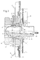
- Fig. 3 also reveals that the backrest support member 15 is covered on its back with a textile material 30 which has a circular recess 31.
- a locking ring 32 is inserted into the recess 31.
- the securing ring 32 has a plate 33 which is bent forward towards the plate and with which it is supported on the textile cover 30 of the backrest support part 15.
- the securing ring 32 has a recess 34 which is concentric with the recess 31 and has a circumferential collar 35 which is integrally formed on it.
- the locking ring 32 or its central recess 34 and the collar 35 cooperate with a rotary knob designated overall by 36 in a manner shown in FIG. 3.
- the rotary knob 36 consists in particular of a manually operable grip element 37, which forms a shoulder at 38, and a sleeve part 39, which cooperates or is connected to the locking ring 32 in the manner described below.
- a manually operable grip element 37 which forms a shoulder at 38
- a sleeve part 39 which cooperates or is connected to the locking ring 32 in the manner described below.
- several notches 40 are formed on the front free end of the sleeve part 39, on the circumference thereof, which engage behind the collar 35 of the securing ring 32 in the mounting position shown in FIG. 3.
- the knob 36 remains thereby movable in the direction of rotation, but is non-displaceably and non-releasably fixed in the axial direction with respect to the locking ring 32 and thus also with respect to the backrest support part 15.
- the catches 40 have bevels 41 which interact with a corresponding chamfer 42 on the locking ring 32.
- the mounting position of the rotary knob 36 shown in FIG. 3 is further determined by a slide ring 43 which, like the locking ring 32, has an edge 44 which is bent like a plate in the direction of the backrest support part 15.
- the slide ring 43 also has a central recess 45 which is penetrated by the sleeve part 39 of the rotary knob 36.
- the sleeve part 39 of the rotary knob 36 also extends through a circular recess 46 in the backrest support part 15.
- the rotary knob 36 serves primarily as a locking counterpart to the pin part 24 already mentioned and described. As FIG. 3 clearly shows, it projects the pin part 24 with its front free end into a continuous cylindrical recess 47 of the rotary knob 36. This position characterizes the locking position between the pin part 24 and the rotary knob 36.
- two cam-shaped counter bearings 48 are integrally formed on the side of the pin part at two diametrically opposite points.
- On the inner wall of the rotary knob 36 within the recess 47 of the same - two diametrically opposite points 49 are integrally formed, which cooperate with the counter bearings 48 of the pin part 24.
- the notches 49 which are also cam-shaped, engage behind the cam-shaped counter bearings 48 of the pin part 24 in the locking position shown in FIG. 3, so that the pin part 24 can no longer be moved out of the rotary knob 36 in the axial direction (arrow 50). Conversely, this means, since the Knob 36 - as described above - is connected to the backrest support member 15 that the backrest support member 15 is locked in its pivoted-back position with respect to the vehicle body.
Landscapes
- Engineering & Computer Science (AREA)
- Mechanical Engineering (AREA)
- Aviation & Aerospace Engineering (AREA)
- Transportation (AREA)
- Seats For Vehicles (AREA)
- Chairs For Special Purposes, Such As Reclining Chairs (AREA)
Claims (14)
- Dossier (13) pour sièges (10) de véhicules automobiles, en particulier pour les sièges arrières de véhicules automobiles, comportant un accoudoir central (19) rabattable vers l'avant et un élément porteur de dossier (15) disposé derrière l'accoudoir central et verrouillable sur la carrosserie qui - afin de créer une trappe de chargement dans la région de l'accoudoir central - peut être également rabattu vers l'avant après avoir libéré le verrouillage sur la carrosserie, caractérisé en ce qu'un têton (24) qui comporte latéralement de butées (48) et qui est monté de manière permanente sur la carrosserie (en 26, 27) derrière l'élément porteur de dossier (15), sert au verrouillage de l'élément porteur de dossier (15), et en ce que l'extrémité libre du têton (24) portant les butées (48) traverse, en position rabattue vers l'arrière de l'élément porteur de dossier (15), un évidement (31, 46) dans l'élément porteur de dossier (15), et en ce qu'un bouton tournant (36) peut être engagé sur le têton (24), à partir de la face avant de l'élément porteur de dossier (15), lequel bouton tournant présente une partie en manchon (39) munie d'un évidement central (47) sur la paroi intérieure duquel sont disposées des saillies radiales (49) qui coopèrent à la manière d'une fermeture à baïonnette avec les butées (48) du têton (24) lors de l'actionnement du bouton tournant (36).
- Dossier selon la revendication 1, caractérisé en ce que deux butées (48) formant cames sont disposées latéralement sur le têton en des points diamétralement opposés et des saillies (49) formant également cames derrière lesquelles s'engagent, en position de verrouillage, les butées en forme de cames (48) du têton (24), sont disposées sur la paroi intérieure (47) du bouton tournant (36) - également en des points diamétralement opposés.
- Dossier selon la revendication 1 ou 2, caractérisé en ce que les butées (48) en forme de cames du têton (24) sont effilées à la manière d'une flèche en direction du bouton tournant (36) et les saillies en forme de cames (49) du bouton tournant (36) sont effilées à la manière d'une flèche en direction du têton (24).
- Dossier selon la revendication 1, 2 ou 3, caractérisé en ce que des butées (51) sont disposées sur l'extrémité de la paroi interne (47) du bouton tournant opposée aux saillies (49) afin de déterminer axialement la position de verrouillage du têton (24) et du bouton tournant (36).
- Dossier selon une ou plusieurs des revendications précédentes, caractérisé en ce que le têton (24) et le bouton tournant (36) sont réalisés sous forme d'éléments en matière plastique moulés par injection et les butées (48) et les saillies (49) et éventuellement d'autres éléments du têton et du bouton tournant sont réalisés d'une pièce chaque fois.
- Dossier selon une ou plusieurs des revendications précédentes, caractérisé en ce qu'une bague d'arêt (32) est disposée dans un évidement (31) de l'élément porteur de dossier (15, 30), laquelle bague prend appui par son bord (33) en forme de flasque sur la face arrière de l'élément porteur de dossier et est munie d'un évidement (34) concentrique à l'évidement (31, 46) de l'élément porteur de dossier (15), dans lequel pénètrent, à partir de la face avant, la partie en manchon (39) du bouton tournant (36) et - en position verrouillée - à partir de la face arrière, le têton (24) (figure 3).
- Dossier selon la revendication 6, caractérisé en ce que la partie en manchon (39) du bouton tournant (36) avec la bagure d'arrêt (32) est mobile en rotation, mais est montée par encliquetage dans la direction axiale de manière non démontable, sans possibilité de déplacement en translation.
- Dossier selon la revendication 6 ou 7, caractérisé en ce que la bague d'arrêt (32) est réalisée sous la forme d'une pièce en matière plastique moulée par injection et présente à l'intérieur de son évidement (34) - comme butée pour le positionnement axial du bouton tournant (36) - un collet (35) venu d'une pièce, et en ce que plusieurs saillies (40) en forme de cames munies de rampes d'entrée (41) sont formées sur l'extrémité libre de la partie en manchon (39) du bouton tournant, lesquelles saillies s'accrochent en position de montage du bouton tournant (36) derrière le collet (35).
- Dossier selon une ou plusieurs des revendication précédentes, caractérisé en ce qu'une rondelle de friction (43) qui est traversée par la partie en manchon (39) du bouton tournant (36) et sur laquelle la partie poignée (37) du bouton tournant (36) prend appui par un épaulement (38), est placée entre le bouton tournant (36) et l'élément porteur de dossier (15).
- Dossier selon la revendication 9, caractérisé en ce que la rondelle de friction (43) est également réalisée sous la forme d'un élément en matière plastique moulé par injection et en ce que le têton (24), le bouton tournant (36), la bague d'arrêt (32) et la rondelle de friction (43), ainsi que tous les éléments fonctionnels moulés d'une pièce, sont réalisés en un même matériau.
- Dossier selon une ou plusieurs des revendication 6 à 10, caractérisé en ce que les bords (33 ou 44) de la bague d'arrêt (32) d'une part et de la rondelle de friction (43) d'autre part sont recourbés en forme de cuvette en direction de l'élément porteur de dossier (15).
- Dossier selon une ou plusieurs des revendication précédentes, caractérisé en ce que le têton (24) est réalisé sous la forme d'un manchon et est emmanché de manière non démontable sur un goujon-support (26) métallique fixé de préférence par soudure sur la carrosserie (figure 2).
- Dossier selon la revendication 12, caractérisé en ce que le goujon-support (26) métallique présente un filetage - pour l'immobilisation dans la direction axiale du têton (24) monté dessus - et, à son extrémité libre, un moletage - pour l'immobilisation en rotation du têton (24) monté dessus -.
- Dossier selon une ou plusieurs des revendication précédentes, caractérisé en ce que le têton (24) pénètre par son extrémité arrière dans un évidement de la plage arrière (27, 29) et prend appui sur la face avant de la plage arrière par l'intermédiaire d'une collerette en forme de flasque (28) venue d'une pièce.
Applications Claiming Priority (2)
| Application Number | Priority Date | Filing Date | Title |
|---|---|---|---|
| DE3615262 | 1986-05-06 | ||
| DE19863615262 DE3615262A1 (de) | 1986-05-06 | 1986-05-06 | Rueckenlehne fuer fahrzeugsitze, insbesondere fuer hintersitze von kraftfahrzeugen |
Publications (3)
| Publication Number | Publication Date |
|---|---|
| EP0244785A2 EP0244785A2 (fr) | 1987-11-11 |
| EP0244785A3 EP0244785A3 (en) | 1989-11-29 |
| EP0244785B1 true EP0244785B1 (fr) | 1992-02-26 |
Family
ID=6300261
Family Applications (1)
| Application Number | Title | Priority Date | Filing Date |
|---|---|---|---|
| EP87106350A Expired - Lifetime EP0244785B1 (fr) | 1986-05-06 | 1987-05-02 | Dossier pour sièges de véhicules notamment pour sièges arrières de véhicules automobiles |
Country Status (3)
| Country | Link |
|---|---|
| US (1) | US4756569A (fr) |
| EP (1) | EP0244785B1 (fr) |
| DE (2) | DE3615262A1 (fr) |
Families Citing this family (12)
| Publication number | Priority date | Publication date | Assignee | Title |
|---|---|---|---|---|
| DE8712884U1 (de) * | 1987-09-24 | 1987-11-12 | R. Schmidt GmbH, 5940 Lennestadt | Abdeckung für eine Durchladeöffnung |
| US5454613A (en) * | 1993-09-29 | 1995-10-03 | Ab Volvo | Automatic locking device for an auxiliary seat |
| US5447360A (en) * | 1993-09-30 | 1995-09-05 | Hoover Universal, Inc. | Side impact seat back structure |
| US6073996A (en) * | 1997-12-31 | 2000-06-13 | Tachi-S Co., Ltd. | Structure of seat back with armrest and method for forming the same |
| US6065795A (en) * | 1998-01-02 | 2000-05-23 | Daimlerchrysler Corporation | Seating arrangement for a motor vehicle |
| FR2775638B1 (fr) | 1998-03-05 | 2001-05-25 | Aisin Seiki | Systeme de cadre pour siege |
| AT3804U1 (de) | 1999-05-27 | 2000-08-25 | Tcg Unitech Ag | Sitzlehne für ein kraftfahrzeug |
| US6213546B1 (en) | 1999-11-24 | 2001-04-10 | Johnson Controls Technology Company | Sliding actuation armrest |
| DE10153156B4 (de) * | 2001-10-27 | 2006-09-21 | Keiper Gmbh & Co.Kg | Polsterträger für einen Fahrzeugsitz |
| DE102007043703A1 (de) * | 2007-09-13 | 2009-03-19 | Volkswagen Ag | Hintersitz-Lehne mit einem Mittelarmlehnenmodul |
| US20100199571A1 (en) * | 2009-02-06 | 2010-08-12 | International Automotive Components Group North American, Inc. | Covered door panel having an aperture and method of manufacturing same |
| WO2014129087A1 (fr) * | 2013-02-22 | 2014-08-28 | 株式会社タチエス | Structure de fixation de revêtement de garniture pour siège de véhicule, et siège de véhicule |
Family Cites Families (7)
| Publication number | Priority date | Publication date | Assignee | Title |
|---|---|---|---|---|
| DE1849156U (de) * | 1962-01-08 | 1962-03-29 | Friedrich Hornung | Behaelteranordnung fuer die unterbringung von skiern in kraftwagen. |
| FR2146564A5 (fr) * | 1971-07-19 | 1973-03-02 | Peugeot & Renault | |
| FR2278537A1 (fr) * | 1973-11-07 | 1976-02-13 | Odry Jean Marie | Dispositif pour loger des skis ou objets de grande longueur a l'interieur d'un vehicule automobile |
| FR2407837A1 (fr) * | 1977-11-07 | 1979-06-01 | Honda Motor Co Ltd | Siege arriere pour voiture |
| DE2755326A1 (de) * | 1977-12-12 | 1979-06-13 | Crocoll | Vorrichtung zur unterbringung von skiern in einem pkw |
| DE3322511A1 (de) * | 1983-06-23 | 1985-01-10 | Adam Opel AG, 6090 Rüsselsheim | Mittelarmlehne fuer kraftfahrzeugsitze |
| JPS6136455U (ja) * | 1984-08-07 | 1986-03-06 | マツダ株式会社 | 自動車のリヤシ−トバツクロツク装置 |
-
1986
- 1986-05-06 DE DE19863615262 patent/DE3615262A1/de active Granted
-
1987
- 1987-05-02 EP EP87106350A patent/EP0244785B1/fr not_active Expired - Lifetime
- 1987-05-02 DE DE8787106350T patent/DE3776811D1/de not_active Expired - Lifetime
- 1987-05-06 US US07/047,248 patent/US4756569A/en not_active Expired - Fee Related
Also Published As
| Publication number | Publication date |
|---|---|
| DE3776811D1 (de) | 1992-04-02 |
| US4756569A (en) | 1988-07-12 |
| EP0244785A3 (en) | 1989-11-29 |
| DE3615262A1 (de) | 1987-11-12 |
| EP0244785A2 (fr) | 1987-11-11 |
| DE3615262C2 (fr) | 1989-03-30 |
Similar Documents
| Publication | Publication Date | Title |
|---|---|---|
| DE3923989C2 (de) | Rücksitzanordnung für ein Kraftfahrzeug | |
| DE102017206720B4 (de) | Fahrzeugkonsole mit einer verstellbaren Armauflage | |
| DE69302213T2 (de) | Armlehne für Kraftfahrzeugsitze | |
| DE2848268C2 (fr) | ||
| DE2937117A1 (de) | Verriegelungsvorrichtung fuer fahrzeugsitze | |
| DE3615262C2 (fr) | ||
| DE69500197T2 (de) | Fahrzeugsitzgleitschiene | |
| DE69501005T2 (de) | Lenkradschloss für Kraftfahrzeuge mit Sperrvorrichtung des Riegelverschlusses | |
| DE2328908A1 (de) | Gelenkbeschlag fuer sitze mit verstellbarer lehne, insbesondere kraftfahrzeugsitze | |
| EP0245733A2 (fr) | Dispositif pour le logement détachable d'accoudoirs pivotants de sièges notamment d'accoudoirs centraux de sièges arrières de véhicules automobiles | |
| DE3518751C1 (de) | Sonnenblende fuer Fahrzeuge | |
| DE3036559A1 (de) | Sitz, insbesondere vordersitz fuer personenkraftfahrzeuge | |
| DE2200262A1 (de) | Einstellvorrichtung fuer einen verstellbaren Sitz | |
| DE69406157T2 (de) | Fahrzeugsitz und dessen Anwendung bei einem Rücksitz | |
| DE3842705A1 (de) | Sonnenblende fuer fahrzeuge | |
| DE1949085C3 (de) | Fahrzeugsitz, insbesondere Kraftfahrzeugsitz | |
| EP0076933B1 (fr) | Verrouillage pour dossiers pivotants de sièges arrières de voitures | |
| DE3939453C2 (de) | Fahrzeugsitz mit einer Rücklehne | |
| DE2405725A1 (de) | Kopfstuetze fuer rueckenlehnen von fahrzeugsitzen | |
| DE102017100935A1 (de) | Verriegelungsmechanismus für einen Deckel eines Ablagefachs eines Kraftfahrzeugs | |
| DE4039692C2 (de) | Halterung für einen Kraftfahrzeugsitz | |
| DE2359488A1 (de) | Vorrichtung zur verstellung der sitzrueckenlehne bei einem kraftfahrzeug | |
| DE2441398A1 (de) | Einrichtung zum verriegeln und entriegeln insbesondere eines am fahrzeugaufbau eines kraftfahrzeuges angeordneten fahrzeugsitzes | |
| DE10028403B4 (de) | Verschluss, insbesondere zum Festlegen einer Rückenlehne eines Kraftfahrzeuges | |
| EP0002730B1 (fr) | Appui-tête, en particulier pour sièges de véhicules |
Legal Events
| Date | Code | Title | Description |
|---|---|---|---|
| PUAI | Public reference made under article 153(3) epc to a published international application that has entered the european phase |
Free format text: ORIGINAL CODE: 0009012 |
|
| AK | Designated contracting states |
Kind code of ref document: A2 Designated state(s): DE FR GB IT SE |
|
| PUAL | Search report despatched |
Free format text: ORIGINAL CODE: 0009013 |
|
| AK | Designated contracting states |
Kind code of ref document: A3 Designated state(s): DE FR GB IT SE |
|
| 17P | Request for examination filed |
Effective date: 19900509 |
|
| 17Q | First examination report despatched |
Effective date: 19910806 |
|
| GRAA | (expected) grant |
Free format text: ORIGINAL CODE: 0009210 |
|
| AK | Designated contracting states |
Kind code of ref document: B1 Designated state(s): DE FR GB IT SE |
|
| ITF | It: translation for a ep patent filed | ||
| REF | Corresponds to: |
Ref document number: 3776811 Country of ref document: DE Date of ref document: 19920402 |
|
| GBT | Gb: translation of ep patent filed (gb section 77(6)(a)/1977) | ||
| ET | Fr: translation filed | ||
| PLBE | No opposition filed within time limit |
Free format text: ORIGINAL CODE: 0009261 |
|
| STAA | Information on the status of an ep patent application or granted ep patent |
Free format text: STATUS: NO OPPOSITION FILED WITHIN TIME LIMIT |
|
| 26N | No opposition filed | ||
| ITTA | It: last paid annual fee | ||
| EAL | Se: european patent in force in sweden |
Ref document number: 87106350.9 |
|
| REG | Reference to a national code |
Ref country code: GB Ref legal event code: 746 Effective date: 19950329 |
|
| PGFP | Annual fee paid to national office [announced via postgrant information from national office to epo] |
Ref country code: SE Payment date: 19960429 Year of fee payment: 10 |
|
| PG25 | Lapsed in a contracting state [announced via postgrant information from national office to epo] |
Ref country code: SE Effective date: 19970503 |
|
| REG | Reference to a national code |
Ref country code: FR Ref legal event code: D6 |
|
| EUG | Se: european patent has lapsed |
Ref document number: 87106350.9 |
|
| REG | Reference to a national code |
Ref country code: GB Ref legal event code: IF02 |
|
| PG25 | Lapsed in a contracting state [announced via postgrant information from national office to epo] |
Ref country code: IT Free format text: LAPSE BECAUSE OF NON-PAYMENT OF DUE FEES;WARNING: LAPSES OF ITALIAN PATENTS WITH EFFECTIVE DATE BEFORE 2007 MAY HAVE OCCURRED AT ANY TIME BEFORE 2007. THE CORRECT EFFECTIVE DATE MAY BE DIFFERENT FROM THE ONE RECORDED. Effective date: 20050502 |
|
| PGFP | Annual fee paid to national office [announced via postgrant information from national office to epo] |
Ref country code: FR Payment date: 20060519 Year of fee payment: 20 Ref country code: DE Payment date: 20060519 Year of fee payment: 20 |
|
| PGFP | Annual fee paid to national office [announced via postgrant information from national office to epo] |
Ref country code: GB Payment date: 20060522 Year of fee payment: 20 |
|
| REG | Reference to a national code |
Ref country code: GB Ref legal event code: PE20 |
|
| PG25 | Lapsed in a contracting state [announced via postgrant information from national office to epo] |
Ref country code: GB Free format text: LAPSE BECAUSE OF EXPIRATION OF PROTECTION Effective date: 20070501 |