EP0244568A1 - Bogenförderer für bogenverarbeitende Maschinen - Google Patents
Bogenförderer für bogenverarbeitende Maschinen Download PDFInfo
- Publication number
- EP0244568A1 EP0244568A1 EP87101908A EP87101908A EP0244568A1 EP 0244568 A1 EP0244568 A1 EP 0244568A1 EP 87101908 A EP87101908 A EP 87101908A EP 87101908 A EP87101908 A EP 87101908A EP 0244568 A1 EP0244568 A1 EP 0244568A1
- Authority
- EP
- European Patent Office
- Prior art keywords
- sheet
- gripper
- toothed belt
- support body
- toothed
- Prior art date
- Legal status (The legal status is an assumption and is not a legal conclusion. Google has not performed a legal analysis and makes no representation as to the accuracy of the status listed.)
- Granted
Links
- 238000007639 printing Methods 0.000 description 33
- 230000006835 compression Effects 0.000 description 2
- 238000007906 compression Methods 0.000 description 2
- 230000004913 activation Effects 0.000 description 1
- 230000001154 acute effect Effects 0.000 description 1
- 230000001427 coherent effect Effects 0.000 description 1
- 238000010276 construction Methods 0.000 description 1
- 238000000034 method Methods 0.000 description 1
- 238000007645 offset printing Methods 0.000 description 1
- 230000002093 peripheral effect Effects 0.000 description 1
- 230000011514 reflex Effects 0.000 description 1
Images
Classifications
-
- B—PERFORMING OPERATIONS; TRANSPORTING
- B65—CONVEYING; PACKING; STORING; HANDLING THIN OR FILAMENTARY MATERIAL
- B65H—HANDLING THIN OR FILAMENTARY MATERIAL, e.g. SHEETS, WEBS, CABLES
- B65H29/00—Delivering or advancing articles from machines; Advancing articles to or into piles
- B65H29/003—Delivering or advancing articles from machines; Advancing articles to or into piles by grippers
-
- B—PERFORMING OPERATIONS; TRANSPORTING
- B65—CONVEYING; PACKING; STORING; HANDLING THIN OR FILAMENTARY MATERIAL
- B65H—HANDLING THIN OR FILAMENTARY MATERIAL, e.g. SHEETS, WEBS, CABLES
- B65H29/00—Delivering or advancing articles from machines; Advancing articles to or into piles
- B65H29/02—Delivering or advancing articles from machines; Advancing articles to or into piles by mechanical grippers engaging the leading edge only of the articles
- B65H29/04—Delivering or advancing articles from machines; Advancing articles to or into piles by mechanical grippers engaging the leading edge only of the articles the grippers being carried by endless chains or bands
- B65H29/042—Intermediate conveyors, e.g. transferring devices
-
- B—PERFORMING OPERATIONS; TRANSPORTING
- B65—CONVEYING; PACKING; STORING; HANDLING THIN OR FILAMENTARY MATERIAL
- B65H—HANDLING THIN OR FILAMENTARY MATERIAL, e.g. SHEETS, WEBS, CABLES
- B65H29/00—Delivering or advancing articles from machines; Advancing articles to or into piles
- B65H29/02—Delivering or advancing articles from machines; Advancing articles to or into piles by mechanical grippers engaging the leading edge only of the articles
- B65H29/04—Delivering or advancing articles from machines; Advancing articles to or into piles by mechanical grippers engaging the leading edge only of the articles the grippers being carried by endless chains or bands
- B65H29/045—Details of grippers
-
- B—PERFORMING OPERATIONS; TRANSPORTING
- B65—CONVEYING; PACKING; STORING; HANDLING THIN OR FILAMENTARY MATERIAL
- B65H—HANDLING THIN OR FILAMENTARY MATERIAL, e.g. SHEETS, WEBS, CABLES
- B65H5/00—Feeding articles separated from piles; Feeding articles to machines
- B65H5/08—Feeding articles separated from piles; Feeding articles to machines by grippers, e.g. suction grippers
- B65H5/085—Feeding articles separated from piles; Feeding articles to machines by grippers, e.g. suction grippers by combinations of endless conveyors and grippers
-
- B—PERFORMING OPERATIONS; TRANSPORTING
- B65—CONVEYING; PACKING; STORING; HANDLING THIN OR FILAMENTARY MATERIAL
- B65H—HANDLING THIN OR FILAMENTARY MATERIAL, e.g. SHEETS, WEBS, CABLES
- B65H2404/00—Parts for transporting or guiding the handled material
- B65H2404/20—Belts
- B65H2404/23—Belts with auxiliary handling means
- B65H2404/231—Belts with auxiliary handling means pocket or gripper type
Definitions
- the present invention relates to a sheet conveyor for sheet-processing machines, with a positive-locking, rotating feed means, which runs at least over two end deflection wheels and possibly also between intermediate support wheels and carries at least one sheet transport sports gripper on its top, which in the course of the circulation path is opened or closed.
- Such sheet conveyors are known in various variations in the prior art. Such devices are usually designed as chain conveyors, which often feed a sheet to the front mark of a printing press or the like.
- a disadvantage of such chain conveyors is that their structure with the help of chains means that they are relatively complex and therefore cost-intensive. The grabs are common even switched into the chain on a special component in the form of a gripper carriage, which also requires a not inconsiderable design effort.
- chain conveyors run only with a considerable noise and have a considerable mass, so that they are not or only partially usable with high-speed machines.
- the circumferential feed means is formed from a number of toothed belts running over appropriately shaped gears, in which a recess is provided at one or more points along the longitudinal extent, in which a support body carrying a gripper mechanism is detachably inserted that the gears are provided with circumferential recesses which correspond to the inwardly projecting parts of the support body / gripper mechanism speak, and that each gripper mechanism has an actuating lever which is actuated by a cam track when it runs up / down.
- This configuration of the sheet conveyor eliminates the disadvantages in the prior art in a particularly simple manner.
- toothed belts can be equipped at any point with a gripper mechanism which can be exchanged easily in the event of faults.
- the gripper mechanism of the sheet conveyor is actuated in a particularly advantageous manner in that the cam track for the actuating lever is part of the circumferential recesses of the gear or gears.
- the rotating grippers can be actuated particularly simply by running up or down one of the gearwheels, although it is not excluded that a separate (stationary) cam track is also provided for this purpose, especially when opening and / or closing the grippers at a different location than in the area of one of the support or deflection wheels. of the sheet conveyor is desired.
- the support body preferably passes through the toothed belt and rests with its support plate on the outside of the toothed belt, wherein it is clamped by at least two fastening pins which are located on the inside of the toothed belt and are pushed through the support body.
- the gripper mechanism has a hook-shaped gripper which lies in the clamping position on the support plate on the top of the toothed belt. Since the gripper can be pivoted in the direction of the toothed belt about an axis which is arranged at a distance from the toothed belt on its inside in the direction of advance of the toothed belt before the clamping point, the gripper moves in the same direction of rotation in relation to the toothed belt and in the opposite direction when it is closed Direction, that is, that even a sheet conveyed at the speed of the toothed belt can be gripped without problems.
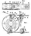
- two toothed belts (band 56) arranged parallel to the plane of the drawing are tensioned with the aid of two deflection rollers / gear wheels 52/54, of which, however, only one deflection roller 52 with one part in FIGS. 1 and 3 of the toothed belt 56 is shown.
- the belts 56 are designed as toothed belts and the associated deflection rollers 52/54 as corresponding toothed wheels. However, other forms of belts and deflection rollers are possible.
- the toothed belt 56 has a centrally arranged recess 55 at certain points along its longitudinal extent, into which the support body 60 with the gripper mechanism of the gripper 58 can be detachably inserted can.
- the support body 60 has an approximately T-shaped shape which is provided with a central recess and has a support arranged on the upper side of the toothed belt 56 plate 62 and two perpendicularly extending middle parts 64 which receive between them the gripper 58, which is penetrated at some distance from the support plate 62 or the toothed belt 56 by a hinge pin 66 which is supported in the two middle parts 64.
- the hook-shaped gripper 58 can thus be pivoted about the hinge pin 66 and the hook-shaped upper end of the gripper 58 which projects upwards over the support plate 62 above the top of the toothed belt 56 lies in the gripping position on the continuous part 63 of the support plate 62.
- a compression spring 68 is stretched between the support plate 62, 63 and a cam lever-like extension 70 of the hook-shaped gripper 58.
- the gripper 58 is normally pivoted into its clamping or gripping position, which it assumes in the entire course of the upper and lower run of the conveyor belt-like device and when walking around the deflection roller 54. Only when the gripper mechanism runs around the deflection roller / gear 52 does the gripper, as shown in FIG. 1, assume the open position by the cam-like extension 70 on the middle part 72 (which is larger than the deflection roller 54) (Cam track 61) runs up.
- both the deflecting roller 54 and the deflecting roller 52 have a nutenar in their central planes term recess 57, which corresponds approximately to the width of the lower part of the gripper mechanism ( Figure 2), but the groove-shaped recess in the deflection roller 52 is less deep than in the deflection roller 54, so that the gripper mechanism does not open the latter.
- the depth of the recess of the deflection roller 54 is indicated by dashed lines at 53 in FIG. 1 and also in FIG. 4.
- the gripping mechanism is easily detachably fastened to the toothed belt 56 by two locking pins 74 inserted through it. After removing these fastening pins 74, the gripper mechanism in FIG. 1 can simply be lifted up out of the recess in the toothed belt 56.
- These pins 75 are provided with a section of reduced diameter in the middle for better locking on the middle parts 64 of the T-shaped support body 60, as can be clearly seen in FIG. 2.
- the mounting pins 74 are preferably arranged so that they just - as shown - fill two adjacent depressions of the toothed belt. Accordingly, the teeth must then be left out at the corresponding points on the gear wheels 52, 54, as is indicated in the lower left part of FIG. 1. Such an arrangement of the mounting pins then requires also that the grippers on the toothed belt 5'6 are arranged just at a distance which corresponds to the pitch circle diameter of the gear wheels 52, 54 or a whole multiple thereof.
- these fastening pins 74 it is conceivable to give these fastening pins 74 a cross section which corresponds to an elevation or a tooth of the toothed belt and then to arrange the fastening pins in place of such a tooth. In this case, the position of the grippers on the toothed belt can be chosen practically freely.
- a gripper mechanism is shown which is just beginning to leave the deflection roller 52 and thus initiates the closing process of the gripper 58.
- the path of a printing sheet emerging, for example, from a printing press is indicated by an arrow 59.
- the printing sheet hits the plate 62/63 on the upper run of the toothed belt 56 at an acute angle. This allows any undulations on the front edge of the printing sheet to be compensated for, since the sheet thus aligns itself on the plate 62/63.
- the sheet to be clamped is placed on the toothed belt 56 or the support plate 62, 63 at such a speed that the differences limit speed is zero or approximately zero. Since the hinge pin 66 lies in the direction of movement of the toothed belt 56 in front of and below (in FIG.
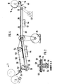
- FIG. 4 shows a basic illustration of a specific application of the sheet conveyor according to the invention, namely as a turning device 50 of a sheet conveying and turning device between two printing machines 3, 5 connected in tandem, of which only one or two printing rollers and one toward the other and oscillating suction roller for receiving and inserting a sheet to be printed are indicated by dash-dotted lines.
- an elongated belt conveyor 26 which consists of a number of endlessly arranged parallel to one another (and to the drawing plane) sen elastic bands 28 with a large coefficient of friction. These belts 28 are guided over two deflection rollers 30 and 32 at the beginning and end of the elongated belt conveyor. 26, further support rollers being distributed over the length of this conveyor as required.
- a support and drive roller is indicated in the middle at 38.
- the conveyor constructed in this way works in a very similar manner to a conventional conveyor belt, ie the printed sheets 36 deposited on its upper side by the turning device 50 and, if necessary, overlapping more or less are conveyed from the first printing press (left) to the second printing press (right) at a speed that depends on the circumstances of the individual case.
- the conveyor does not have to consist of individual endless belts 28 (approximately with a circular cross section) arranged parallel to one another, but it is readily conceivable that a coherent broad belt - for example with large holes in it or a network-like structure etc. - is also used .
- the belt conveyor 26 being able to be driven either centrally at the central support and drive roller 38 via the main motor 39, which simultaneously drives the two printing presses 3, 5 synchronously , or alternatively - as shown - by a separate, controllable drive motor 40, which acts, for example, on the deflection roller 32 at the end of the conveyor 26 and only drives the belt conveyor 26, while the main motor 39 drives the turning device 50 and the two printing presses 3, 5.
- suction chambers 42 are arranged just below the belt conveyor 26, which are subjected to a vacuum by suitable means.
- These suction chambers 42 have suction openings 44 pointing upwards, that is to say in the direction of the conveyor 26, so that there is a considerable air flow in the direction of the suction chambers, which then results in a more than over the large area of each printed sheet 36 deposited on the conveyor sufficient pressing force of the printed sheets against the conveyor having a significant coefficient of friction or its belts 28 leads.
- the printed sheets are thus fixed on the conveyor belt or belts of the conveyor and inevitably moved in the direction of the second printing press, where the front edge of each printing sheet finally abuts against a stop 46 serving as the front mark of the second printing press.
- the printed sheets are also aligned laterally, if this is necessary at all is.
- the sheet fed is fed in a known manner to the counter-pressure cylinder 18 of the second printing press by a reciprocating suction roll 14.
- a test device for example in the form of a reflex head 47, is provided in the area of the abovementioned stop 46 (front mark of the second printing press). On the one hand, it checks the correct entry of the sheets into the machine 5 in terms of time and distance, and on the other hand it controls the activation of the offset cylinder 20 of the machine 5 if a sheet is available at the time of the query.
- the printing sheet running out of the first printing machine 3 is guided straight to the beginning of the upper run of the turning device 50, in such a way that the leading edge of the printing sheet is below the gripper 58 of the turning device which closes at this point is given.
- the turning device runs at a peripheral speed which corresponds exactly to the output speed of the printing sheet from the first printing machine 3, so that the entire sheet is pulled off the printing machine and - without the gripper 58 opening - is guided around the deflection roller 54 of the turning device.
- the upper side of the printing sheet running out of the printing press is turned downward, since the printed side of the printing sheet points downward, ie towards the conveyor 26, after reaching the lower run of the turning device.
- this gripper 58 attached to the toothed belt 56 of the turning device hits the deflection roller 52 at the end of the lower run (located in the direction of rotation of the belt)
- this gripper opens and releases the front edge of the printing sheet, which now has the previously generated print image on the lower, ie the side facing the conveyor 26.
- the leading edge of the thus released, turned printing sheet then runs against a stop 51 at the end of the gap which is formed by the upper run of the belt conveyor 26 and the lower run of the turning device 50.
- the printed sheet is stopped and drawn against the belt conveyor 26 by the suction air generated by the suction chambers 42.
Landscapes
- Engineering & Computer Science (AREA)
- Mechanical Engineering (AREA)
- Discharge By Other Means (AREA)
- Feeding Of Articles By Means Other Than Belts Or Rollers (AREA)
- Delivering By Means Of Belts And Rollers (AREA)
- Catching Or Destruction (AREA)
- Processing Of Meat And Fish (AREA)
- Turning (AREA)
- Physical Vapour Deposition (AREA)
- Intermediate Stations On Conveyors (AREA)
Abstract
Description
- Die vorliegende Erfindung betrifft einen Bogen-Förderer für bogenverarbeitende Maschinen, mit einem formschlüssig angetriebenen, umlaufenden Vorschubmittel, welches mindestens über zwei endständige Umlenkräder und gegebenenfalls auch über dazwischen angeordnete Stützräder läuft und an seiner Oberseite mindestens einen Bogentran-sportgreifer trägt, der im Verlaufe des Umlaufweges geöffnet bzw. geschlossen wird.
- Derartige Bogenförderer sind in verschiedenen Variationen im Stand der Technik bekannt. Gewöhnlich sind derartige Einrichtungen als Kettenförderer ausgebildet, die häufig einen Bogen an die Vordermarke einer Druckmaschine oder dergleichen heranführen. Ein Nachteil bei derartigen Kettenförderern besteht darin, daß sie durch ihren Aufbau mit Hilfe von Ketten relativ aufwendig und daher kostenintensiv sind. Häufig werden die Greifer sogar an einem besonderen Bauteil in Form eines Greiferwagens in die Kette eingeschaltet, was ebenfalls einen nicht unerheblichen konstruktiven Aufwand erfordert. Außerdem laufen Kettenförderer nur mit einer erheblichen Geräuschentwicklung und weisen eine beachtliche Masse auf, so daß sie schon vom Ansatz her bei schnellaufenden Maschinen nicht oder nur bedingt einsatzfähig sind.
- Es wird daher als die der vorliegenden Erfindung zu-, grundeliegende Aufgabe angesehen, die eingangs angesprochenen Bogen-Förderer für bogenverarbeitende Maschinen derart weiterzuentwickeln, daß sie vom Aufbau her besonders leicht und einfach und somit für schnelllaufende Maschinen einsatzfähig werden und daß dennoch die einzelnen Greifer bei Bedarf problemlos ausgewechselt werden können.
- Diese Aufgabe wird erfindungsgemäß dadurch gelöst, daß das umlaufende Vorschubmittel aus einer Anzahl von über entsprechend geformte Zahnräder laufenden Zahnriemen gebildet ist, bei denen an einer oder mehreren Stellen der Längserstreckung eine Aussparung vorgesehen ist, in die ein einen Greifermechanismus tragender Stützkörper lösbar eingesetzt ist, daß die Zahnräder mit Umfangsausnehmungen versehen sind, die den einwärts vorstehenden Teilen des Stützkörpers/Greifermechanismusses entsprechen, und daß jeder Greifermechanismus einen Betätigungshebel aufweist, der beim Auflaufen auf/Ablaufen von einer Nockenbahn betätigt wird. Durch diese Ausgestaltung des Bogen-Förderers werden die Nachteile im Stand der Technik in besonders einfacher Weise beseitigt. Aufgrund der Lehren der Erfindung können handelsübliche Zahnriemen an beliebigen Stellen mit einem Greifermechanismus ausgerüstet werden, der bei Störungen problemlos ausgewechselt werden kann. Der Greifermechanismus des Bogen-Förderers wird in besonders vorteilhafterweise dadurch betätigt, daß die Nockenbahn für den Betätigungshebel Teil der Umfangsausnehmungen des oder der Zahnräder ist. Dies bedeutet, daß die umlaufenden Greifer besonders einfach durch Auflaufen auf bzw. Ablaufen von einem der Zahnräder betätigt werden, wobei jedoch nicht ausgeschlossen ist, daß auch eine separate (stationäre) Nockenbahn zu diesem Zweck vorgesehen wird, und zwar insbesondere dann, wenn ein Öffnen und/oder Schließen der Greifer an einer anderen Stelle als im Bereich eines der Stütz- oder Umlenkräder. des Bogen-Förderers gewünscht wird.
- Vorzugsweise durchsetzt der Stützkörper den Zahnriemen und liegt mit seiner Auflageplatte auf der Zahnriemenaußenseite auf, wobei er durch mindestens zwei an der Zahnriemeninnenseite anliegende, durch den Stützkörper hindurchgesteckte Befestigungsstifte festgeklemmt wird. Durch eine solche Art der Befestigung läßt sich der Greifermechanismus schnell und problemlos auswechseln.
- Der Greifermechanismus weist einen hakenförmigen Greifer auf, der in der Klemmstellung auf der Auflageplatte auf der Zahnriemenoberseite aufliegt. Da der Greifer in Richtung des Zahnriemens um eine Achse verschwenkbar ist, die mit Abstand von dem Zahnriemen auf seiner Innenseite in Vorschubrichtung des Zahnriemens vor dem Klemmpunkt angeordnet ist, bewegt sich der Greifer beim Öffnen relativ zum Zahnriemen in Umlaufrichtung desselben und beim Schließen in der entgegengesetzten Richtung, d.h., daß auch ein mit der Geschwindigkeit des Zahnriemens angeförderter Bogen problemlos ergriffen werden kann.
- Ein Ausführungsbeispiel der vorliegenden Erfindung wird unter Bezugnahme auf die beigefügten Zeichnungen beschrieben. Darin zeigt:
- Fig. 1 die konstruktive Ausbildung des einen Endes eines förderbandartigen Bogenförderers nach der vorliegenden Erfindung - das entgegengesetzte Ende ist im wesentlichen spiegelbildlich ausgebildet;
- Fig. 2 einen Schnitt längs Linie A-D in Figur 1;
- Fig. 3 eine Draufsicht auf Figur 1; und
- Fig. 4 die prinzipielle Darstellung einer Bogen-Förder- und Wendevprrichtung für in Tandemanordnung angeordnete Offset-Druckmaschinen, wobei der erfindungsgemäße Bogen-Förderer gemäß Fig. 1 - 3 als Wendeeinrichtung 50 dient.
- In dem nachfolgend beschriebenen bevorzugten Ausführungsbeispiel eines Bogenförderers sind zwei parallel zur Zeichenebene, nebeneinander angeordnete Zahnriemen (Band 56) mit Hilfe von jeweils zwei Umlenkrollen/Zahnrädern 52/54 aufgespannt, von denen jedoch in Figur 1 und 3 nur die eine Umlenkrolle 52 mit einem Teil des Zahnriemens 56 dargestellt ist.
- Wie aus der Figur 1 ersichtlich ist, sind die Bänder 56 als Zahnriemen und die zugehörigen Umlenkrollen 52/54 als entsprechende Zahnräder ausgebildet. Allerdings sind andere Formen von Bändern und Umlenkrollen möglich.. Wie aus den Figuren 1 und 2 entnehmbar ist, hat der Zahnriemen 56 an bestimmten Stellen seiner Längserstreckung eine mittig angeordnete Aussparung 55, in die der Stützkörper 60 mit dem Greifermechanismus des Greifers 58 lösbar eingesetzt werden kann. Der Stützkörper 60 weist eine mit einer mittigen Aussparung versehene, in etwa T-förmige Gestalt auf, die eine auf der Oberseite des Zahnriemens 56 angeordnete Auflageplatte 62 und zwei sich senkrecht dazu erstreckende Mittelteile 64 besitzt, die zwischen sich den Greifer 58 aufnehmen, der in einiger Entfernung von der Auflageplatte 62 bzw. dem Zahnriemen 56 von einem Scharnierstift 66 durchsetzt wird, der sich in den beiden Mittelteilen 64 abstützt. Der hakenförmig ausgebildete Greifer 58 ist also um den Scharnierstift 66 verschwenkbar und das über die Auflageplatte 62 nach oben über die Oberseite des Zahnriemens 56 aufragende hakenförmige obere Ende des Greifers 58 liegt in der Greifstellung auf dem durchgehenden Teil 63 der Auflageplatte 62 auf. Eine Druckfeder 68 ist zwischen der Auflageplatte 62, 63 und einem nockenhebelartigen Ansatz 70 des hakenförmigen Greifers 58 gespannt. Durch diese Druckfeder 68 wird der Greifer 58 normalerweise in seine klemmende oder greifende Stellung verschwenkt, die er im ganzen Verlauf des oberen und.unteren Trums der förderbandartigen Einrichtung und beim Herumlaufen um die Umlenkrolle 54 einnimmt. Ausschließlich beim Herumlaufen des Greifermechanismusses um die Umlenkrolle/das Zahnrad 52 nimmt der Greifer, wie in Figur 1 dargestellt, die geöffnete Stellung ein, und zwar dadurch, daß der nockenartige Ansatz 70 auf den (gegenüber der Umlenkrolle 54) einen größeren Durchmesser aufweisenden Mittelteil 72 (Nockenbahn 61) aufläuft. Dies bedeutet, daß sowohl die Umlenkrolle 54 als auch die Umlenkrolle 52 in ihren Mittelebenen eine nutenartige Aussparung 57 haben, die in etwa der Breite des unteren Teils des Greifermechanismusses (Figur 2) entspricht, wobei jedoch die nutenförmige Aussparung bei der Umlenkrolle 52 weniger tief ist als bei der Umlenkrolle 54, so daß der Greifermechanismus bei letzterer nicht öffnet. Die Tiefe der Aussparung der Umlenkrolle 54 ist bei 53 in Fig. 1 und auch in Fig. 4 strichliert angedeutet.
- In vorteilhafter, Weise ist der Greifmechanismus durch zwei hindurchgesteckte Sicherungsstifte 74 ohne weiteres lösbar an dem Zahnriemen 56 befestigt. Nach Entfernen dieser Befestigungsstifte 74 kann der Greifermechanismus in Figur 1 einfach nach oben aus der Aussparung im Zahnriemen 56 herausgehoben werden. Diese Stifte 75 sind in der Mitte zur besseren Arretierung an den Mittelteilen 64 des T-förmigen Stützkörpers 60 mit einem Abschnitt verringerten Durchmessers versehen, wie dies in Fig. 2 deutlich zu sehen ist.
- Die Befestigungsstifte 74 werden vorzugsweise so angeordnet, daß sie gerade - wie dargestellt - zwei benachbarte Vertiefungen des Zahnriemens ausfüllen. Demgemäß müssen dann an den entsprechenden Stellen der Zahnräder 52, 54 die Zähne fortgelassen sein, wie dies im unteren linken Teil der Figur 1 angedeutet ist. Eine solche Anordnung der Befestigungsstifte bedingt dann auch, daß die Greifer auf dem Zahnriemen 5'6 gerade mit einem Abstand angeordnet sind, der dem Teilkreisdurchmesser der Zahnräder 52, 54 oder einem ganzen Vielfachen davon entspricht. Allerdings ist es denkbar, diesen Befestigungsstiften 74 einen Querschnitt zu geben, der gerade einer Erhebung bzw. einem Zahn des Zahnriemens entspricht und die Befestigungsstifte dann gerade an Stelle eines solchen Zahnes anzuordnen. In diesem Fall kann die Position der Greifer auf dem Zahnriemen praktisch frei gewählt werden.
- Im oberen linken Teil der Figur 1 ist ein Greifermechanismus gezeigt, der gerade die Umlenkrolle 52 zu verlassen beginnt und damit den Schließvorgang des Greifers 58 einleitet. An der gleichen Stelle ist die Bahn eines beispielsweise aus einer Druckmaschine heraustretenden Druckbogens durch einen Pfeil 59-angedeutet. Der Druckbogen trifft unter einem spitzen Winkel auf die Platte 62/63 auf dem oberen Trum des Zahnriemens 56. Dadurch können eventuelle Welligkeiten an der Vorderkante des Druckbogens ausgeglichen werden, da sich der Bogen somit von selbst auf der Platte 62/63 ausrichtet. Da die Geschwindigkeit des Zahnriemens 56 und die Arbeitsgeschwindigkeit der Druckmaschine aufeinander abgestimmt sind, wird der einzuklemmende Bogen mit einer solchen Geschwindigkeit auf den Zahnriemen 56 bzw. die Auflageplatte 62, 63 gegeben., daß die Differenzgeschwindigkeit Null oder annähernd Null ist. Da der Scharnierstift 66 in Bewegungsrichtung des Zahnriemens 56 vor und unter (in Figur 1) dem Auftreffpunkt des Bogens auf die Auflageplatte 62, 63 liegt, bewegt sich das über den Zahnriemen 56 nach oben vorstehende obere hakenförmige Ende des Greifers 58 beim Schließen relativ zum Zahnriemen 56 nach hinten, d.h. entgegen der Bewegungsrichtung des Zahnriemens, so daß ein sicheres Ergreifen und Klemmen der Vorderkante des von der Druckmaschine einlaufenden Druckbogens erreicht wird.
- Die Figur 4 zeigt in prinzipieller Darstellung einen konkreten Anwendungsfall des erfindungsgemäßen Bogen- Förderers, und zwar als Wendeeinrichtung 50 einer Bogen-Förder- und Wendeeinrichtung zwischen zwei in Tandemanordnung hintereinandergeschaltete Druckmaschinen 3, 5, von denen nur ein bzw. zwei Druckwalzen und eine hin- und herpendelnde Saugwalze zum Aufnehmen und Einführen eines zu bedruckenden Bogens strichpunktiert angedeutet sind.
- Im Bereich unter und hinter dem Ausgabewalzenpaar 24 der ersten Druckmaschine - in Bewegungsrichtung der Druckbogen gesehen - befindet sich ein langgestreckter Bandförderer 26, der aus einer Anzahl von parallel zueinander (und zur Zeichenebene) angeordneten, endlosen elastischen Bändern 28 mit großem Reibungskoeffizienten besteht. Diese Bänder 28 werden über zwei Umlenkrollen 30 und 32 am Anfang und Ende des langgestreckten Bandförderers.26 geführt, wobei weitere Stützrollen je nach Bedarf über die Länge dieses Förderers verteilt angeordnet sind. Eine Stütz- und Antriebsrolle ist in der Mitte bei 38 angedeutet. Der in dieser Weise aufgebaute Förderer arbeitet ganz ähnlich wie ein übliches Förderband, d.h., die von der Wendeeinrichtung 50 auf seiner Oberseite abgelegten, bei Bedarf mehr oder weniger sich überlappenden Druckbogen 36 werden von der ersten Druckmaschine (links) zur zweiten Druckmaschine (rechts) befördert, und zwar mit einer Geschwindigkeit, die von den Umständen des Einzelfalles abhängt. Der Förderer muß nicht aus einzelnen, parallel zueinander angeordneten Endlosbändern 28 (etwa mit kreisförmigem Querschnitt) bestehen, sondern es ist ohne weiteres denkbar, daß auch ein in sich zusammenhängendes breites Band - beispielsweise mit großen Löchern darin oder eine netzwerkartige Struktur etc. - eingesetzt wird. Wesentlich ist hierbei natürlich, daß die einzelnen Bänder mit der gleichen Geschwindigkeit angetrieben werden, wobei der Antrieb des Bandförderers 26 entweder zentral bei der mittleren Stütz- und Antriebsrolle 38 über den Hauptmotor 39 erfolgen kann, der gleichzeitig auch die beiden Druckmaschinen 3, 5 synchron antreibt, oder alternativ - wie dargestellt - durch einen separaten regelbaren Antriebsmotor 40, der beispielsweise auf die Umlenkrolle 32 am Ende des Förderers 26 einwirkt und nur den Bandförderer 26 antreibt, während der Hauptmotor 39 die Wendevorrichtung 50 und die beiden Druckmaschinen 3, 5 antreibt.
- Damit die lose auf der Oberseite des Förderers abgelegten Druckbogen zwangsläufig vorwärts bewegt werden, sind dicht unterhalb des Bandförderers 26 mehrere große Saugkammern 42 angeordnet, die über geeignete Mittel mit Unterdruck beaufschlagt werden. Diese Saugkammern 42 haben nach oben, also in Richtung auf den Förderer 26 weisende Ansaugöffnungen 44, so daß sich eine erhebliche Luftströmung in Richtung auf die Saugkammern ergibt, was dann über die große Fläche eines jeden oben auf dem Förderer abgelegten Druckbogens 36 zu einer mehr als ausreichenden Andruckkraft der Druckbogen gegen den einen erheblichen Reibungskoeffizienten aufweisenden Förderer bzw. dessen Bänder 28 führt. Somit werden die Druckbogen auf dem Förderband bzw. den Bändern des Förderers fixiert und zwangsläufig in Richtung auf die zweite Druckmaschine bewegt, wo die Vorderkante eines jeden Druckbogens schließlich gegen einen als Vordermarke der zweiten Druckmaschine dienenden Anschlag 46 stößt. Im Verlauf des Förderers, vorzugsweise an seinem Ende, werden die Druckbogen auch seitlich ausgerichtet, soweit dies überhaupt notwendig ist. Im Bereich des erwähnten Anschlages 46 an der zweiten Druckmaschine, d.h. also an deren Vordermarke, wird der angeförderte Bogen von einer hin- und herpendelnden Saugwalze 14 in bekannter Weise dem.Gegendruckzylinder 18 der zweiten Druckmaschine zugeführt.
- Im Bereich des erwähnten Anschlages 46 (Vordermarke der zweiten Druckmaschine) ist eine Prüfvorrichtung, etwa in Form eines Reflexkopfes 47 vorgesehen. Einerseits überprüft sie den zeitlich und abstandsmäßig richtigen Einlauf der Bogen zur Maschine 5 und andererseits steuert sie die Zuschaltung des Offsetzylinders 20 der Maschine 5, wenn ein Bogen zum Abfragezeitpunkt vorhanden ist.
- Wie in Figur 4 dargestellt ist, wird der aus der ersten Druckmaschine 3 herauslaufende Druckbogen gerade auf den Anfang des oberen Trums der Wendeeinrichtung 50 geführt, und zwar in der Weise, daß die Vorderkante des Druckbogens unter den sich an dieser Stelle schließenden Greifer 58 der Wendeeinrichtung gegeben wird. Die Wendeeinrichtung läuft mit einer Umfangsgeschwindigkeit, die exakt der Ausgabegeschwindigkeit des Druckbogens aus der ersten Druckmaschine 3 entspricht, so daß der ganze Bogen aus der Druckmaschine abgezogen und - ohne daß der Greifer 58 sich öffnet - um die Umlenkrolle 54 der Wendeeinrichtung herumgeführt wird. Dadurch wird die Oberseite des aus der Druckmaschine herauslaufenden Druckogens nach unten gewendet, da die bedruckte Seite des Druckbogens nach Erreichen des unteren Trums der Wendeeinrichtung nach unten, also zum Förderer 26 weist. Sobald der am Zahnriemen 56 der Wendeeinrichtung befestigte Greifer 58 am (in Umlaufrichtung des Bandes gelegenen) Ende des unteren Trums auf die Umlenkrolle 52 trifft, öffnet dieser Greifer und gibt die Vorderkante des Druckbogens frei, der das zuvor erzeugte Druckbild nunmehr auf der unteren, d.h. der dem Förderer 26 zugewandten Seite trägt. Die Vorderkante des somit freigegebenen, gewendeten Druckbogens läuft dann gegen einen Anschlag 51 am Ende des Spaltes, der von dem oberen Trum des Bandförderers 26 und dem unteren Trum der Wendeeinrichtung 50 gebildet wird. Dadurch wird der Druckbogen angehalten und von der von den Saugkammern 42 erzeugten Saugluft gegen den Bandförderer 26 gezogen.
Claims (9)
Priority Applications (1)
| Application Number | Priority Date | Filing Date | Title |
|---|---|---|---|
| AT87101908T ATE48267T1 (de) | 1986-02-20 | 1987-02-11 | Bogenfoerderer fuer bogenverarbeitende maschinen. |
Applications Claiming Priority (2)
| Application Number | Priority Date | Filing Date | Title |
|---|---|---|---|
| DE19863605534 DE3605534A1 (de) | 1986-02-20 | 1986-02-20 | Bogen-foerderer fuer bogenverarbeitende maschinen |
| DE3605534 | 1986-02-20 |
Publications (2)
| Publication Number | Publication Date |
|---|---|
| EP0244568A1 true EP0244568A1 (de) | 1987-11-11 |
| EP0244568B1 EP0244568B1 (de) | 1989-11-29 |
Family
ID=6294582
Family Applications (1)
| Application Number | Title | Priority Date | Filing Date |
|---|---|---|---|
| EP87101908A Expired EP0244568B1 (de) | 1986-02-20 | 1987-02-11 | Bogenförderer für bogenverarbeitende Maschinen |
Country Status (6)
| Country | Link |
|---|---|
| US (1) | US4799664A (de) |
| EP (1) | EP0244568B1 (de) |
| JP (1) | JPS62255345A (de) |
| AT (1) | ATE48267T1 (de) |
| DE (2) | DE3605534A1 (de) |
| ES (1) | ES2012061B3 (de) |
Families Citing this family (29)
| Publication number | Priority date | Publication date | Assignee | Title |
|---|---|---|---|---|
| CH683913A5 (de) * | 1987-10-23 | 1994-06-15 | Ferag Ag | Transporteur für kontinuierlich anfallende Flächengebilde, insbesondere Druckereiprodukte. |
| JPH01127537A (ja) * | 1987-11-09 | 1989-05-19 | Sharp Corp | シート材の給送装置 |
| US4972234A (en) * | 1989-02-17 | 1990-11-20 | Fujitsu Limited | Endless belt with recess for receiving sheet feeding grippers |
| US5054621A (en) * | 1989-12-18 | 1991-10-08 | Hybrid Systems, Inc. | Document sorting apparatus |
| US5265868A (en) * | 1990-05-03 | 1993-11-30 | Bell & Howell Phillipsburg | Sheet feeder |
| US5145161A (en) * | 1990-05-03 | 1992-09-08 | Bell & Howell Phillipsburg Co. | Sheet feeder |
| US5053826A (en) * | 1990-12-21 | 1991-10-01 | Xerox Corporation | Transfer loop synchronization in recirculating color printers |
| US5211392A (en) * | 1991-09-05 | 1993-05-18 | Xerox Corporation | Sheet transport apparatus for use in an electrophotographic printing machine |
| SE9103290L (sv) * | 1991-11-07 | 1993-05-08 | Wamag Idab Ab | Foerfarande och anordning foer att oeppna en sjaelvstaengande gripare paa en griparetransportoer |
| US5244203A (en) * | 1992-04-24 | 1993-09-14 | Eastman Kodak Company | Sheet transporting apparatus with a transport belt to which sheets are selectively clamped |
| DE4223232A1 (de) * | 1992-07-15 | 1994-01-20 | Heidelberger Druckmasch Ag | Vorrichtung zur Steuerung des Öffnungszeitpunktes von Greifern eines Bogenauslegers einer bogenverarbeitenden Maschine |
| DE4244343C2 (de) * | 1992-12-28 | 1996-08-29 | Wifag Maschf | Verfahren und Vorrichtung zur Bildung eines Schuppenstroms von gefalzten Druckexemplaren |
| SE502958C2 (sv) * | 1994-08-19 | 1996-02-26 | Sten Wallsten Ind Ab | Anordning för avlämnande av utvalda exemplar av föremål från en transportbana |
| DE19519374C2 (de) * | 1995-05-26 | 1999-11-18 | Heidelberger Druckmasch Ag | Vorrichtung zur automatischen Bogenaussonderung im Ausleger einer Bogenrotationsdruckmaschine |
| US6336310B1 (en) * | 1998-09-08 | 2002-01-08 | Sanford Redmond | Method and apparatus for making compact packages for speadable product |
| DE19916668B4 (de) * | 1999-04-14 | 2010-06-24 | Michael Hörauf Maschinenfabrik GmbH & Co. KG | Vorrichtung zum Transportieren von flach liegenden Zuschnitten |
| DE10047040A1 (de) * | 1999-10-15 | 2001-04-19 | Heidelberger Druckmasch Ag | Modulares Druckmaschinensystem zum Bedrucken von Bogen |
| DE19949751A1 (de) * | 1999-10-15 | 2001-04-19 | Heidelberger Druckmasch Ag | Modulares Druckmaschinensystem zum Bedrucken von Bogen |
| DE50005320D1 (de) * | 1999-12-07 | 2004-03-25 | Ferag Ag | Vorrichtung und Verfahren zum Transport von Ergänzungsprodukten |
| US7017640B2 (en) * | 2001-02-09 | 2006-03-28 | Winter Steven B | Method and apparatus for manufacture of swatch-bearing sheets |
| AUPS061402A0 (en) * | 2002-02-19 | 2002-03-14 | Tna Australia Pty Limited | A device to aid packaging items |
| DE102004007599A1 (de) | 2003-03-27 | 2004-10-07 | Heidelberger Druckmaschinen Ag | Bogen verarbeitende Maschine mit einem Bogenentroller |
| WO2004091272A1 (ja) * | 2003-04-03 | 2004-10-21 | Fuji Machine Mfg. Co., Ltd. | 電子回路部品供給装置および電子回路部品装着機 |
| ES2318442T3 (es) * | 2004-09-15 | 2009-05-01 | Ferag Ag | Procedimiento y dispositivo para separar individualmente objetos planos de una pila yacente. |
| DE102006039987A1 (de) * | 2006-08-25 | 2008-02-28 | Koenig & Bauer Aktiengesellschaft | Vorrichtung zur Stapelbildung in einer Bogen verarbeitenden Maschine |
| DE102009016067A1 (de) | 2009-03-17 | 2010-09-23 | Steinemann Technology Ag | Vorrichtung zum Befördern eines Bogens |
| US8376356B2 (en) * | 2009-09-21 | 2013-02-19 | Goss International Americas, Inc. | Infinitely variable format signature collection apparatus and method of collecting signatures |
| CH703119A1 (de) | 2010-05-10 | 2011-11-15 | Ferag Ag | Vorrichtung und Verfahren zum Transportieren von flexiblen, flächigen Produkten. |
| BR112017023276A2 (pt) * | 2015-05-01 | 2018-08-07 | Joa Curt G Inc | aparelho e método para preensão e transporte mecanicamente de material de tecido |
Citations (1)
| Publication number | Priority date | Publication date | Assignee | Title |
|---|---|---|---|---|
| DE2724979B2 (de) * | 1977-06-02 | 1979-04-12 | Bielomatik Leuze & Co, 7442 Neuffen | Transportvorrichtung für flache Gegenstände |
Family Cites Families (4)
| Publication number | Priority date | Publication date | Assignee | Title |
|---|---|---|---|---|
| US1462923A (en) * | 1921-07-02 | 1923-07-24 | United Printing Machinery Comp | Sheet gripper |
| US3266796A (en) * | 1964-12-21 | 1966-08-16 | Ibm | Document handling apparatus |
| SE413007B (sv) * | 1977-04-12 | 1980-03-31 | Wifag Maschf | Anordning for att bilda en strom av overlappade falsade tryckprodukter |
| US4203590A (en) * | 1978-01-09 | 1980-05-20 | Levi Strauss & Co. | Gripper belt transfer |
-
1986
- 1986-02-20 DE DE19863605534 patent/DE3605534A1/de not_active Withdrawn
-
1987
- 1987-02-11 EP EP87101908A patent/EP0244568B1/de not_active Expired
- 1987-02-11 DE DE8787101908T patent/DE3761044D1/de not_active Expired - Fee Related
- 1987-02-11 ES ES87101908T patent/ES2012061B3/es not_active Expired - Lifetime
- 1987-02-11 AT AT87101908T patent/ATE48267T1/de not_active IP Right Cessation
- 1987-02-19 US US07/016,574 patent/US4799664A/en not_active Expired - Fee Related
- 1987-02-20 JP JP62035939A patent/JPS62255345A/ja active Pending
Patent Citations (1)
| Publication number | Priority date | Publication date | Assignee | Title |
|---|---|---|---|---|
| DE2724979B2 (de) * | 1977-06-02 | 1979-04-12 | Bielomatik Leuze & Co, 7442 Neuffen | Transportvorrichtung für flache Gegenstände |
Also Published As
| Publication number | Publication date |
|---|---|
| ES2012061B3 (es) | 1990-03-01 |
| ATE48267T1 (de) | 1989-12-15 |
| JPS62255345A (ja) | 1987-11-07 |
| EP0244568B1 (de) | 1989-11-29 |
| US4799664A (en) | 1989-01-24 |
| DE3605534A1 (de) | 1987-08-27 |
| DE3761044D1 (de) | 1990-01-04 |
Similar Documents
| Publication | Publication Date | Title |
|---|---|---|
| EP0244568B1 (de) | Bogenförderer für bogenverarbeitende Maschinen | |
| CH637091A5 (de) | Vorrichtung zum zufuehren von in einem schuppenstrom anfallenden flaechigen erzeugnissen, insbesondere druckprodukten, zu einem transporteur. | |
| DE2346898C2 (de) | Vorrichtung zum Aussondern eines biegeschlaffen, flachen Gegenstandes aus einer Reihe von auf einer Förderstrecke bewegten sich überlappenden Gegenständen | |
| DE10005323A1 (de) | Vorrichtung zur Produkthandhabung | |
| DE3306815C2 (de) | Vorrichtung zum transportieren von in einer schuppenformation anfallenden flaechigen erzeugnissen, insbesondere druckprodukten | |
| CH670619A5 (de) | ||
| DE1561146C3 (de) | Vorrichtung zum ausgerichteten Zufuhren einzelner Blatter zu bogen verarbeitenden Maschinen Ausscheidung aus 1242246 | |
| DE2058606A1 (de) | Verfahren und Vorrichtung zum seitlichen Ausrichten von Blaettern,insbesondere bei einer Druckpresse | |
| EP0303053A2 (de) | Vorrichtung zur Übergabe von Bogen | |
| EP0242702B1 (de) | Verfahren und Vorrichtung zum Wenden kontinuierlich geförderter Flächengebilde | |
| EP0564812A1 (de) | Verfahren und Vorrichtung zum Öffnen von gefalteten Druckereiprodukten | |
| EP0300171B1 (de) | Transporteur für flächige Erzeugnisse, insbesondere Druckprodukte | |
| EP0241663B1 (de) | Bogenförder- und Wendevorrichtung für bogenverarbeitende Maschinen | |
| EP0647582A1 (de) | Vorrichtung zum Oeffnen und Weitertransportieren von Druckereiprodukten | |
| EP0478911A1 (de) | Vorrichtung zum wahlweisen Überführen von Erzeugnissen aus einer entlang eines ersten Förderweges transportierten Schuppenformation auf einen zweiten Förderweg | |
| CH669585A5 (de) | ||
| DE2539799B2 (de) | Lichtpausmaschine mit einer Repetiervorrichtung | |
| EP1072546B1 (de) | Förderanlage zum Zusammentragen und Bearbeiten von Druckbogen | |
| EP1132324A2 (de) | Riementrieb für eine flächige Bedruckstoffe verarbeitende Maschine | |
| DE3308069C2 (de) | Vorrichtung zum Zusammenführen von Teilbahnen über Umlenkwalzen in eine gemeinsame Ebene | |
| EP0014233B1 (de) | Vorrichtung zum Fördern von Bogen an Druckmaschinen | |
| DE8604603U1 (de) | Bogen-Förderer für bogenverarbeitende Maschinen | |
| DE2624170C3 (de) | Seitenausrichtvorrichtung | |
| DE69912189T2 (de) | Vorrichtung zur Abgabe und Regelung der Teilung von Bögen für den Ausleger einer Falzmaschine | |
| CH686829A5 (de) | Vorrichtung zum Ueberfuehren von einzelnen Druckprodukten eines Schuppenstromes. |
Legal Events
| Date | Code | Title | Description |
|---|---|---|---|
| PUAI | Public reference made under article 153(3) epc to a published international application that has entered the european phase |
Free format text: ORIGINAL CODE: 0009012 |
|
| AK | Designated contracting states |
Kind code of ref document: A1 Designated state(s): AT BE CH DE ES FR GB GR IT LI LU NL SE |
|
| 17P | Request for examination filed |
Effective date: 19870928 |
|
| 17Q | First examination report despatched |
Effective date: 19881118 |
|
| GRAA | (expected) grant |
Free format text: ORIGINAL CODE: 0009210 |
|
| AK | Designated contracting states |
Kind code of ref document: B1 Designated state(s): AT BE CH DE ES FR GB GR IT LI LU NL SE |
|
| PG25 | Lapsed in a contracting state [announced via postgrant information from national office to epo] |
Ref country code: SE Effective date: 19891129 Ref country code: NL Effective date: 19891129 Ref country code: GR Free format text: LAPSE BECAUSE OF FAILURE TO SUBMIT A TRANSLATION OF THE DESCRIPTION OR TO PAY THE FEE WITHIN THE PRESCRIBED TIME-LIMIT Effective date: 19891129 |
|
| REF | Corresponds to: |
Ref document number: 48267 Country of ref document: AT Date of ref document: 19891215 Kind code of ref document: T |
|
| ITF | It: translation for a ep patent filed | ||
| ET | Fr: translation filed | ||
| GBT | Gb: translation of ep patent filed (gb section 77(6)(a)/1977) | ||
| REF | Corresponds to: |
Ref document number: 3761044 Country of ref document: DE Date of ref document: 19900104 |
|
| PG25 | Lapsed in a contracting state [announced via postgrant information from national office to epo] |
Ref country code: AT Effective date: 19900211 |
|
| PG25 | Lapsed in a contracting state [announced via postgrant information from national office to epo] |
Ref country code: ES Free format text: LAPSE BECAUSE OF NON-PAYMENT OF DUE FEES Effective date: 19900212 |
|
| PG25 | Lapsed in a contracting state [announced via postgrant information from national office to epo] |
Ref country code: LU Free format text: LAPSE BECAUSE OF NON-PAYMENT OF DUE FEES Effective date: 19900228 Ref country code: LI Effective date: 19900228 Ref country code: CH Effective date: 19900228 Ref country code: BE Effective date: 19900228 |
|
| NLV1 | Nl: lapsed or annulled due to failure to fulfill the requirements of art. 29p and 29m of the patents act | ||
| BERE | Be: lapsed |
Owner name: NEUE ROTAPRINT G.M.B.H. Effective date: 19900228 |
|
| PLBE | No opposition filed within time limit |
Free format text: ORIGINAL CODE: 0009261 |
|
| PLBE | No opposition filed within time limit |
Free format text: ORIGINAL CODE: 0009261 |
|
| STAA | Information on the status of an ep patent application or granted ep patent |
Free format text: STATUS: NO OPPOSITION FILED WITHIN TIME LIMIT |
|
| PG25 | Lapsed in a contracting state [announced via postgrant information from national office to epo] |
Ref country code: FR Effective date: 19901031 |
|
| REG | Reference to a national code |
Ref country code: CH Ref legal event code: PL |
|
| PG25 | Lapsed in a contracting state [announced via postgrant information from national office to epo] |
Ref country code: DE Effective date: 19901101 |
|
| 26N | No opposition filed | ||
| 26N | No opposition filed | ||
| REG | Reference to a national code |
Ref country code: FR Ref legal event code: ST |
|
| PG25 | Lapsed in a contracting state [announced via postgrant information from national office to epo] |
Ref country code: GB Effective date: 19910211 |
|
| GBPC | Gb: european patent ceased through non-payment of renewal fee | ||
| REG | Reference to a national code |
Ref country code: ES Ref legal event code: FD2A Effective date: 19990301 |
|
| PG25 | Lapsed in a contracting state [announced via postgrant information from national office to epo] |
Ref country code: IT Free format text: LAPSE BECAUSE OF NON-PAYMENT OF DUE FEES;WARNING: LAPSES OF ITALIAN PATENTS WITH EFFECTIVE DATE BEFORE 2007 MAY HAVE OCCURRED AT ANY TIME BEFORE 2007. THE CORRECT EFFECTIVE DATE MAY BE DIFFERENT FROM THE ONE RECORDED. Effective date: 20050211 |