EP0243754B1 - Verfahren und Vorrichtung zum Verarbeiten von Druckereierzeugnissen, wie Zeitungen, Zeitschriften und dergleichen - Google Patents
Verfahren und Vorrichtung zum Verarbeiten von Druckereierzeugnissen, wie Zeitungen, Zeitschriften und dergleichen Download PDFInfo
- Publication number
- EP0243754B1 EP0243754B1 EP87105247A EP87105247A EP0243754B1 EP 0243754 B1 EP0243754 B1 EP 0243754B1 EP 87105247 A EP87105247 A EP 87105247A EP 87105247 A EP87105247 A EP 87105247A EP 0243754 B1 EP0243754 B1 EP 0243754B1
- Authority
- EP
- European Patent Office
- Prior art keywords
- winding
- location
- rolls
- magazine
- unwinding
- Prior art date
- Legal status (The legal status is an assumption and is not a legal conclusion. Google has not performed a legal analysis and makes no representation as to the accuracy of the status listed.)
- Expired - Lifetime
Links
- 238000000034 method Methods 0.000 title claims description 4
- 238000004804 winding Methods 0.000 claims abstract description 129
- 238000005096 rolling process Methods 0.000 claims abstract description 17
- 230000015572 biosynthetic process Effects 0.000 claims abstract description 8
- 238000012545 processing Methods 0.000 claims description 4
- 230000000903 blocking effect Effects 0.000 claims 2
- 238000009472 formulation Methods 0.000 claims 2
- 239000000203 mixture Substances 0.000 claims 2
- 230000000284 resting effect Effects 0.000 claims 2
- 230000002093 peripheral effect Effects 0.000 description 4
- 238000012432 intermediate storage Methods 0.000 description 3
- 238000003860 storage Methods 0.000 description 2
- 238000010276 construction Methods 0.000 description 1
- 238000013461 design Methods 0.000 description 1
- 238000011161 development Methods 0.000 description 1
- 238000003780 insertion Methods 0.000 description 1
- 230000037431 insertion Effects 0.000 description 1
Images

Classifications
-
- B—PERFORMING OPERATIONS; TRANSPORTING
- B65—CONVEYING; PACKING; STORING; HANDLING THIN OR FILAMENTARY MATERIAL
- B65H—HANDLING THIN OR FILAMENTARY MATERIAL, e.g. SHEETS, WEBS, CABLES
- B65H29/00—Delivering or advancing articles from machines; Advancing articles to or into piles
- B65H29/66—Advancing articles in overlapping streams
-
- B—PERFORMING OPERATIONS; TRANSPORTING
- B65—CONVEYING; PACKING; STORING; HANDLING THIN OR FILAMENTARY MATERIAL
- B65H—HANDLING THIN OR FILAMENTARY MATERIAL, e.g. SHEETS, WEBS, CABLES
- B65H29/00—Delivering or advancing articles from machines; Advancing articles to or into piles
- B65H29/006—Winding articles into rolls
-
- B—PERFORMING OPERATIONS; TRANSPORTING
- B65—CONVEYING; PACKING; STORING; HANDLING THIN OR FILAMENTARY MATERIAL
- B65H—HANDLING THIN OR FILAMENTARY MATERIAL, e.g. SHEETS, WEBS, CABLES
- B65H5/00—Feeding articles separated from piles; Feeding articles to machines
- B65H5/24—Feeding articles in overlapping streams, i.e. by separation of articles from a pile
-
- B—PERFORMING OPERATIONS; TRANSPORTING
- B65—CONVEYING; PACKING; STORING; HANDLING THIN OR FILAMENTARY MATERIAL
- B65H—HANDLING THIN OR FILAMENTARY MATERIAL, e.g. SHEETS, WEBS, CABLES
- B65H5/00—Feeding articles separated from piles; Feeding articles to machines
- B65H5/28—Feeding articles stored in rolled or folded bands
-
- B—PERFORMING OPERATIONS; TRANSPORTING
- B65—CONVEYING; PACKING; STORING; HANDLING THIN OR FILAMENTARY MATERIAL
- B65H—HANDLING THIN OR FILAMENTARY MATERIAL, e.g. SHEETS, WEBS, CABLES
- B65H2301/00—Handling processes for sheets or webs
- B65H2301/40—Type of handling process
- B65H2301/41—Winding, unwinding
- B65H2301/419—Winding, unwinding from or to storage, i.e. the storage integrating winding or unwinding means
- B65H2301/4192—Winding, unwinding from or to storage, i.e. the storage integrating winding or unwinding means for handling articles of limited length in shingled formation
- B65H2301/41922—Winding, unwinding from or to storage, i.e. the storage integrating winding or unwinding means for handling articles of limited length in shingled formation and wound together with single belt like members
-
- B—PERFORMING OPERATIONS; TRANSPORTING
- B65—CONVEYING; PACKING; STORING; HANDLING THIN OR FILAMENTARY MATERIAL
- B65H—HANDLING THIN OR FILAMENTARY MATERIAL, e.g. SHEETS, WEBS, CABLES
- B65H2701/00—Handled material; Storage means
- B65H2701/10—Handled articles or webs
- B65H2701/19—Specific article or web
- B65H2701/1932—Signatures, folded printed matter, newspapers or parts thereof and books
-
- B—PERFORMING OPERATIONS; TRANSPORTING
- B65—CONVEYING; PACKING; STORING; HANDLING THIN OR FILAMENTARY MATERIAL
- B65H—HANDLING THIN OR FILAMENTARY MATERIAL, e.g. SHEETS, WEBS, CABLES
- B65H2801/00—Application field
- B65H2801/03—Image reproduction devices
- B65H2801/21—Industrial-size printers, e.g. rotary printing press
Definitions
- the present invention relates to methods and devices for processing printed products, such as newspapers, magazines and the like, in scale formation according to the preamble of claims 1 and 2.
- the present invention has for its object to provide a method and an apparatus of the type mentioned that a quick and easy unloading of the winding station or a quick and easy loading of an unwinding station and a rational handling of the reel with the least possible time and equipment Enable effort.
- the winding point By rolling the finished roll out of the winding point into an adjacent buffer magazine and onto a support designed as a transport element, the winding point is very quickly free to insert an empty winding core after completion of a winding, so that the winding point is ready again for forming the next roll after a short time is.
- This rapid changeover also makes it possible to produce coils with smaller diameters, which are completed in a shorter time than large coils.
- the transport of the wraps lying on the support can be done in a time-saving manner and with conventional handling means.
- a roll can be rolled very quickly from the buffer magazine arranged adjacent to the unwinding point to the unwinding point and made ready for unwinding.
- the supports, each loaded with a number of reels, can also be brought to the unwinding station using conventional handling equipment.
- This winding station I has a bearing unit 3 which defines a winding point 2, the structure of which is shown in more detail in FIGS. 7 and 8.
- This bearing unit 3 serves for the storage of hollow cylindrical winding cores 4, so that they can be driven rotatably about their essentially horizontal axis 4a.
- a brake arrangement 8 acts on this supply spool 6.
- the winding tape 7 is guided over a drive roller 9 and runs on the top of a belt conveyor 10 designed as a rocker to the winding core 4, to which the winding tape 7 is connected.
- the belt conveyor 10 is pivotally mounted about an axis aligned with the axis of rotation of the drive roller 9.
- the drive roller 9 and also the belt conveyor 10 are driven by a drive motor II which drives the winding core 4 in the direction of arrow B (FIG. I) via a winder gear 12.
- the belt conveyor 10 is preceded by a feed conveyor 13 which is to be wound up Feeds printed products 14 in scale formation S.
- the winding station I also has a magazine 15 which is arranged adjacent to the winding point 2 and has a support 16 for finished printed product rolls W.
- This support 16 connects to a runway 17 which extends to the take-up point 2.
- the magazine 15 also has lateral guides 18 and 19 for the winding W. These guides 18, 19 can, however, possibly be omitted.
- a lock 20 Viewed in the rolling direction R of the winding W at the rear end of the magazine 15 there is a lock 20 which can be released by means of a drive 21. This lock prevents the winding W from rolling away.
- the scale formation S fed by the feed conveyor 13 is turned with a flat side of the printed products 14 facing the winding core 4 together with the winding tape 7 under tension on the winding core 4, which is driven for this purpose by the motor II in the direction of arrow B (FIG. I).
- the winding formation S on the winding core 4 is basically carried out in the manner described in CH-PS 642 602 or in the corresponding US-PS 4,438,618.
- this roll W 1 After completion of a roll W i (FIG. 2), this roll W 1 is rolled out of the take-up point 2 in the direction of arrow R into the magazine 15.
- the runway 17 and support 16 are slightly inclined with respect to the horizontal, so that the winding W 1 can be rolled away from the winding point 2 very quickly and with little effort.
- the winding W 1 rolls up to the lock 20, by which it is prevented from continuing to roll.
- This magazine 15 is able to accommodate a number of coils.
- 3 shows three windings W 1 , W 2 and Ws located in the magazine 15.
- the magazine 15 acts as a buffer magazine from which the windings Wi, W 2 , Wa can be removed at any time and can be brought, for example, to an intermediate store or to an unwinding station.
- the lock 20 is released by means of the drive 21, which enables a winding, for example the winding W 1 , to roll out of the magazine 15.
- the winding W removed from the magazine 15 can be transported further in any suitable manner.
- windings can be removed from the magazine at the other end.
- the windings are arranged one behind the other in the magazine 15 as viewed in the rolling direction R and rest against one another with their peripheral surface 22.
- an unwinding station 23 is now shown in different working phases.
- This unwinding station 23 is very similar to the unwinding station according to FIGS. 1 to 3 and has a bearing unit 25 which defines an unwinding point 24.
- the latter serves for the rotatable mounting of the winding W about an essentially horizontal axis.
- the winding tape 7 is guided over a drive roller 28 which is driven by a motor 29 which rotates the take-up spool 27 in the direction of arrow C via a winder gear 30.
- the motor 29 largely drives a belt conveyor 31 designed as a rocker, the direction of conveyance of which is indicated by D in the figures.
- a brake arrangement 32 acting on the winding core 4 is provided.
- a belt conveyor 33 is connected downstream of the belt conveyor 31.
- the winding tape 7 and with it the wound printed products 14 are unwound from the winding W and guided away via the belt conveyor 31 and the removal conveyor 33.
- the unwound winding tape 7 is wound on the take-up spool 27.
- the winding W rotating in the direction of arrow E (FIG. 4) is slightly braked by means of the brake arrangement 32.
- the unwinding of the printed products 14 from the coils W is basically carried out in the manner described in CH-PS 649 062 or the corresponding US-PS 4,438,618.
- a magazine 34 Adjacent to unwind location 24, a magazine 34 is arranged, which is similar in construction to the magazine 15 according to FIGS. I to 3.
- the magazine 34 has a slightly sloping against the unwind 24 table 35 for winding Ws, Ws, W 7, which merges into a runway 36 which extends into the unwinding point 24.
- the magazine 34 At its end adjacent to the unwinding point 24, the magazine 34 has a lock 37 which can be actuated by means of a drive 38. This lock 37 prevents the winding W from rolling out of the magazine 34.
- This bearing unit 3 has two shaft ends 39, 40 aligned with one another in the direction of the axis 3a and ending at a distance from one another. These are rotatably mounted by means of ball or roller bearings 41, 42 and carry at one end a chain or gear 43 which is driven by the drive motor II via the winder gear 12. Bearing sleeves 44, 45, which can be displaced in the direction of the arrows F, sit on these shaft ends 39, 40. This displaceability is made possible by wedge connections 46, 47 via which the bearing sleeves 44, 45 are connected to the shafts 39, 40 in a rotationally fixed manner. The bearing sleeves 44, 45 are displaced by means of the drives designated 48 and 49.
- Fig. 7 the bearing sleeves 44, 45 are shown in their retracted position in which they engage in the inside of a winding core 4 and store it.
- the bearing sleeves 44, 45 come out of engagement with the winding core 4, which now enables the winding W lying on the runway 17 as described with reference to FIGS. 1 to 3 roll out of the take-up point 2.
- the winding W can be guided laterally through the guides 18 and 19 and thereby prevented from tipping over.
- bearing unit of the unwinding station 23 can be designed similarly to that shown in FIGS. 7 and 8.
- FIGS. 1 to 3 differs from the embodiment according to FIGS. 1 to 3 by a different configuration of the magazine 50 arranged adjacent to the winding point 2.
- the latter has a pallet 51 which rests on a roller conveyor 52. With 53 the drive of the roller conveyor 52 is designated.
- This roller conveyor 52 has a conveying direction G which is approximately at right angles to the rolling direction R of the finished roll W.
- the winding point 2 is connected to the pallet 51 via the slightly inclined runway 17.
- the finished rolls W are rolled out of the take-up point 2 in the direction of arrow R, as explained with reference to FIGS. 1 to 3, and reach the pallet 51 via the runway 17, on which they rest with their peripheral surface 22.
- the windings W are prevented from rolling away from the pallet 51 by means of locking elements 54, 55.
- a finished roll W After a finished roll W has been rolled onto the pallet 51, it is advanced in the direction of the arrow G.
- the next winding for example the winding W 4 , now comes to lie next to the previously created winding, for example the winding W 3 .
- the coils of the same size Wh W 2 , W 3 , W 4 are now arranged with their flat sides facing one another, so that the winding core axes 4a of the coils located on the pallet 51 are aligned with one another.
- the pallet 51 can be gripped by means of a conventional handling device for the transport away of the windings located on the pallet 51.
- the finished reels Wi, W 2 , W 3 , W 4 are therefore not removed individually from the magazine 50, but rather as transport units containing a number of reels.
- these transport units are filled into a magazine 56 of an unwinding station 23 according to the invention, as is shown in FIGS. 11 and 12.
- this unwinding station 23 corresponds to the embodiment shown in FIGS. 4 to 6.
- the pallet 51 with the windings Ws, Ws, W 7 , W 8 to be emptied is placed on a part of the roller conveyor 57 formed in the magazine 56, which can be driven by a drive 58.
- the conveying direction of this roller conveyor 56 is designated by H in FIG.
- the windings W are rolled from the pallet 51 over the roller conveyor 36 in the direction of the arrow R 'to the unwinding point 24, as was explained in more detail with reference to FIGS. 4 to 6.
- the pallet 51 is advanced in the direction of arrow H in order to bring the windings one after the other into a position aligned with the runway 36.
Landscapes
- Engineering & Computer Science (AREA)
- Mechanical Engineering (AREA)
- Replacement Of Web Rolls (AREA)
- Discharge By Other Means (AREA)
- Unwinding Webs (AREA)
- Winding Of Webs (AREA)
- Packaging Of Special Articles (AREA)
- Basic Packing Technique (AREA)
Description
- Die vorliegende Erfindung betrifft Verfahren und Vorrichtungen zum Verarbeiten von Druckereierzeugnissen, wie Zeitungen, Zeitschriften und dergleichen, in Schuppenformation gemäss Oberbegriff der Ansprüche 1 und 2.
- Es ist bekannt, auf einen Wickelkern möglichst viele Druckereierzeugnisse aufzuwickeln, um bei den gegenwärtig üblichen hohen Arbeitsgeschwindigkeiten der Rotationsdruckmaschinen und der diesen nachgeschalteten Verarbeitungseinrichtungen nicht zu häufig zu einem Austausch eines fertigen Wickels gegen einen leeren Wickelkern bzw. eines leeren Wickelkernes gegen einen neuen Wickel gezwungen zu werden (siehe z.B. die CH-A 559 691 und 642 602). Derartige Wickel sind nun sehr gross und schwer und lassen sich nicht so leicht handhaben.
- In der CH-A 559 691 wird nun vorgeschlagen, den hohlzylindrischen Wickelkern mit scheibenförmigen Seitenwangen zu versehen, deren Durchmesser grösser ist als der Durchmesser des durch die aufgewickelten Druckereierzeugnisse gebildeten Wickels. Diese Seitenwangen werden als Rollkränze ausgebildet, die ein Rollen des Wickelkernes samt den auf diesem aufgewickelten Druckereierzeugnissen ermöglicht. Die bewickelten Wickelkerne werden von der Aufwickelstation direkt einem Zwischenlager zugeleitet, wobei die Wickelkerne über wenigstens einen Teil ihres Weges entlang schiefer Ebenen gerollt werden.
- Wegen der Grösse und der Schwere der bewickelten Wickelkerne ist deren Entfernen aus der Aufwickelstation verhältnismässig zeit- und arbeitsaufwendig, so dass nach dem Fertigstellen eines Wickels eine gewisse Zeitspanne benötigt wird, um die Aufwickelstation durch Einsetzen eines leeren Wickelkernes wieder betriebsbereit zu machen. Diese Zeitspanne steht jedoch zur Verfügung, da es ja ebenfalls einige Zeit dauert, bis an einer zweiten Station ein Wickel fertiggestellt ist und die erste Station wieder in Betrieb gesetzt werden muss.
- Entsprechendes gilt auch beim Abwickeln der Druckereierzeugnisse von den Wickeln, indem das Einsetzen eines vollen, schweren Wickels in die Abwickelstation eine gewisse Zeit benötigt.
- Aus der WO-A 8 501 279 ist es bekannt, die fertigen Wickel mittels eines verfahrbaren Hebegerätes, das am Wickelkern angreift, einzeln in ein Zwischenlager zu bringen. In diesem Zwischenlager werden die Wickel mit ihrer Umfangsfläche auf dem Boden aufliegend zu einem Stapel aneinander gestellt. Für den Transport der Wickel müssen die Wickelkerne und das Transportgerät konstruktiv aneinander angepasst werden.
- Der vorliegenden Erfindung liegt nun die Aufgabe zugrunde, ein Verfahren und eine Vorrichtung der eingangs genannten Art zu schaffen, die ein rasches und einfaches Entladen der Aufwickelstation bzw. ein rasches und einfaches Beschicken einer Abwickelstation sowie ein rationelles Handhaben der Wickel mit möglichst geringem zeitlichen und apparativen Aufwand ermöglichen.
- Diese Aufgabe wird erfindungsgemäss durch die Merkmale des kennzeichnenden Teiles der Ansprüche 1 und 2 gelöst.
- Durch Herausrollen der fertigen Wickel aus der Aufwickelstelle heraus in ein benachbartes Puffermagazin und auf eine als Transportelement ausgebildete Auflage wird nach Fertigstellen eines Wickels die Aufwickelstelle sehr rasch frei zum Einsetzen eines leeren Wickelkernes, so dass die Aufwickelstelle nach kurzer Zeit wieder zum Bilden des nächsten Wickels bereit ist. Dieses rasche Umstellen erlaubt es auch, Wickel mit weniger grossen Durchmessern herzustellen, die innert kürzerer Zeit fertiggestellt sind als grosse Wickel. Der Wegtransport der auf der Auflage aufliegenden Wickel kann zeitsparend und mit herkömmlichen Umschlagmitteln erfolgen.
- Vergleichbares trifft für die Abwickelstation zu, indem aus dem benachbart zur Abwickelstelle angeordneten Puffermagazin sehr rasch ein Wickel zur Abwickelstelle gerollt und zum Abwickeln bereitgemacht werden kann. Die jeweils mit einer Anzahl von Wickeln beladenen Auflagen lassen sich ebenfalls mittels herkömmlicher Umschlagmittel zur Abwickelstation bringen.
- Im folgenden werden anhand der Zeichnung Ausführungsbeispiele des Erfindungsgegenstandes näher erläutert. Es zeigen rein schematisch:
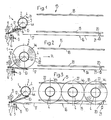
- Fig. 1 bis 3 in Seitenansicht eine Aufwickelstation in verschiedenen Arbeitsphasen,
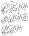
- Fig. 4 bis 6 ebenfalls in Seitenansicht eine Abwickelstation in verschiedenen Arbeitsphasen,
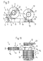
- Fig. 7 und 8 die Antriebs- und Lagerungseinheit der Aufwickelstation in Seitenansicht und teilweise im Schnitt,
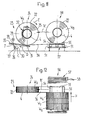
- Fig. 9 und 10 in Seitenansicht bzw. in Draufsicht eine Ausführungsform einer erfindungsgemässen Aufwickelstation, und
- Fig. 11 und 12 ebenfalls in Seitenansicht eine Ausführungsform einer erfindungsgemässen Abwickelstation.
- In den Fig. I bis 3 ist eine Aufwickelstation I in drei verschiedenen Arbeitsphasen gezeigt. Diese Aufwickelstation I weist eine eine Aufwickelstelle 2 festlegende Lagereinheit 3 auf, deren Aufbau in den Fig. 7 und 8 näher dargestellt ist. Diese Lagereinheit 3 dient zum Lagern von hohlzylindrischen Wickelkernen 4, so dass diese um ihre im wesentlichen horizontal verlaufende Achse 4a drehbar angetrieben werden können. Weiter ist eine Lagerung 5 für eine Vorratsspule 6 für ein Wickelband 7 vorhanden. Auf diese Vorratsspule 6 wirkt eine Bremsanordnung 8 ein. Das Wickelband 7 ist über eine Antriebsrolle 9 geführt und verläuft auf der Oberseite eines als Wippe ausgebildeten Bandförderers 10 zum Wickelkern 4, mit dem das Wickelband 7 verbunden ist. Der Bandförderer 10 ist um eine mit der Drehachse der Antriebsrolle 9 ausgerichtete Achse schwenkbar gelagert. Die Antriebsrolle 9 und auch der Bandförderer 10 werden von einem Antriebsmotor II angetrieben, der über ein Wicklergetriebe 12 den Wickelkern 4 in Richtung des Pfeiles B (Fig. I) antreibt. Dem Bandförderer 10 ist ein Zuförderer 13 vorgeschaltet, der die aufzuwickelnden Druckereierzeugnisse 14 in Schuppenformation S zuführt.
- Die Aufwickelstation I weist weiter ein benachbart zur Aufwickelstelle 2 angeordnetes Magazin 15 auf, das eine Auflage 16 für fertige Druckproduktewickel W aufweist. Diese Auflage 16 schliesst an eine Rollbahn 17 an, die sich bis zur Aufwickelstelle 2 hin erstreckt. Das Magazin 15 weist ferner seitliche Führungen 18 und 19 für die Wickel W auf. Diese Führungen 18, 19 können jedoch unter Umständen entfallen. In Rollrichtung R der Wickel W gesehen am hintern Ende des Magazin 15 ist eine Sperre 20 angeordnet, welche mittels eines Antriebes 21 gelöst werden kann. Mittels dieser Sperre wird ein Wegrollen der Wickel W verhindert.
- Die vom Zuförderer 13 zugeführte Schuppenformation S wird mit einer Flachseite der Druckereierzeugnisse 14 dem Wickelkern 4 zugekehrt zusammen mit dem unter Zugspannung stehenden Wickelband 7 auf den Wickelkern 4 aufgewickelt, der zu diesem Zweck durch den Motor II in Richtung des Pfeiles B angetrieben wird (Fig. I). Das Aufwickeln der Schuppenformation S auf den Wickelkern 4 erfolgt grundsätzlich auf die in der CH-PS 642 602 bzw. in der entsprechenden US-PS 4,438,618 beschriebene Weise.
- Nach Fertigstellung eines Wickels Wi (Fig. 2) wird dieser Wickel W1 aus der Aufwickelstelle 2 heraus in Richtung des Pfeiles R in das Magazin 15 herausgerollt. Dabei liegt der Wickel Wi mit den Druckereierzeugnissen 14 der äussersten Wicklungslage, d.h. mit seiner Umfangsfläche 22, auf der Rollbahn 17 und der Auflage 16 auf. Rollbahn 17 und Auflage 16 sind gegenüber der Horizontalen leicht geneigt, so dass der Wickel W1 sehr rasch und mit wenig Aufwand von der Wikkelstelle 2 weggerollt werden kann. Der Wickel W1 rollt bis zur Sperre 20, durch welche er an einem Weiterrollen gehindert wird.
- Sobald die Aufwickelstelle 2 frei ist, kann ein neuer Wikkelkern 4 eingesetzt und mit einem neuen Wickelband 7 verbunden werden. Damit ist die Aufwickelstation I zum Bilden eines neuen Wickels bereit.
- Jedesmal, wenn ein Wickel fertig ist, wird dieser auf die beschriebene Weise aus der Aufwickelstelle 2 heraus ins Magazin 15 gerollt. Dieses Magazin 15 ist in der Lage, eine Anzahl von Wickeln aufzunehmen. In der Fig. 3 sind drei sich im Magazin 15 befindliche Wickel W1, W2 und Ws gezeigt. Das Magazin 15 wirkt als Puffermagazin, dem die Wickel Wi, W2, Wa jederzeit entnommen und z.B. in ein Zwischenlager oder zu einer Abwickelstation gebracht werden können. Zu diesem Zwecke wird mittels des Antriebes 21 die Sperre 20 gelöst, was es einem Wickel, beispielsweise dem Wickel W1 ermöglicht, aus dem Magazin 15 herauszurollen. Der Weitertransport der dem Magazin 15 entnommenen Wickel W kann auf irgend eine geeignete Weise erfolgen. Währenddem am einen Ende des Magazins 15 letzterem Wickel zugeführt werden, können am andern Ende dem Magazin 15 Wickel entnommen werden. Die Wickel sind im Magazin 15 in Rollrichtung R gesehen hintereinander angeordnet und liegen mit ihrer Umfangsfläche 22 aneinander an.
- Da nach Fertigstellung eines Wickels W dieser nur in das benachbart zur Aufwickelstelle 2 angeordnete Magazin 15 gerollt werden muss, ist die Aufwickelstelle 2 sehr rasch zur Aufnahme eines leeren Wickelkernes bereit. Es sind keine zeit- und arbeitsaufwendige Handhabungen erforderlich, um einen vollen Wickel W aus der Aufwickelstelle 2 zu entfernen. Das Wegrollen der fertigen Wickel W bietet keine besonderen Probleme, da die Wickel nicht allzugross und nicht sehr schwer sind. Zudem sind die Wickel W sehr kompakt, so dass es zu keiner ins Gewicht fallenden Abplattung der Wickel kommt, welche ein leichtes Wegrollen der Wickel W erschweren würde.
- In den Fig. 4 bis 6 ist nun eine Abwickelstation 23 in verschiedenen Arbeitsphasen gezeigt. Diese Abwickelstation 23 ist der Aufwickelstation gemäss den Fig. bis 3 sehr ähnlich und weist eine eine Abwickelstelle 24 festlegende Lagereinheit 25 auf. Letztere dient zur drehbaren Lagerung der Wickel W um eine im wesentlichen horizontale Achse. Im weitern ist eine Lagerung 26 für Aufnahmespulen 27 für das Wickelband 7 vorhanden. Das Wickelband 7 wird über eine Antriebsrolle 28 geführt, welche von einem Motor 29 angetrieben wird, der über ein Wicklergetriebe 30 die Aufnahmespule 27 in Richtung des Pfeiles C dreht. Im weitem treibt der Motor 29 einen als Wippe ausgebildeten Bandförderer 31 an, dessen Förderrichtung in den Figuren mit D angegeben ist. Des weiteren ist eine auf den Wickelkern 4 wirkende Bremsanordnung 32 vorgesehen. Dem Bandförderer 31 ist ein Wegförderer 33 nachgeschaltet.
- Durch Antreiben der Antriebsrolle 28 wird das Wickelband 7 und mit diesem die aufgewickelten Druckereierzeugnisse 14- vom Wickel W abgewickelt und über den Bandförderer 31 und den Wegförderer 33 weggeführt. Das abgewickelte Wickelband 7 wird auf die Aufnahmespule 27 aufgewickelt. Der sich in Richtung des Pfeiles E (Fig. 4) drehende Wickel W wird mittels der Bremsanordnung 32 leicht gebremst. Das Abwickeln der Druckereierzeugnisse 14 von den Wickeln W erfolgt grundsätzlich auf die in der CH-PS 649 062 bzw. der entsprechenden US-PS 4,438,618 beschriebene Weise.
- Benachbart zur Abwickelstelle 24 ist ein Magazin 34 angeordnet, das ähnlich aufgebaut ist wie das Magazin 15 gemäss den Fig. I bis 3. So weist das Magazin 34 eine gegen die Abwickelstelle 24 leicht abfallende Auflage 35 für Wickel Ws, Ws, W7 auf, die in eine Rollbahn 36 übergeht, welche sich bis in die Abwickelstelle 24 hinein erstreckt. An seinem der Abwickelstelle 24 benachbarten Ende weist das Magazin 34 eine Sperre 37 auf, welche mittels eines Antriebes 38 betätigt werden kann. Diese Sperre 37 verhindert ein Herausrollen der Wickel W aus dem Magazin 34.
- Sobald alle Produkte eines Wickels, z.B. des Wickels W4 (Fig. 4) abgewickelt sind, wird der nun leere Wickelkern 4 aus der Aufwickelstelle 24 entfernt. Dasselbe trifft auch auf die Aufnahmespule 27 mit dem aufgewickelten Wickelband 7 zu. Durch Lösen der Sperre 37 wird nun der nächste Wickel Ws aus dem Magazin 34 zur Abwickelstelle 24 gerollt. Dabei liegt der Wickel Ws mit seiner Umfangsfläche 22 auf der Auflage 35 bzw. der Rollbahn 36 auf. Nach erfolgtem Verbinden des Wickelbandes 7 mit einer Aufnahmespule 27 kann mit dem Abwickeln der Druckereierzeugnisse 14 des Wikkels Ws begonnen werden. Die verbleibenden Wickel Ws und W7 rollen nach, werden jedoch durch die Sperre 37 am Herausrollen aus dem Magazin 34 gehindert.
- Durch Hereinrollen von neuen Wickeln in das Magazin 34 vom der Abwickelstelle 24 entgegengesetzten Ende des Magazines 34 her kann letzteres dauernd nachgefüllt werden.
- Gleich wie anhand der Aufwickelstation I gemäss den Fig. bis 3 beschrieben, ist es sehr schnell möglich, die Abwikkelstation 23 wieder zum Abwickeln eines neuen Wickels bebereit zu machen, nachdem alle Druckereierzeugnisse 14 von einem Wickel abgewickelt worden sind. Es sind keine langen Handhabungszeiten nötig, um jeweils einen neuen Wickel W in die Abwickelstelle 24 zu bringen.
- Anhand der Fig. 7 und 8 soll nun erläutert werden, wie die Lagereinheit 3 der Aufwickelstation I ausgebildet werden kann, um ein rasches Austauschen eines vollen Wickels W durch einen leeren Wickelkern 4 zu ermöglichen.
- Diese Lagereinheit 3 weist zwei in Richtung der Achse 3a aufeinander ausgerichtete, in einem Abstand voneinander endende Wellenstummel 39, 40 auf. Diese sind mittels Kugel- oder Wälzlagern 41,42 drehbar gelagert und tragen am einen Ende ein Ketten- oder Zahnrad 43, das vom Antriebsmotor II her über das Wicklergetriebe 12 angetrieben wird. Auf diesen Wellenstummeln 39, 40 sitzen Lagerhülsen 44, 45, die in Richtung der Pfeile F verschiebbar sind. Diese Verschiebbarkeit wird durch Keilverbindungen 46, 47 ermöglicht, über die die Lagerhülsen 44, 45 drehfest mit den Wellen 39, 40 verbunden sind. Die Verschiebung der Lagerhülsen 44, 45 erfolgt mittels den mit 48 und 49 bezeichneten Antrieben.
- In der Fig. 7 sind die Lagerhülsen 44, 45 in ihrer eingefahrenen Stellung gezeigt, in der sie in das Innere eines Wickelkernes 4 eingreifen und diesen lagern. Durch Zurückbewegen der Lagerhülsen 44, 45 in die in Fig. 8 gezeigte Lage kommen die Lagerhülsen 44, 45 ausser Eingriff mit dem Wickelkern 4, was es nun ermöglicht, den auf der Rollbahn 17 aufliegenden Wickel W wie anhand der Fig. 1 bis 3 beschrieben aus der Aufwickelstelle 2 herauszurollen. Dabei kann der Wickel W durch die Führungen 18 und 19 seitlich geführt und dadurch an einem Umkippen gehindert werden.
- Es versteht sich, dass die Lagereinheit der Abwickelstation 23 ähnlich wie in den Fig. 7 und 8 dargestellt ausgebildet werden kann.
- In den Fig. 9 und 10 ist nun eine erfindungsgemässe Weiterausgestaltung der Aufwickelstation 1 gezeigt. Diese Variante unterscheidet sich von der Ausführungsform gemäss den Fig. 1 bis 3 durch eine andere Ausgestaltung des benachbart zur Aufwickelstelle 2 angeordneten Magazines 50. Letzteres weist eine Palette 51 auf, die auf einer Rollenbahn 52 aufliegt. Mit 53 ist der Antrieb der Rollenbahn 52 bezeichnet. Diese Rollenbahn 52 weist eine Förderrichtung G auf, die etwa rechtwinklig zur Wegrollrichtung R der fertigen Wickel W verläuft. Die Aufwickelstelle 2 ist über die leicht geneigte Rollbahn 17 mit der Palette 51 verbunden.
- Die fertigen Wickel W werden wie anhand der Fig. 1 bis 3 erläutert aus der Aufwickelstelle 2 heraus in Richtung des Pfeiles R weggerollt und gelangen über die Rollbahn 17 zur Palette 51, auf der sie mit ihrer Umfangsfläche 22 zur Auflage kommen. Mittels Arretierelemente 54, 55 werden die Wickel W am Wegrollen von der Palette 51 gehindert.
- Nachdem ein fertiger Wickel W auf die Palette 51 gerollt worden ist, wird diese in Richtung des Pfeiles G vorgeschoben. Der nächste Wickel, z.B. der Wickel W4, kommt nun neben den vorher erstellten Wickel, z.B. den Wickel W3, zu liegen. Die gleich grossen Wickel Wh W2, W3, W4 sind nun mit ihren Flachseiten einander zugekehrt nebeneinander angeordnet, so dass die Wickelkernachsen 4a der sich auf der Palette 51 befindlichen Wickel miteinander fluchten.
- Für den Wegtransport der sich auf der Palette 51 befindlichen Wickel kann die Palette 51 mittels eines herkömmlichen Umschlaggerätes erfasst werden. Im Gegensatz zur Ausführungsform gemäss den Fig. 1 bis 3 werden somit die fertigen Wickel Wi, W2, W3, W4 nicht einzeln dem Magazin 50 entnommen, sondern als eine Anzahl von Wickeln enthaltende Transporteinheiten.
- Diese Transporteinheiten werden nach einer eventuellen Zwischenlagerung in ein Magazin 56 einer erfindungsgemässen Abwickelstation 23 eingefüllt, wie sie in den Fig. 11 und 12 gezeigt ist. Mit Ausnahme der Ausbildung des Magazines 56 entspricht diese Abwickelstation 23 der in den Fig. 4 bis 6 gezeigten Ausführungsform.
- Die Palette 51 mit den zu entleerenden Wickeln Ws, Ws, W7, W8 wird auf einen Teil des Magazines 56 gebildeten Rollenbahn 57 abgesetzt, welche mittels eines Antriebes 58 angetrieben werden kann. Die Förderrichtung dieser Rollenbahn 56 ist in Fig. 12 mit H bezeichnet.
- Die Wickel W werden von der Palette 51 über die Rollbahn 36 in Richtung des Pfeiles R' zur Abwickelstelle 24 gerollt, wie das anhand der Fig. 4 bis 6 näher erläutert wurde. Die Palette 51 wird jeweils in Richtung des Pfeiles H vorgeschoben, um die Wickel nacheinander in eine mit der Rollbahn 36 ausgerichtete Lage zu bringen.
Claims (4)
Priority Applications (1)
| Application Number | Priority Date | Filing Date | Title |
|---|---|---|---|
| AT87105247T ATE58705T1 (de) | 1986-04-28 | 1987-04-09 | Verfahren und vorrichtung zum verarbeiten von druckereierzeugnissen, wie zeitungen, zeitschriften und dergleichen. |
Applications Claiming Priority (2)
| Application Number | Priority Date | Filing Date | Title |
|---|---|---|---|
| CH173186 | 1986-04-28 | ||
| CH1731/86 | 1986-04-28 |
Publications (2)
| Publication Number | Publication Date |
|---|---|
| EP0243754A1 EP0243754A1 (de) | 1987-11-04 |
| EP0243754B1 true EP0243754B1 (de) | 1990-11-28 |
Family
ID=4217274
Family Applications (1)
| Application Number | Title | Priority Date | Filing Date |
|---|---|---|---|
| EP87105247A Expired - Lifetime EP0243754B1 (de) | 1986-04-28 | 1987-04-09 | Verfahren und Vorrichtung zum Verarbeiten von Druckereierzeugnissen, wie Zeitungen, Zeitschriften und dergleichen |
Country Status (6)
| Country | Link |
|---|---|
| US (1) | US5012988A (de) |
| EP (1) | EP0243754B1 (de) |
| JP (1) | JP2759647B2 (de) |
| AT (1) | ATE58705T1 (de) |
| CA (1) | CA1297464C (de) |
| DE (1) | DE3766407D1 (de) |
Families Citing this family (1)
| Publication number | Priority date | Publication date | Assignee | Title |
|---|---|---|---|---|
| US20050161876A1 (en) * | 2002-01-09 | 2005-07-28 | Rafe Patterson | Method for storing, transporting and dispensing cartons |
Citations (2)
| Publication number | Priority date | Publication date | Assignee | Title |
|---|---|---|---|---|
| DE941600C (de) * | 1941-03-11 | 1956-04-12 | Siemag Siegener Maschb Ges Mit | Vorrichtung zum Stapeln und Weiterleiten von gewickelten Baendern und Drahtwickeln |
| WO1985001279A1 (fr) * | 1983-09-19 | 1985-03-28 | Ferag Ag | Enroulement de produits comprimes |
Family Cites Families (19)
| Publication number | Priority date | Publication date | Assignee | Title |
|---|---|---|---|---|
| US2508566A (en) * | 1946-06-10 | 1950-05-23 | Diamond Match Co | Web roll backstand |
| GB1082033A (en) * | 1965-04-12 | 1967-09-06 | Kleinewefers Soehne J | Winding-off apparatus for material lengths wound on reels, especially paper reels |
| US3586253A (en) * | 1969-02-06 | 1971-06-22 | Beloit Corp | Reel loader for paper machines or the like |
| BE787612A (fr) * | 1971-08-16 | 1973-02-16 | Monsanto Co | Procede continu de polymerisation en masse |
| FR2206160B1 (de) * | 1972-11-11 | 1977-09-09 | Fleck Soehne Gmbh C | |
| CH559691A5 (en) * | 1973-06-25 | 1975-03-14 | Burda Farben Kg | Non-cohesive sheet storage mechanism - accommodates staggered sheets between two belts winding onto drum |
| US3977617A (en) * | 1973-07-12 | 1976-08-31 | Salmon Marion B | Film winding and perforating apparatus |
| JPS533226Y2 (de) * | 1974-01-28 | 1978-01-27 | ||
| JPS53115308A (en) * | 1977-03-04 | 1978-10-07 | Tokyo Kikai Seisakushiyo Kk | Device for automatically supplying rolled paper in rotary press |
| US4265411A (en) * | 1979-07-18 | 1981-05-05 | Fasolak Ambrozy J | Paper roll backstand |
| DD158476A3 (de) * | 1980-06-23 | 1983-01-19 | Klaus Gebhardt | Vorrichtung zum einspannen von wickelhuelsen |
| CH642602A5 (de) * | 1980-07-15 | 1984-04-30 | Ferag Ag | Einrichtung zum stapeln von im schuppenstrom anfallenden druckprodukten, wie zeitungen, zeitschriften und dergleichen. |
| EP0054735B1 (de) * | 1980-12-23 | 1985-01-16 | Windmöller & Hölscher | Vorrichtung zum Herstellen von Schuppenbandrollen aus geschuppt Übereinander abgelegten flachen flexiblen Gegenständen |
| CH652701A5 (de) * | 1981-02-03 | 1985-11-29 | Ferag Ag | Verfahren und einrichtung zur erzielung eines langzeitpressungseffekts bei druckprodukten, insbesondere zeitungen. |
| IT1145030B (it) * | 1981-02-25 | 1986-11-05 | Gd Spa | Dispositivo per l'alimentazione automatica di bobine ad una macchina operatrice |
| JPS5859144A (ja) * | 1981-09-30 | 1983-04-08 | Rengo Co Ltd | ミルロ−ルスタンド |
| CH656596A5 (de) * | 1982-05-05 | 1986-07-15 | Grapha Holding Ag | Verfahren zum vereinzeln der druckbogen eines in teilschuppen unterteilten schuppenstroms. |
| CH657832A5 (de) * | 1982-06-09 | 1986-09-30 | Grapha Holding Ag | Beschickungs- und/oder lagereinrichtung fuer bogen, insbesondere druckbogen. |
| SU1584747A3 (ru) * | 1986-04-28 | 1990-08-07 | Фераг Аг (Фирма) | Устройство дл штабелировани рулонов и разбора штабел из них |
-
1987
- 1987-03-19 JP JP62065506A patent/JP2759647B2/ja not_active Expired - Lifetime
- 1987-04-09 EP EP87105247A patent/EP0243754B1/de not_active Expired - Lifetime
- 1987-04-09 DE DE8787105247T patent/DE3766407D1/de not_active Expired - Fee Related
- 1987-04-09 AT AT87105247T patent/ATE58705T1/de not_active IP Right Cessation
- 1987-04-27 CA CA000535656A patent/CA1297464C/en not_active Expired - Fee Related
-
1989
- 1989-07-28 US US07/388,305 patent/US5012988A/en not_active Expired - Fee Related
Patent Citations (2)
| Publication number | Priority date | Publication date | Assignee | Title |
|---|---|---|---|---|
| DE941600C (de) * | 1941-03-11 | 1956-04-12 | Siemag Siegener Maschb Ges Mit | Vorrichtung zum Stapeln und Weiterleiten von gewickelten Baendern und Drahtwickeln |
| WO1985001279A1 (fr) * | 1983-09-19 | 1985-03-28 | Ferag Ag | Enroulement de produits comprimes |
Also Published As
| Publication number | Publication date |
|---|---|
| EP0243754A1 (de) | 1987-11-04 |
| ATE58705T1 (de) | 1990-12-15 |
| JPS62255348A (ja) | 1987-11-07 |
| JP2759647B2 (ja) | 1998-05-28 |
| CA1297464C (en) | 1992-03-17 |
| US5012988A (en) | 1991-05-07 |
| DE3766407D1 (de) | 1991-01-10 |
Similar Documents
| Publication | Publication Date | Title |
|---|---|---|
| DE3702379C2 (de) | ||
| DE3824843C2 (de) | ||
| AT393493B (de) | Foerdervorrichtung zum zufuehren von leeren wickelhuelsen fuer aufwickelmaschinen fuer laengsgeteilte bahnen | |
| DE3015547C2 (de) | Wickelmaschine für bahnförmiges Gut | |
| EP0925246B2 (de) | Verfahren zum transport von rollen zu einem rollenwechsler | |
| DE3308171A1 (de) | Kopstransportsystem fuer einen spulautomaten | |
| EP0261508B1 (de) | Einrichtung zum Transport von Bobinen aus Verpackungsmaterial in einer Verpackungsmaschinenanlage | |
| DE3026995A1 (de) | Verfahren und vorrichtung zum aneinanderschliessen von verpackungsmaterial-bahnen in verpackungsmaschinen | |
| CH652699A5 (de) | Einrichtung zum speichern von in einer schuppenformation anfallenden flaechigen erzeugnissen, insbesondere druckprodukten. | |
| EP0243837B1 (de) | Vorrichtung zum Verarbeiten von Druckereierzeugnissen wie Zeitungen, Zeitschriften und dergleichen | |
| WO1998012132A1 (de) | Transportwagen für papierrollen | |
| DE2600522C2 (de) | ||
| EP0229888B1 (de) | Vorrichtung zum Speichern von in Schuppenformation anfallenden Druckprodukten | |
| DE2033385A1 (de) | Vorrichtung zur Vorbereitung von Rollen aus blattförmigem Material zum Abwickeln | |
| DE4234344C2 (de) | Vorrichtung für eine Produktionsmaschine zum Wechseln von Rollen bahnförmigen Materials | |
| EP0236561B1 (de) | Verfahren zum Zwischenspeichern von in Schuppenformation anfallenden Druckereierzeugnissen, wie Zeitungen, Zeitschriften und dergleichen | |
| DE60217244T2 (de) | Vorrichtung zum Positionieren einer Hülse | |
| EP0243753B1 (de) | Verfahren und Vorrichtung zum Verarbeiten von in Schuppenformation anfallenden Druckereierzeugnissen, wie Zeitungen, Zeitschriften und dergleichen | |
| DE3318496A1 (de) | Vorrichtung zum liefern von papphuelsen an eine fadenwickelmaschine | |
| DE2308351C3 (de) | Automatisch arbeitende Maschine zum Aufwickeln von Drahtlitzen | |
| EP0243838B1 (de) | Verfahren und Vorrichtung zum Verarbeiten von flächigen Erzeugnissen, insbesondere Druckereierzeugnissen | |
| EP0243754B1 (de) | Verfahren und Vorrichtung zum Verarbeiten von Druckereierzeugnissen, wie Zeitungen, Zeitschriften und dergleichen | |
| DE3815831A1 (de) | Spulentransportsystem | |
| EP0230677B1 (de) | Verfahren und Vorrichtung zum Verarbeiten von in Schuppenformation anfallenden Druckereierzeugnissen wie Zeitungen, Zeitschriften und dergleichen | |
| EP0887297B1 (de) | Wickeleinrichtung für eine Materialbahn, insbesondere für eine Rollenschneidvorrichtung |
Legal Events
| Date | Code | Title | Description |
|---|---|---|---|
| PUAI | Public reference made under article 153(3) epc to a published international application that has entered the european phase |
Free format text: ORIGINAL CODE: 0009012 |
|
| AK | Designated contracting states |
Kind code of ref document: A1 Designated state(s): AT CH DE FR GB IT LI SE |
|
| 17P | Request for examination filed |
Effective date: 19871007 |
|
| 17Q | First examination report despatched |
Effective date: 19880722 |
|
| GRAA | (expected) grant |
Free format text: ORIGINAL CODE: 0009210 |
|
| AK | Designated contracting states |
Kind code of ref document: B1 Designated state(s): AT CH DE FR GB IT LI SE |
|
| REF | Corresponds to: |
Ref document number: 58705 Country of ref document: AT Date of ref document: 19901215 Kind code of ref document: T |
|
| GBT | Gb: translation of ep patent filed (gb section 77(6)(a)/1977) | ||
| ET | Fr: translation filed | ||
| REF | Corresponds to: |
Ref document number: 3766407 Country of ref document: DE Date of ref document: 19910110 |
|
| ITF | It: translation for a ep patent filed | ||
| PLBE | No opposition filed within time limit |
Free format text: ORIGINAL CODE: 0009261 |
|
| STAA | Information on the status of an ep patent application or granted ep patent |
Free format text: STATUS: NO OPPOSITION FILED WITHIN TIME LIMIT |
|
| 26N | No opposition filed | ||
| ITTA | It: last paid annual fee | ||
| EAL | Se: european patent in force in sweden |
Ref document number: 87105247.8 |
|
| PGFP | Annual fee paid to national office [announced via postgrant information from national office to epo] |
Ref country code: FR Payment date: 19950320 Year of fee payment: 9 |
|
| PGFP | Annual fee paid to national office [announced via postgrant information from national office to epo] |
Ref country code: AT Payment date: 19950321 Year of fee payment: 9 |
|
| PGFP | Annual fee paid to national office [announced via postgrant information from national office to epo] |
Ref country code: SE Payment date: 19950322 Year of fee payment: 9 |
|
| PG25 | Lapsed in a contracting state [announced via postgrant information from national office to epo] |
Ref country code: AT Effective date: 19960409 |
|
| PG25 | Lapsed in a contracting state [announced via postgrant information from national office to epo] |
Ref country code: SE Effective date: 19960410 |
|
| PG25 | Lapsed in a contracting state [announced via postgrant information from national office to epo] |
Ref country code: FR Effective date: 19961227 |
|
| EUG | Se: european patent has lapsed |
Ref document number: 87105247.8 |
|
| REG | Reference to a national code |
Ref country code: FR Ref legal event code: ST |
|
| PGFP | Annual fee paid to national office [announced via postgrant information from national office to epo] |
Ref country code: GB Payment date: 20010316 Year of fee payment: 15 |
|
| PGFP | Annual fee paid to national office [announced via postgrant information from national office to epo] |
Ref country code: DE Payment date: 20010421 Year of fee payment: 15 |
|
| PGFP | Annual fee paid to national office [announced via postgrant information from national office to epo] |
Ref country code: CH Payment date: 20010427 Year of fee payment: 15 |
|
| REG | Reference to a national code |
Ref country code: GB Ref legal event code: IF02 |
|
| PG25 | Lapsed in a contracting state [announced via postgrant information from national office to epo] |
Ref country code: GB Free format text: LAPSE BECAUSE OF NON-PAYMENT OF DUE FEES Effective date: 20020409 |
|
| PG25 | Lapsed in a contracting state [announced via postgrant information from national office to epo] |
Ref country code: LI Free format text: LAPSE BECAUSE OF NON-PAYMENT OF DUE FEES Effective date: 20020430 Ref country code: CH Free format text: LAPSE BECAUSE OF NON-PAYMENT OF DUE FEES Effective date: 20020430 |
|
| PG25 | Lapsed in a contracting state [announced via postgrant information from national office to epo] |
Ref country code: DE Free format text: LAPSE BECAUSE OF NON-PAYMENT OF DUE FEES Effective date: 20021101 |
|
| GBPC | Gb: european patent ceased through non-payment of renewal fee |
Effective date: 20020409 |
|
| REG | Reference to a national code |
Ref country code: CH Ref legal event code: PL |
|
| PG25 | Lapsed in a contracting state [announced via postgrant information from national office to epo] |
Ref country code: IT Free format text: LAPSE BECAUSE OF NON-PAYMENT OF DUE FEES;WARNING: LAPSES OF ITALIAN PATENTS WITH EFFECTIVE DATE BEFORE 2007 MAY HAVE OCCURRED AT ANY TIME BEFORE 2007. THE CORRECT EFFECTIVE DATE MAY BE DIFFERENT FROM THE ONE RECORDED. Effective date: 20050409 |