EP0243754B1 - Procédé et dispositif pour traiter des produits imprimés comme des journaux, des magazines et analogues - Google Patents
Procédé et dispositif pour traiter des produits imprimés comme des journaux, des magazines et analogues Download PDFInfo
- Publication number
- EP0243754B1 EP0243754B1 EP87105247A EP87105247A EP0243754B1 EP 0243754 B1 EP0243754 B1 EP 0243754B1 EP 87105247 A EP87105247 A EP 87105247A EP 87105247 A EP87105247 A EP 87105247A EP 0243754 B1 EP0243754 B1 EP 0243754B1
- Authority
- EP
- European Patent Office
- Prior art keywords
- winding
- location
- rolls
- magazine
- unwinding
- Prior art date
- Legal status (The legal status is an assumption and is not a legal conclusion. Google has not performed a legal analysis and makes no representation as to the accuracy of the status listed.)
- Expired - Lifetime
Links
- 238000000034 method Methods 0.000 title claims description 4
- 238000004804 winding Methods 0.000 claims abstract description 129
- 238000005096 rolling process Methods 0.000 claims abstract description 17
- 230000015572 biosynthetic process Effects 0.000 claims abstract description 8
- 238000012545 processing Methods 0.000 claims description 4
- 230000000903 blocking effect Effects 0.000 claims 2
- 238000009472 formulation Methods 0.000 claims 2
- 239000000203 mixture Substances 0.000 claims 2
- 230000000284 resting effect Effects 0.000 claims 2
- 230000002093 peripheral effect Effects 0.000 description 4
- 238000012432 intermediate storage Methods 0.000 description 3
- 238000003860 storage Methods 0.000 description 2
- 238000010276 construction Methods 0.000 description 1
- 238000013461 design Methods 0.000 description 1
- 238000011161 development Methods 0.000 description 1
- 238000003780 insertion Methods 0.000 description 1
- 230000037431 insertion Effects 0.000 description 1
Images

Classifications
-
- B—PERFORMING OPERATIONS; TRANSPORTING
- B65—CONVEYING; PACKING; STORING; HANDLING THIN OR FILAMENTARY MATERIAL
- B65H—HANDLING THIN OR FILAMENTARY MATERIAL, e.g. SHEETS, WEBS, CABLES
- B65H29/00—Delivering or advancing articles from machines; Advancing articles to or into piles
- B65H29/66—Advancing articles in overlapping streams
-
- B—PERFORMING OPERATIONS; TRANSPORTING
- B65—CONVEYING; PACKING; STORING; HANDLING THIN OR FILAMENTARY MATERIAL
- B65H—HANDLING THIN OR FILAMENTARY MATERIAL, e.g. SHEETS, WEBS, CABLES
- B65H29/00—Delivering or advancing articles from machines; Advancing articles to or into piles
- B65H29/006—Winding articles into rolls
-
- B—PERFORMING OPERATIONS; TRANSPORTING
- B65—CONVEYING; PACKING; STORING; HANDLING THIN OR FILAMENTARY MATERIAL
- B65H—HANDLING THIN OR FILAMENTARY MATERIAL, e.g. SHEETS, WEBS, CABLES
- B65H5/00—Feeding articles separated from piles; Feeding articles to machines
- B65H5/24—Feeding articles in overlapping streams, i.e. by separation of articles from a pile
-
- B—PERFORMING OPERATIONS; TRANSPORTING
- B65—CONVEYING; PACKING; STORING; HANDLING THIN OR FILAMENTARY MATERIAL
- B65H—HANDLING THIN OR FILAMENTARY MATERIAL, e.g. SHEETS, WEBS, CABLES
- B65H5/00—Feeding articles separated from piles; Feeding articles to machines
- B65H5/28—Feeding articles stored in rolled or folded bands
-
- B—PERFORMING OPERATIONS; TRANSPORTING
- B65—CONVEYING; PACKING; STORING; HANDLING THIN OR FILAMENTARY MATERIAL
- B65H—HANDLING THIN OR FILAMENTARY MATERIAL, e.g. SHEETS, WEBS, CABLES
- B65H2301/00—Handling processes for sheets or webs
- B65H2301/40—Type of handling process
- B65H2301/41—Winding, unwinding
- B65H2301/419—Winding, unwinding from or to storage, i.e. the storage integrating winding or unwinding means
- B65H2301/4192—Winding, unwinding from or to storage, i.e. the storage integrating winding or unwinding means for handling articles of limited length in shingled formation
- B65H2301/41922—Winding, unwinding from or to storage, i.e. the storage integrating winding or unwinding means for handling articles of limited length in shingled formation and wound together with single belt like members
-
- B—PERFORMING OPERATIONS; TRANSPORTING
- B65—CONVEYING; PACKING; STORING; HANDLING THIN OR FILAMENTARY MATERIAL
- B65H—HANDLING THIN OR FILAMENTARY MATERIAL, e.g. SHEETS, WEBS, CABLES
- B65H2701/00—Handled material; Storage means
- B65H2701/10—Handled articles or webs
- B65H2701/19—Specific article or web
- B65H2701/1932—Signatures, folded printed matter, newspapers or parts thereof and books
-
- B—PERFORMING OPERATIONS; TRANSPORTING
- B65—CONVEYING; PACKING; STORING; HANDLING THIN OR FILAMENTARY MATERIAL
- B65H—HANDLING THIN OR FILAMENTARY MATERIAL, e.g. SHEETS, WEBS, CABLES
- B65H2801/00—Application field
- B65H2801/03—Image reproduction devices
- B65H2801/21—Industrial-size printers, e.g. rotary printing press
Definitions
- the present invention relates to methods and devices for processing printed products, such as newspapers, magazines and the like, in scale formation according to the preamble of claims 1 and 2.
- the present invention has for its object to provide a method and an apparatus of the type mentioned that a quick and easy unloading of the winding station or a quick and easy loading of an unwinding station and a rational handling of the reel with the least possible time and equipment Enable effort.
- the winding point By rolling the finished roll out of the winding point into an adjacent buffer magazine and onto a support designed as a transport element, the winding point is very quickly free to insert an empty winding core after completion of a winding, so that the winding point is ready again for forming the next roll after a short time is.
- This rapid changeover also makes it possible to produce coils with smaller diameters, which are completed in a shorter time than large coils.
- the transport of the wraps lying on the support can be done in a time-saving manner and with conventional handling means.
- a roll can be rolled very quickly from the buffer magazine arranged adjacent to the unwinding point to the unwinding point and made ready for unwinding.
- the supports, each loaded with a number of reels, can also be brought to the unwinding station using conventional handling equipment.
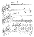
- This winding station I has a bearing unit 3 which defines a winding point 2, the structure of which is shown in more detail in FIGS. 7 and 8.
- This bearing unit 3 serves for the storage of hollow cylindrical winding cores 4, so that they can be driven rotatably about their essentially horizontal axis 4a.
- a brake arrangement 8 acts on this supply spool 6.
- the winding tape 7 is guided over a drive roller 9 and runs on the top of a belt conveyor 10 designed as a rocker to the winding core 4, to which the winding tape 7 is connected.
- the belt conveyor 10 is pivotally mounted about an axis aligned with the axis of rotation of the drive roller 9.
- the drive roller 9 and also the belt conveyor 10 are driven by a drive motor II which drives the winding core 4 in the direction of arrow B (FIG. I) via a winder gear 12.
- the belt conveyor 10 is preceded by a feed conveyor 13 which is to be wound up Feeds printed products 14 in scale formation S.
- the winding station I also has a magazine 15 which is arranged adjacent to the winding point 2 and has a support 16 for finished printed product rolls W.
- This support 16 connects to a runway 17 which extends to the take-up point 2.
- the magazine 15 also has lateral guides 18 and 19 for the winding W. These guides 18, 19 can, however, possibly be omitted.
- a lock 20 Viewed in the rolling direction R of the winding W at the rear end of the magazine 15 there is a lock 20 which can be released by means of a drive 21. This lock prevents the winding W from rolling away.
- the scale formation S fed by the feed conveyor 13 is turned with a flat side of the printed products 14 facing the winding core 4 together with the winding tape 7 under tension on the winding core 4, which is driven for this purpose by the motor II in the direction of arrow B (FIG. I).
- the winding formation S on the winding core 4 is basically carried out in the manner described in CH-PS 642 602 or in the corresponding US-PS 4,438,618.
- this roll W 1 After completion of a roll W i (FIG. 2), this roll W 1 is rolled out of the take-up point 2 in the direction of arrow R into the magazine 15.
- the runway 17 and support 16 are slightly inclined with respect to the horizontal, so that the winding W 1 can be rolled away from the winding point 2 very quickly and with little effort.
- the winding W 1 rolls up to the lock 20, by which it is prevented from continuing to roll.
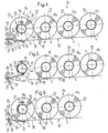
- This magazine 15 is able to accommodate a number of coils.
- 3 shows three windings W 1 , W 2 and Ws located in the magazine 15.
- the magazine 15 acts as a buffer magazine from which the windings Wi, W 2 , Wa can be removed at any time and can be brought, for example, to an intermediate store or to an unwinding station.
- the lock 20 is released by means of the drive 21, which enables a winding, for example the winding W 1 , to roll out of the magazine 15.
- the winding W removed from the magazine 15 can be transported further in any suitable manner.
- windings can be removed from the magazine at the other end.
- the windings are arranged one behind the other in the magazine 15 as viewed in the rolling direction R and rest against one another with their peripheral surface 22.
- an unwinding station 23 is now shown in different working phases.
- This unwinding station 23 is very similar to the unwinding station according to FIGS. 1 to 3 and has a bearing unit 25 which defines an unwinding point 24.
- the latter serves for the rotatable mounting of the winding W about an essentially horizontal axis.
- the winding tape 7 is guided over a drive roller 28 which is driven by a motor 29 which rotates the take-up spool 27 in the direction of arrow C via a winder gear 30.
- the motor 29 largely drives a belt conveyor 31 designed as a rocker, the direction of conveyance of which is indicated by D in the figures.
- a brake arrangement 32 acting on the winding core 4 is provided.
- a belt conveyor 33 is connected downstream of the belt conveyor 31.
- the winding tape 7 and with it the wound printed products 14 are unwound from the winding W and guided away via the belt conveyor 31 and the removal conveyor 33.
- the unwound winding tape 7 is wound on the take-up spool 27.
- the winding W rotating in the direction of arrow E (FIG. 4) is slightly braked by means of the brake arrangement 32.
- the unwinding of the printed products 14 from the coils W is basically carried out in the manner described in CH-PS 649 062 or the corresponding US-PS 4,438,618.
- a magazine 34 Adjacent to unwind location 24, a magazine 34 is arranged, which is similar in construction to the magazine 15 according to FIGS. I to 3.
- the magazine 34 has a slightly sloping against the unwind 24 table 35 for winding Ws, Ws, W 7, which merges into a runway 36 which extends into the unwinding point 24.
- the magazine 34 At its end adjacent to the unwinding point 24, the magazine 34 has a lock 37 which can be actuated by means of a drive 38. This lock 37 prevents the winding W from rolling out of the magazine 34.
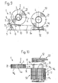
- This bearing unit 3 has two shaft ends 39, 40 aligned with one another in the direction of the axis 3a and ending at a distance from one another. These are rotatably mounted by means of ball or roller bearings 41, 42 and carry at one end a chain or gear 43 which is driven by the drive motor II via the winder gear 12. Bearing sleeves 44, 45, which can be displaced in the direction of the arrows F, sit on these shaft ends 39, 40. This displaceability is made possible by wedge connections 46, 47 via which the bearing sleeves 44, 45 are connected to the shafts 39, 40 in a rotationally fixed manner. The bearing sleeves 44, 45 are displaced by means of the drives designated 48 and 49.
- Fig. 7 the bearing sleeves 44, 45 are shown in their retracted position in which they engage in the inside of a winding core 4 and store it.
- the bearing sleeves 44, 45 come out of engagement with the winding core 4, which now enables the winding W lying on the runway 17 as described with reference to FIGS. 1 to 3 roll out of the take-up point 2.
- the winding W can be guided laterally through the guides 18 and 19 and thereby prevented from tipping over.
- bearing unit of the unwinding station 23 can be designed similarly to that shown in FIGS. 7 and 8.
- FIGS. 1 to 3 differs from the embodiment according to FIGS. 1 to 3 by a different configuration of the magazine 50 arranged adjacent to the winding point 2.
- the latter has a pallet 51 which rests on a roller conveyor 52. With 53 the drive of the roller conveyor 52 is designated.
- This roller conveyor 52 has a conveying direction G which is approximately at right angles to the rolling direction R of the finished roll W.
- the winding point 2 is connected to the pallet 51 via the slightly inclined runway 17.
- the finished rolls W are rolled out of the take-up point 2 in the direction of arrow R, as explained with reference to FIGS. 1 to 3, and reach the pallet 51 via the runway 17, on which they rest with their peripheral surface 22.
- the windings W are prevented from rolling away from the pallet 51 by means of locking elements 54, 55.
- a finished roll W After a finished roll W has been rolled onto the pallet 51, it is advanced in the direction of the arrow G.
- the next winding for example the winding W 4 , now comes to lie next to the previously created winding, for example the winding W 3 .
- the coils of the same size Wh W 2 , W 3 , W 4 are now arranged with their flat sides facing one another, so that the winding core axes 4a of the coils located on the pallet 51 are aligned with one another.
- the pallet 51 can be gripped by means of a conventional handling device for the transport away of the windings located on the pallet 51.
- the finished reels Wi, W 2 , W 3 , W 4 are therefore not removed individually from the magazine 50, but rather as transport units containing a number of reels.
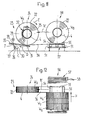
- these transport units are filled into a magazine 56 of an unwinding station 23 according to the invention, as is shown in FIGS. 11 and 12.
- this unwinding station 23 corresponds to the embodiment shown in FIGS. 4 to 6.
- the pallet 51 with the windings Ws, Ws, W 7 , W 8 to be emptied is placed on a part of the roller conveyor 57 formed in the magazine 56, which can be driven by a drive 58.
- the conveying direction of this roller conveyor 56 is designated by H in FIG.
- the windings W are rolled from the pallet 51 over the roller conveyor 36 in the direction of the arrow R 'to the unwinding point 24, as was explained in more detail with reference to FIGS. 4 to 6.
- the pallet 51 is advanced in the direction of arrow H in order to bring the windings one after the other into a position aligned with the runway 36.
Landscapes
- Engineering & Computer Science (AREA)
- Mechanical Engineering (AREA)
- Replacement Of Web Rolls (AREA)
- Discharge By Other Means (AREA)
- Unwinding Webs (AREA)
- Winding Of Webs (AREA)
- Packaging Of Special Articles (AREA)
- Basic Packing Technique (AREA)
Claims (4)
Priority Applications (1)
| Application Number | Priority Date | Filing Date | Title |
|---|---|---|---|
| AT87105247T ATE58705T1 (de) | 1986-04-28 | 1987-04-09 | Verfahren und vorrichtung zum verarbeiten von druckereierzeugnissen, wie zeitungen, zeitschriften und dergleichen. |
Applications Claiming Priority (2)
| Application Number | Priority Date | Filing Date | Title |
|---|---|---|---|
| CH1731/86 | 1986-04-28 | ||
| CH173186 | 1986-04-28 |
Publications (2)
| Publication Number | Publication Date |
|---|---|
| EP0243754A1 EP0243754A1 (fr) | 1987-11-04 |
| EP0243754B1 true EP0243754B1 (fr) | 1990-11-28 |
Family
ID=4217274
Family Applications (1)
| Application Number | Title | Priority Date | Filing Date |
|---|---|---|---|
| EP87105247A Expired - Lifetime EP0243754B1 (fr) | 1986-04-28 | 1987-04-09 | Procédé et dispositif pour traiter des produits imprimés comme des journaux, des magazines et analogues |
Country Status (6)
| Country | Link |
|---|---|
| US (1) | US5012988A (fr) |
| EP (1) | EP0243754B1 (fr) |
| JP (1) | JP2759647B2 (fr) |
| AT (1) | ATE58705T1 (fr) |
| CA (1) | CA1297464C (fr) |
| DE (1) | DE3766407D1 (fr) |
Families Citing this family (1)
| Publication number | Priority date | Publication date | Assignee | Title |
|---|---|---|---|---|
| EP1463676A2 (fr) * | 2002-01-09 | 2004-10-06 | Meadwestvaco Packaging Systems, LLP | Procede de stockage, de transport et de distribution de caisses en carton |
Citations (2)
| Publication number | Priority date | Publication date | Assignee | Title |
|---|---|---|---|---|
| DE941600C (de) * | 1941-03-11 | 1956-04-12 | Siemag Siegener Maschb Ges Mit | Vorrichtung zum Stapeln und Weiterleiten von gewickelten Baendern und Drahtwickeln |
| WO1985001279A1 (fr) * | 1983-09-19 | 1985-03-28 | Ferag Ag | Enroulement de produits comprimes |
Family Cites Families (19)
| Publication number | Priority date | Publication date | Assignee | Title |
|---|---|---|---|---|
| US2508566A (en) * | 1946-06-10 | 1950-05-23 | Diamond Match Co | Web roll backstand |
| GB1082033A (en) * | 1965-04-12 | 1967-09-06 | Kleinewefers Soehne J | Winding-off apparatus for material lengths wound on reels, especially paper reels |
| US3586253A (en) * | 1969-02-06 | 1971-06-22 | Beloit Corp | Reel loader for paper machines or the like |
| BE787612A (fr) * | 1971-08-16 | 1973-02-16 | Monsanto Co | Procede continu de polymerisation en masse |
| FR2206160B1 (fr) * | 1972-11-11 | 1977-09-09 | Fleck Soehne Gmbh C | |
| CH559691A5 (en) * | 1973-06-25 | 1975-03-14 | Burda Farben Kg | Non-cohesive sheet storage mechanism - accommodates staggered sheets between two belts winding onto drum |
| US3977617A (en) * | 1973-07-12 | 1976-08-31 | Salmon Marion B | Film winding and perforating apparatus |
| JPS533226Y2 (fr) * | 1974-01-28 | 1978-01-27 | ||
| JPS53115308A (en) * | 1977-03-04 | 1978-10-07 | Tokyo Kikai Seisakushiyo Kk | Device for automatically supplying rolled paper in rotary press |
| US4265411A (en) * | 1979-07-18 | 1981-05-05 | Fasolak Ambrozy J | Paper roll backstand |
| DD158476A3 (de) * | 1980-06-23 | 1983-01-19 | Klaus Gebhardt | Vorrichtung zum einspannen von wickelhuelsen |
| CH642602A5 (de) * | 1980-07-15 | 1984-04-30 | Ferag Ag | Einrichtung zum stapeln von im schuppenstrom anfallenden druckprodukten, wie zeitungen, zeitschriften und dergleichen. |
| EP0054735B1 (fr) * | 1980-12-23 | 1985-01-16 | Windmöller & Hölscher | Dispositif de fabrication de rouleaux de bandes formées à partir de feuilles souples imbriqueés |
| CH652701A5 (de) * | 1981-02-03 | 1985-11-29 | Ferag Ag | Verfahren und einrichtung zur erzielung eines langzeitpressungseffekts bei druckprodukten, insbesondere zeitungen. |
| IT1145030B (it) * | 1981-02-25 | 1986-11-05 | Gd Spa | Dispositivo per l'alimentazione automatica di bobine ad una macchina operatrice |
| JPS5859144A (ja) * | 1981-09-30 | 1983-04-08 | Rengo Co Ltd | ミルロ−ルスタンド |
| CH656596A5 (de) * | 1982-05-05 | 1986-07-15 | Grapha Holding Ag | Verfahren zum vereinzeln der druckbogen eines in teilschuppen unterteilten schuppenstroms. |
| CH657832A5 (de) * | 1982-06-09 | 1986-09-30 | Grapha Holding Ag | Beschickungs- und/oder lagereinrichtung fuer bogen, insbesondere druckbogen. |
| SU1584747A3 (ru) * | 1986-04-28 | 1990-08-07 | Фераг Аг (Фирма) | Устройство дл штабелировани рулонов и разбора штабел из них |
-
1987
- 1987-03-19 JP JP62065506A patent/JP2759647B2/ja not_active Expired - Lifetime
- 1987-04-09 DE DE8787105247T patent/DE3766407D1/de not_active Expired - Fee Related
- 1987-04-09 AT AT87105247T patent/ATE58705T1/de not_active IP Right Cessation
- 1987-04-09 EP EP87105247A patent/EP0243754B1/fr not_active Expired - Lifetime
- 1987-04-27 CA CA000535656A patent/CA1297464C/fr not_active Expired - Fee Related
-
1989
- 1989-07-28 US US07/388,305 patent/US5012988A/en not_active Expired - Fee Related
Patent Citations (2)
| Publication number | Priority date | Publication date | Assignee | Title |
|---|---|---|---|---|
| DE941600C (de) * | 1941-03-11 | 1956-04-12 | Siemag Siegener Maschb Ges Mit | Vorrichtung zum Stapeln und Weiterleiten von gewickelten Baendern und Drahtwickeln |
| WO1985001279A1 (fr) * | 1983-09-19 | 1985-03-28 | Ferag Ag | Enroulement de produits comprimes |
Also Published As
| Publication number | Publication date |
|---|---|
| JP2759647B2 (ja) | 1998-05-28 |
| EP0243754A1 (fr) | 1987-11-04 |
| CA1297464C (fr) | 1992-03-17 |
| DE3766407D1 (de) | 1991-01-10 |
| US5012988A (en) | 1991-05-07 |
| ATE58705T1 (de) | 1990-12-15 |
| JPS62255348A (ja) | 1987-11-07 |
Similar Documents
| Publication | Publication Date | Title |
|---|---|---|
| DE3702379C2 (fr) | ||
| DE3824843C2 (fr) | ||
| AT393493B (de) | Foerdervorrichtung zum zufuehren von leeren wickelhuelsen fuer aufwickelmaschinen fuer laengsgeteilte bahnen | |
| DE3015547C2 (de) | Wickelmaschine für bahnförmiges Gut | |
| EP0925246B2 (fr) | Procede pour le transport de rouleaux vers un changeur de rouleaux | |
| DE3308171A1 (de) | Kopstransportsystem fuer einen spulautomaten | |
| EP0261508B1 (fr) | Dispositif pour le transport de bobines de papier d'emballage vers les machines d'emballage | |
| DE3026995A1 (de) | Verfahren und vorrichtung zum aneinanderschliessen von verpackungsmaterial-bahnen in verpackungsmaschinen | |
| CH652699A5 (de) | Einrichtung zum speichern von in einer schuppenformation anfallenden flaechigen erzeugnissen, insbesondere druckprodukten. | |
| EP0243837B1 (fr) | Procédé et dispositif pour traiter des produits imprimés comme des journaux, des magazines et similaires | |
| WO1998012132A1 (fr) | Chariot transporteur pour rouleaux de papier | |
| DE2600522C2 (fr) | ||
| EP0229888B1 (fr) | Dispositif pour stocker des imprimés progressant en courants d'articles se chevauchant | |
| DE2033385A1 (de) | Vorrichtung zur Vorbereitung von Rollen aus blattförmigem Material zum Abwickeln | |
| DE4234344C2 (de) | Vorrichtung für eine Produktionsmaschine zum Wechseln von Rollen bahnförmigen Materials | |
| EP0236561B1 (fr) | Procédé d'emmagasinage de produits imprimés arrivant en formation imbriquée | |
| DE60217244T2 (de) | Vorrichtung zum Positionieren einer Hülse | |
| EP0243753B1 (fr) | Procédé et dispositif pour traiter des produits imprimés, comme journaux, magazines et analogues, arrivant en formation imbriquée | |
| DE3318496A1 (de) | Vorrichtung zum liefern von papphuelsen an eine fadenwickelmaschine | |
| DE2308351C3 (de) | Automatisch arbeitende Maschine zum Aufwickeln von Drahtlitzen | |
| EP0243838B1 (fr) | Procédé et dispositif de traitement de produits plats, en particulier d'imprimés | |
| EP0243754B1 (fr) | Procédé et dispositif pour traiter des produits imprimés comme des journaux, des magazines et analogues | |
| DE3815831A1 (de) | Spulentransportsystem | |
| EP0230677B1 (fr) | Dispositif et procédé de traitement d'imprimés tels que journaux, périodiques ou similaires, alimentés en courants d'articles se chevauchant | |
| EP0887297B1 (fr) | Dispositif d'enroulage pour une bande de matière, en particulier pour un dispositif de coupe à rouleaux |
Legal Events
| Date | Code | Title | Description |
|---|---|---|---|
| PUAI | Public reference made under article 153(3) epc to a published international application that has entered the european phase |
Free format text: ORIGINAL CODE: 0009012 |
|
| AK | Designated contracting states |
Kind code of ref document: A1 Designated state(s): AT CH DE FR GB IT LI SE |
|
| 17P | Request for examination filed |
Effective date: 19871007 |
|
| 17Q | First examination report despatched |
Effective date: 19880722 |
|
| GRAA | (expected) grant |
Free format text: ORIGINAL CODE: 0009210 |
|
| AK | Designated contracting states |
Kind code of ref document: B1 Designated state(s): AT CH DE FR GB IT LI SE |
|
| REF | Corresponds to: |
Ref document number: 58705 Country of ref document: AT Date of ref document: 19901215 Kind code of ref document: T |
|
| GBT | Gb: translation of ep patent filed (gb section 77(6)(a)/1977) | ||
| ET | Fr: translation filed | ||
| REF | Corresponds to: |
Ref document number: 3766407 Country of ref document: DE Date of ref document: 19910110 |
|
| ITF | It: translation for a ep patent filed | ||
| PLBE | No opposition filed within time limit |
Free format text: ORIGINAL CODE: 0009261 |
|
| STAA | Information on the status of an ep patent application or granted ep patent |
Free format text: STATUS: NO OPPOSITION FILED WITHIN TIME LIMIT |
|
| 26N | No opposition filed | ||
| ITTA | It: last paid annual fee | ||
| EAL | Se: european patent in force in sweden |
Ref document number: 87105247.8 |
|
| PGFP | Annual fee paid to national office [announced via postgrant information from national office to epo] |
Ref country code: FR Payment date: 19950320 Year of fee payment: 9 |
|
| PGFP | Annual fee paid to national office [announced via postgrant information from national office to epo] |
Ref country code: AT Payment date: 19950321 Year of fee payment: 9 |
|
| PGFP | Annual fee paid to national office [announced via postgrant information from national office to epo] |
Ref country code: SE Payment date: 19950322 Year of fee payment: 9 |
|
| PG25 | Lapsed in a contracting state [announced via postgrant information from national office to epo] |
Ref country code: AT Effective date: 19960409 |
|
| PG25 | Lapsed in a contracting state [announced via postgrant information from national office to epo] |
Ref country code: SE Effective date: 19960410 |
|
| PG25 | Lapsed in a contracting state [announced via postgrant information from national office to epo] |
Ref country code: FR Effective date: 19961227 |
|
| EUG | Se: european patent has lapsed |
Ref document number: 87105247.8 |
|
| REG | Reference to a national code |
Ref country code: FR Ref legal event code: ST |
|
| PGFP | Annual fee paid to national office [announced via postgrant information from national office to epo] |
Ref country code: GB Payment date: 20010316 Year of fee payment: 15 |
|
| PGFP | Annual fee paid to national office [announced via postgrant information from national office to epo] |
Ref country code: DE Payment date: 20010421 Year of fee payment: 15 |
|
| PGFP | Annual fee paid to national office [announced via postgrant information from national office to epo] |
Ref country code: CH Payment date: 20010427 Year of fee payment: 15 |
|
| REG | Reference to a national code |
Ref country code: GB Ref legal event code: IF02 |
|
| PG25 | Lapsed in a contracting state [announced via postgrant information from national office to epo] |
Ref country code: GB Free format text: LAPSE BECAUSE OF NON-PAYMENT OF DUE FEES Effective date: 20020409 |
|
| PG25 | Lapsed in a contracting state [announced via postgrant information from national office to epo] |
Ref country code: LI Free format text: LAPSE BECAUSE OF NON-PAYMENT OF DUE FEES Effective date: 20020430 Ref country code: CH Free format text: LAPSE BECAUSE OF NON-PAYMENT OF DUE FEES Effective date: 20020430 |
|
| PG25 | Lapsed in a contracting state [announced via postgrant information from national office to epo] |
Ref country code: DE Free format text: LAPSE BECAUSE OF NON-PAYMENT OF DUE FEES Effective date: 20021101 |
|
| GBPC | Gb: european patent ceased through non-payment of renewal fee |
Effective date: 20020409 |
|
| REG | Reference to a national code |
Ref country code: CH Ref legal event code: PL |
|
| PG25 | Lapsed in a contracting state [announced via postgrant information from national office to epo] |
Ref country code: IT Free format text: LAPSE BECAUSE OF NON-PAYMENT OF DUE FEES;WARNING: LAPSES OF ITALIAN PATENTS WITH EFFECTIVE DATE BEFORE 2007 MAY HAVE OCCURRED AT ANY TIME BEFORE 2007. THE CORRECT EFFECTIVE DATE MAY BE DIFFERENT FROM THE ONE RECORDED. Effective date: 20050409 |