EP0243728A2 - Système de sécurité pour une machine à imprimer - Google Patents
Système de sécurité pour une machine à imprimer Download PDFInfo
- Publication number
- EP0243728A2 EP0243728A2 EP87104965A EP87104965A EP0243728A2 EP 0243728 A2 EP0243728 A2 EP 0243728A2 EP 87104965 A EP87104965 A EP 87104965A EP 87104965 A EP87104965 A EP 87104965A EP 0243728 A2 EP0243728 A2 EP 0243728A2
- Authority
- EP
- European Patent Office
- Prior art keywords
- security system
- electronic control
- control device
- printing press
- monitoring circuit
- Prior art date
- Legal status (The legal status is an assumption and is not a legal conclusion. Google has not performed a legal analysis and makes no representation as to the accuracy of the status listed.)
- Granted
Links
Images

Classifications
-
- B—PERFORMING OPERATIONS; TRANSPORTING
- B41—PRINTING; LINING MACHINES; TYPEWRITERS; STAMPS
- B41F—PRINTING MACHINES OR PRESSES
- B41F33/00—Indicating, counting, warning, control or safety devices
- B41F33/04—Tripping devices or stop-motions
- B41F33/12—Tripping devices or stop-motions for starting or stopping the machine as a whole
-
- B—PERFORMING OPERATIONS; TRANSPORTING
- B41—PRINTING; LINING MACHINES; TYPEWRITERS; STAMPS
- B41F—PRINTING MACHINES OR PRESSES
- B41F13/00—Common details of rotary presses or machines
- B41F13/004—Electric or hydraulic features of drives
- B41F13/0045—Electric driving devices
-
- Y—GENERAL TAGGING OF NEW TECHNOLOGICAL DEVELOPMENTS; GENERAL TAGGING OF CROSS-SECTIONAL TECHNOLOGIES SPANNING OVER SEVERAL SECTIONS OF THE IPC; TECHNICAL SUBJECTS COVERED BY FORMER USPC CROSS-REFERENCE ART COLLECTIONS [XRACs] AND DIGESTS
- Y10—TECHNICAL SUBJECTS COVERED BY FORMER USPC
- Y10S—TECHNICAL SUBJECTS COVERED BY FORMER USPC CROSS-REFERENCE ART COLLECTIONS [XRACs] AND DIGESTS
- Y10S101/00—Printing
- Y10S101/41—Means for braking press cylinders
Definitions
- the invention relates to a security system for a printing press, which is provided with at least one drive and brake device and with an electronic control device.
- the various drives of a printing press are provided with brakes, in which the braking force is exerted by springs and a corresponding voltage is applied to electromagnets to release or release the brakes.
- the brakes are used both as service brakes and for emergencies. This leads to undesirable wear on the brakes.
- emergency stop switches are provided at various points on the printing press and possibly also in the vicinity thereof, with the aid of which the printing press can be stopped. So that the motors can be stopped and the brakes can be applied without electrical auxiliary energy, the known stop devices in known safety devices are each provided with a normally closed contact and connected in series.
- the safety system according to the invention is characterized in that the electronic control device comprises power levels which allow the drive device to be braked electronically, that the electronic control device further comprises a monitoring circuit which sets and actual values of the speed of the drive device can be fed and which actuates the brake device when one there is an impermissibly high deviation between the setpoint and actual value, and that the accelerations and decelerations required during operation of the printing press are achieved by appropriate control of the drive device.
- the measures according to the invention ensure that the motion sequence of the printing press is controlled purely electrically, so that predetermined delays are also possible.
- the brakes are only required if errors occur in the electronic control device.
- the braking device is actuated by an electromag releasing the brake against a spring force net is switched off.
- the braking device is designed in accordance with another development such that the printing press also comes to a standstill can be brought when the drive device applies the highest possible torque.
- the monitoring circuit emits control signals for stopping the printing press to the power stages before the actuation and checks again the deviation between the setpoint and actual value of the speed.
- the braking device is checked by actuating the braking device, controlling the driving device for the highest possible torque and evaluating the actual speed value. The check is preferably carried out after the electronic control device is switched on.
- Another development of the security system according to the invention is characterized in that several emergency switches each have first and second contact pairs which can be operated in parallel, that the first contact pairs are connected in series and form a safety circuit, and that the second contact pairs are individually connected to inputs of the electronic control device.
- a special embodiment of this development consists in that the safety circuit is supplied with AC line voltage and that the primary winding of a transformer is connected in series with the first contact pairs, the secondary winding of which is connected via a rectifier to the power stages of the monitoring circuit and the computer or computers.
- This configuration makes it possible to adapt the safety circuit to semiconductor circuits without the voltage supplying the safety circuit being so low that a safe current flow is called into question by the series connection of many contacts.
- the additional information obtained through the additional contact pairs can be evaluated in various ways.
- the emergency stop switches are used to bring the entire machine to a standstill as quickly as possible in the event of a danger. However, malfunctions are possible which only require the machine to be stopped in successive steps.
- a main drive 61 and various auxiliary drives, of which only two auxiliary drives 71, 72 are shown, are controlled by two computers 52, 53.
- the computers 52, 53 are connected to one another and to control electronics 56 with the aid of a bus system 55.
- a main drive electronics 6 and an auxiliary drive electronics 7 each comprise, in addition to power stages, also associated control stages which, in a system according to the invention, are equipped with microprocessors, among other things.
- Control electronics 56 has a variety of functions and includes various components. To understand the present invention, however, only the explanation of a monitoring circuit, which is part of the control electronics 56, is required.
- the monitoring circuit is supplied by a tachometer 9 with the actual value of the machine speed or the speed of the main drive.
- a setpoint is supplied via the bus system 55.
- the control electronics supply two contactors (not shown in FIG. 1) with current, so that the main drive brake is released.
- the monitoring circuit in the control electronics 56 sends signals to the main drive electronics 6 when a permissible deviation between the setpoint and actual value is exceeded in order to shut down the main drive 61.
- the machine speed will drop rapidly as a result of the electrical braking when a signal is issued by the monitoring circuit for stopping the main drive, so that further measures are not necessary.
- the printing press can be stopped by actuating the main drive brake 60.
- the monitoring circuit sends a signal to the ignition pulse lock to the main drive electronics 6 in order to avoid that the main drive 61 continues to be supplied with current. if the defect in the main drive electronics 6 allows this.
- the monitoring circuit also monitors the function of the computers 52, 53 and can, if one computer fails, transfer security-related functions to the other computer.
- the monitoring circuit monitors the auxiliary drive electronics 7, the auxiliary drives 71, 72 and a braking device 70 assigned to the auxiliary drive 71.
- an emergency stop signal is triggered by a corresponding device 57, it is sent to the computers 52, 53, to the main drive electronics 6, to the auxiliary drive electronics 7 and to the control electronics 56. If there is no defect in the electronic control device, the printing press is stopped as described above without using the brakes. Only when there is a defect that prevents this, the printing machine is stopped using the brakes.
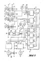
- Fig. 2 shows emergency stop switches 11 to 1n, which are connected to an electronic control system for a printing press.
- the latter consists of an input / output unit 4, a computing unit 5 and power units 6, 7, which are assigned to motors 61, 71.
- the power units essentially correspond to the main drive electronics 6 and the auxiliary drive electronics 7 (FIG. 1).
- FIG. 1 For the sake of clarity, only two motors, namely the motor 61 of the main drive and a motor 71 of an auxiliary drive, have been shown, although pressure measure machines can have significantly more motors.
- the design of the electronic control system in detail is possible in a variety of ways without departing from the scope of the invention.
- the input / output unit 4 comprises two input / output cards 41, 42, each of which has a multiplicity of inputs and outputs 43, 44.
- the input / output cards 41, 42 are connected to one another and to the input / output control card 51, which contains the monitoring circuit, among other things, of the computing unit via a bus system 45.
- the computer unit 5 also includes a memory card 54 for storing data, for example data from the printing press and data from the jobs to be processed.
- a memory card 54 for storing data, for example data from the printing press and data from the jobs to be processed.
- non-volatile memories are provided on the memory card 54.
- the programs themselves were stored in read-only memories which are arranged on the cards of the computers 52 and 53.
- a bus system 55 connects the input / output controller 51, the computers 52, 53 and the memory card 54.
- the input / output unit 4 is provided for binary signals (for example, switch closed, switch open; relays attract, relays drop out), digital signals are output which are used to control the power units 6, 7 and thus of the motors 61, 71 are used via the input / output control 51.
- the input / output control 51 is also supplied with a signal corresponding to the machine speed by a tachometer 9.
- An electromagnet 63 for releasing the brake is supplied with operating voltage supplied at 66 via two contacts 64, 65 of two contactors 67, 68.
- the contacts 64, 65 are designed as working contacts, so that the brake is only released when both contacts 64, 65 are closed, which in turn is only the case when both contactors 67, 68 from the input / output unit 4 with Voltage are supplied.
- the emergency switches of which only the emergency switches 11, 12, 13 and 1n are shown for the sake of clarity, can be provided with mushroom push buttons. However, other actuating devices, such as levers, tread strips and switches, which are actuated when protective guards are opened, can also be provided.
- Each of the emergency switches 11 to 1n has two contact pairs 21 to 2n, 31 to 3n working as a normally closed contact.
- the respective first contact pairs 21 to 2n are connected in series and connect a connection 1 provided with mains voltage to the primary winding 81 Transformer.
- a rectifier 83 is connected to the secondary winding 82 of the transformer. There is thus a galvanic separation between the safety circuit formed by the series connection of the respective first contact pairs and the primary winding 81 and the subsequent circuits. In addition, the switching voltage is reduced to a value suitable for controlling semiconductor circuits, while the voltage supplying the safety circuit has a sufficiently large value to ensure safe current flow despite the series connection of many contact pairs.
- Corresponding inputs of the power units 6, 7, the computers 52, 53 and the input / output controller 51 are connected to the safety circuit via a contactor 84.
- the respective second contact pairs 31 to 3n of the emergency switches 11 to 1n are connected to inputs of the input / output unit 4 of the electronic control system.
- the printing press is nevertheless operated via the stopped by the respective first contacts 11 to 1n, the transformer 81, 82, the rectifier 83 and the protection 84 safety circuit.
- the braking device 60 Only when the electronic control device is unable to stop the printing press by means of electrical braking, is the braking device 60 actuated, as described in connection with FIG. 1.
- the contactors 67, 68 are de-energized, whereby the magnetic coil 63 is separated from the operating voltage supplied at 66 with the aid of the contacts 64, 65. 2, the control of the contactors 67, 68 takes place via the input / output unit 4, but two separate output circuits are provided for the contactors 67, 68 to ensure a high level of security.
- switches 85, 86 can be connected to inputs of the input / output unit 4. These switches can be used to call up programs which result in a targeted shutdown of the printing press in accordance with the respective situation.
Landscapes
- Engineering & Computer Science (AREA)
- Mechanical Engineering (AREA)
- Inking, Control Or Cleaning Of Printing Machines (AREA)
Applications Claiming Priority (2)
| Application Number | Priority Date | Filing Date | Title |
|---|---|---|---|
| DE3614979A DE3614979C3 (de) | 1986-05-02 | 1986-05-02 | Sicherheitssystem für eine Druckmaschine |
| DE3614979 | 1986-05-02 |
Publications (4)
| Publication Number | Publication Date |
|---|---|
| EP0243728A2 true EP0243728A2 (fr) | 1987-11-04 |
| EP0243728A3 EP0243728A3 (en) | 1989-08-30 |
| EP0243728B1 EP0243728B1 (fr) | 1992-03-18 |
| EP0243728B2 EP0243728B2 (fr) | 1995-12-13 |
Family
ID=6300079
Family Applications (1)
| Application Number | Title | Priority Date | Filing Date |
|---|---|---|---|
| EP87104965A Expired - Lifetime EP0243728B2 (fr) | 1986-05-02 | 1987-04-03 | Système de sécurité pour une machine à imprimer |
Country Status (5)
| Country | Link |
|---|---|
| US (1) | US4951567A (fr) |
| EP (1) | EP0243728B2 (fr) |
| JP (1) | JPS62271745A (fr) |
| CA (1) | CA1286021C (fr) |
| DE (2) | DE3614979C3 (fr) |
Cited By (9)
| Publication number | Priority date | Publication date | Assignee | Title |
|---|---|---|---|---|
| EP0644050A1 (fr) * | 1993-08-19 | 1995-03-22 | MAN Roland Druckmaschinen AG | Dispositif de contrôle pour une machine à imprimer |
| EP0726643A1 (fr) * | 1995-02-08 | 1996-08-14 | MAN Roland Druckmaschinen AG | Méthode et appareil de freinage d'un entraînement principal pour machine d'impression |
| WO1996029204A1 (fr) * | 1995-03-18 | 1996-09-26 | Koenig & Bauer-Albert Ag | Procede d'actionnement d'une unite, par ex. une plieuse de presse rotative |
| FR2734513A1 (fr) * | 1995-05-22 | 1996-11-29 | Heidelberg Harris Sa | Procede de detection de perturbations dans le transport d'une nappe continue de papier dans une machine a imprimer |
| EP0978380A3 (fr) * | 1998-08-05 | 2000-05-31 | MAN Roland Druckmaschinen AG | Organe de calcul pour une machine à imprimer |
| EP1275499A3 (fr) * | 1995-03-18 | 2003-09-03 | Koenig & Bauer Aktiengesellschaft | Procédé d'actionnement d'une unité, par exemple une plieuse de presse rotative |
| US6725773B2 (en) | 2000-01-20 | 2004-04-27 | Man Roland Druckmaschinen Ag | Monitoring device for printer |
| EP1618441A1 (fr) * | 2003-04-25 | 2006-01-25 | Focke & Co. (GmbH & Co. KG) | Procede et dispositif de commande d'une unite de fabrication |
| EP3254852A1 (fr) * | 2016-06-07 | 2017-12-13 | Heidelberger Druckmaschinen AG | Imprimante ayant des cylindres à entraînement individuel par moteur électrique |
Families Citing this family (33)
| Publication number | Priority date | Publication date | Assignee | Title |
|---|---|---|---|---|
| JPS63137846A (ja) * | 1986-12-01 | 1988-06-09 | Komori Printing Mach Co Ltd | 印刷機械の制御装置 |
| DE3811046C2 (de) * | 1988-03-31 | 1994-05-26 | Heidelberger Druckmasch Ag | Verfahren und Vorrichtung zur Bestimmung des Übersetzungsverhältnisses an einer Druckmaschine |
| DE3843966A1 (de) * | 1988-12-24 | 1990-06-28 | Heidelberger Druckmasch Ag | Einrichtung zum ankoppeln von zusatzgeraeten |
| JPH03177257A (ja) * | 1989-12-04 | 1991-08-01 | Tokyo Kikai Seisakusho Ltd | ウェブ料紙案内装置 |
| DE4013106C1 (fr) * | 1990-04-25 | 1991-12-12 | Man Roland Druckmaschinen Ag, 6050 Offenbach, De | |
| DE4106901C2 (de) * | 1991-03-05 | 1994-05-26 | Kotterer Grafotec | Verfahren und Vorrichtung zur Überwachung einer Bahn |
| DE4202722B4 (de) * | 1992-01-31 | 2005-09-29 | Heidelberger Druckmaschinen Ag | Sicherheitseinrichtung für Regelungen oder Steuerungen von Antriebseinheiten einer Druckmaschine |
| DE4232559C2 (de) * | 1992-09-29 | 1994-07-28 | Roland Man Druckmasch | Vorrichtung und Verfahren zum registerhaltigen Kuppeln einer Rollenrotationsdruckmaschine |
| DE4241807A1 (de) * | 1992-12-11 | 1994-06-16 | Heidelberger Druckmasch Ag | Antrieb für eine Druckmaschine |
| DE4327972C1 (de) * | 1993-08-19 | 1994-10-20 | Herlan & Co Maschf | Verfahren zum Steuern des Anhaltens eines Druckwerkes einer Tuben- bzw. Dosenbedruckmaschine |
| DE4413047C2 (de) * | 1994-04-15 | 1996-04-18 | Roland Man Druckmasch | Verfahren und Vorrichtung zur Bremsüberwachung des Gleichstrommotors einer Druckmaschine |
| US6644184B1 (en) | 1995-02-09 | 2003-11-11 | Man Roland Druckmaschinen Ag | Offset printing machine |
| DE4430693B4 (de) * | 1994-08-30 | 2005-12-22 | Man Roland Druckmaschinen Ag | Antriebe für eine Rollenrotations-Offsetdruckmaschine |
| DE19520918C2 (de) * | 1995-06-08 | 1998-02-26 | Roland Man Druckmasch | Steuerung für eine Druckmaschine |
| DE19520919C2 (de) * | 1995-06-08 | 1998-02-26 | Roland Man Druckmasch | Steuerung für eine Druckmaschine |
| DE19520642C1 (de) * | 1995-06-09 | 1996-12-05 | Roland Man Druckmasch | Verfahren zum Steuern eines Mehrmotorenantriebs einer Druckmaschine sowie entsprechende Steuerung |
| DE19529430C2 (de) * | 1995-07-06 | 2000-07-13 | Baumueller Nuernberg Gmbh | Elektrisches Antriebssystem zur Verstellung von mehreren dreh- und/oder verschwenkbaren Funktionsteilen |
| DE19536918C1 (de) * | 1995-10-04 | 1997-01-30 | Roland Man Druckmasch | Überwachungseinrichtung für den Antrieb einer Druckmaschine |
| US5732637A (en) * | 1995-10-24 | 1998-03-31 | Virco Mfg. Corporation | Lightweight plastic furniture |
| DE19643252C2 (de) * | 1996-10-19 | 1999-05-20 | Roland Man Druckmasch | Steuerung für den Betrieb einer Druckmaschine |
| JP3037650B2 (ja) * | 1997-10-29 | 2000-04-24 | 株式会社東京機械製作所 | 輪転機の印刷ユニットの駆動装置 |
| JP4041569B2 (ja) * | 1997-12-26 | 2008-01-30 | クラリオン株式会社 | ディスクプレーヤ |
| DE10141590C5 (de) | 2000-09-19 | 2018-05-03 | Heidelberger Druckmaschinen Ag | Einrichtung zur Steuerung einer Druckmaschine |
| DE10120238B4 (de) * | 2001-04-19 | 2006-07-06 | Dr. Johannes Heidenhain Gmbh | Betätigungseinrichtung |
| DE20117222U1 (de) | 2001-10-24 | 2002-01-17 | Siemens AG, 80333 München | Produktionsmaschine mit einem Antriebsverband bestehend aus Antriebssektionen |
| DE10227241A1 (de) * | 2002-06-19 | 2004-01-15 | Koenig & Bauer Ag | Steuerung für Rotationsdruckmaschinen |
| DE10254608B4 (de) * | 2002-11-22 | 2010-12-02 | Siemens Ag | Antriebssystem |
| US7453677B2 (en) * | 2004-10-06 | 2008-11-18 | Teknic, Inc. | Power and safety control hub |
| DE102006053027A1 (de) * | 2006-11-10 | 2008-05-15 | Man Roland Druckmaschinen Ag | Verfahren zum Betreiben einer Druckmaschine |
| FR2910374B1 (fr) * | 2006-12-22 | 2009-04-03 | Goss Int Montataire Sa | Procede de commande d'une presse rotative et presse rotative |
| FR2910373B1 (fr) * | 2006-12-22 | 2009-04-03 | Goss Int Montataire Sa | Procede de commande d'une presse rotative et presse rotative |
| DE102007033432A1 (de) * | 2007-07-18 | 2009-01-22 | Heidelberger Druckmaschinen Ag | Druckmaschine mit elektrischem Quetschschutz |
| ES2820648T3 (es) * | 2017-09-29 | 2021-04-21 | Siemens Energy Global Gmbh & Co Kg | Procedimiento y dispositivo de bobinado de una máquina para fabricar papel |
Family Cites Families (9)
| Publication number | Priority date | Publication date | Assignee | Title |
|---|---|---|---|---|
| DE378616C (de) * | 1922-05-11 | 1923-07-21 | Walter Nowak | Vorrichtung zum Stillsetzen und Bremsen elektrisch angetriebener Druckmaschinen oder anderer Maschinen beim Reissen einer Papierbahn oder eines seilartigen Warenstranges |
| DE1110658B (de) * | 1959-06-03 | 1961-07-13 | Planeta Veb Druckmasch Werke | Schaltungsanordnung an Bogenrotations-Offsetdruckmaschinen |
| DE1098258B (de) * | 1959-10-14 | 1961-01-26 | Maschf Augsburg Nuernberg Ag | Sicherheitsvorrichtung zur Drehzahlueberwachung einer Welle |
| US3183423A (en) * | 1961-09-22 | 1965-05-11 | Square D Co | Limit control for motors |
| US3296512A (en) * | 1963-10-23 | 1967-01-03 | Westinghouse Electric Corp | Controlled braking system for load lifting apparatus |
| GB1276843A (en) * | 1968-08-28 | 1972-06-07 | Antoma Hairdressing Company Lt | Improvements in or relating to uprintin machines |
| DD226708B1 (de) * | 1984-09-03 | 1989-07-05 | Medizin Labortechnik Veb K | Schaltungsanordnung zur zuverlaessigkeitsueberwachung von drehzahlimpulsen |
| DE3447090A1 (de) * | 1984-12-22 | 1986-06-26 | Heidelberger Druckmaschinen Ag, 6900 Heidelberg | Verfahren und einrichtung zur bremsenkontrolle eines bewegungsueberwachten und -gesteuerten antriebsmotors in einer druckmaschine |
| US4643091A (en) * | 1985-11-25 | 1987-02-17 | Ncr Corporation | Electromagnetic clutch-brake positioning assembly |
-
1986
- 1986-05-02 DE DE3614979A patent/DE3614979C3/de not_active Expired - Fee Related
-
1987
- 1987-03-11 CA CA000531408A patent/CA1286021C/fr not_active Expired - Lifetime
- 1987-04-03 DE DE8787104965T patent/DE3777437D1/de not_active Expired - Lifetime
- 1987-04-03 EP EP87104965A patent/EP0243728B2/fr not_active Expired - Lifetime
- 1987-05-01 JP JP62106486A patent/JPS62271745A/ja active Pending
-
1989
- 1989-07-07 US US07/376,937 patent/US4951567A/en not_active Expired - Lifetime
Cited By (13)
| Publication number | Priority date | Publication date | Assignee | Title |
|---|---|---|---|---|
| EP0644050A1 (fr) * | 1993-08-19 | 1995-03-22 | MAN Roland Druckmaschinen AG | Dispositif de contrôle pour une machine à imprimer |
| EP0726643A1 (fr) * | 1995-02-08 | 1996-08-14 | MAN Roland Druckmaschinen AG | Méthode et appareil de freinage d'un entraînement principal pour machine d'impression |
| EP1666248A1 (fr) * | 1995-03-18 | 2006-06-07 | Koenig & Bauer Aktiengesellschaft | Procédé d'actionnement d'une unité, par exemple une plieuse de presse rotative |
| WO1996029204A1 (fr) * | 1995-03-18 | 1996-09-26 | Koenig & Bauer-Albert Ag | Procede d'actionnement d'une unite, par ex. une plieuse de presse rotative |
| EP1275499A3 (fr) * | 1995-03-18 | 2003-09-03 | Koenig & Bauer Aktiengesellschaft | Procédé d'actionnement d'une unité, par exemple une plieuse de presse rotative |
| FR2734513A1 (fr) * | 1995-05-22 | 1996-11-29 | Heidelberg Harris Sa | Procede de detection de perturbations dans le transport d'une nappe continue de papier dans une machine a imprimer |
| EP0978380A3 (fr) * | 1998-08-05 | 2000-05-31 | MAN Roland Druckmaschinen AG | Organe de calcul pour une machine à imprimer |
| US6725773B2 (en) | 2000-01-20 | 2004-04-27 | Man Roland Druckmaschinen Ag | Monitoring device for printer |
| EP1618441A1 (fr) * | 2003-04-25 | 2006-01-25 | Focke & Co. (GmbH & Co. KG) | Procede et dispositif de commande d'une unite de fabrication |
| US7298111B2 (en) | 2003-04-25 | 2007-11-20 | Focke & Co. (Gmbh & Co. Kg) | Method and device for controlling a production unit |
| EP3254852A1 (fr) * | 2016-06-07 | 2017-12-13 | Heidelberger Druckmaschinen AG | Imprimante ayant des cylindres à entraînement individuel par moteur électrique |
| CN107672291A (zh) * | 2016-06-07 | 2018-02-09 | 海德堡印刷机械股份公司 | 具有被单独驱动的滚筒的印刷机 |
| CN107672291B (zh) * | 2016-06-07 | 2020-10-16 | 海德堡印刷机械股份公司 | 具有被单独驱动的滚筒的印刷机 |
Also Published As
| Publication number | Publication date |
|---|---|
| US4951567A (en) | 1990-08-28 |
| JPS62271745A (ja) | 1987-11-26 |
| DE3777437D1 (de) | 1992-04-23 |
| DE3614979C2 (de) | 1994-02-10 |
| DE3614979C3 (de) | 1999-12-16 |
| DE3614979A1 (de) | 1987-11-05 |
| EP0243728B1 (fr) | 1992-03-18 |
| EP0243728B2 (fr) | 1995-12-13 |
| CA1286021C (fr) | 1991-07-09 |
| EP0243728A3 (en) | 1989-08-30 |
Similar Documents
| Publication | Publication Date | Title |
|---|---|---|
| EP0243728B1 (fr) | Système de sécurité pour une machine à imprimer | |
| DE4334260C2 (de) | Steuervorrichtung für ein Fahrzeug mit einer Antiblockier-Bremseinrichtung und einer Servolenkeinrichtung | |
| EP0577641B1 (fr) | Circuit pour regulateur | |
| EP0187247B1 (fr) | Procédé et dispositif pour régler le freinage d'un moteur d'entraînement dans une machine à imprimer | |
| EP0780276A2 (fr) | Dispositif de freinage pour un véhicule | |
| DE1538493B2 (de) | Verfahren und Schaltungsanordnunge zur direkten digitalen Regelung | |
| DE19509150C2 (de) | Verfahren zum Steuern und Regeln von Fahrzeug-Bremsanlagen sowie Fahrzeug-Bremsanlage | |
| EP3704048B1 (fr) | Dispositif de surveillance de sécurité destiné à surveiller des conditions relatives à la sécurité dans une installation de transport de personnes ainsi que procédé de fonctionnement d'un tel dispositif | |
| DE69916772T2 (de) | Steuervorrichtung eine automatischen Maschine | |
| EP0052759A2 (fr) | Dispositif dans un poste électronique d'aguillage pour l'alimentation et le télécontrôle de la commande d'aiguilles | |
| DE2848358C2 (de) | Störungsüberwachungsanordnung für eine Doppelventil-Einheit in einer pneumatischen Schaltung | |
| EP0153900B1 (fr) | Commande et protection d'un servo-aiguillage avec un dispositif de télécommande ou de commande local | |
| DE3428215A1 (de) | Anordnung zum ueberwachen einer speicherprogrammierbaren steuereinrichtung | |
| DE3522220C2 (de) | Schaltungsanordnung zur sicheren Ansteuerung von Stellelementen eines Prozesses | |
| WO2005021347A1 (fr) | Dispositif de freinage de secours et systeme de freinage pour vehicule ferroviaire, et procede permettant de sauvegarder une fonction de freinage de secours dans des vehicules ferroviaires | |
| DE69212373T2 (de) | Regelung des Kupplungs-Bremsantriebes einer Presse | |
| EP0243620B1 (fr) | Dispositif de commande pour le blocage d'un différentiel avec un élément de manoeuvre | |
| DE69614238T2 (de) | Zweihand-Steuerschaltung für Pressen | |
| DE10254608B4 (de) | Antriebssystem | |
| DE3919558C2 (fr) | ||
| DE102019113753A1 (de) | Notbremsventilsystem für ein pneumatisches Bremssystem | |
| EP0389416A1 (fr) | Système de frein pour véhicule sur rails, en particulier pour chemin de fer à crémaillère | |
| DE69614987T2 (de) | Steuereinrichtung eines Doppelventils | |
| AT395358B (de) | Datenverarbeitungsanlage mit in mehreren kanaelen dieselben daten verarbeitenden rechnern | |
| EP1176508B1 (fr) | Dispositif visant la surveillance du bon fonctionnement de composants exécutant la même action ou des actions correspondantes dans un système électrique |
Legal Events
| Date | Code | Title | Description |
|---|---|---|---|
| PUAI | Public reference made under article 153(3) epc to a published international application that has entered the european phase |
Free format text: ORIGINAL CODE: 0009012 |
|
| 17P | Request for examination filed |
Effective date: 19870403 |
|
| AK | Designated contracting states |
Kind code of ref document: A2 Designated state(s): CH DE FR GB IT LI NL SE |
|
| PUAL | Search report despatched |
Free format text: ORIGINAL CODE: 0009013 |
|
| AK | Designated contracting states |
Kind code of ref document: A3 Designated state(s): CH DE FR GB IT LI NL SE |
|
| 17Q | First examination report despatched |
Effective date: 19910313 |
|
| GRAA | (expected) grant |
Free format text: ORIGINAL CODE: 0009210 |
|
| AK | Designated contracting states |
Kind code of ref document: B1 Designated state(s): CH DE FR GB IT LI NL SE |
|
| PGFP | Annual fee paid to national office [announced via postgrant information from national office to epo] |
Ref country code: SE Payment date: 19920414 Year of fee payment: 6 |
|
| REF | Corresponds to: |
Ref document number: 3777437 Country of ref document: DE Date of ref document: 19920423 |
|
| PGFP | Annual fee paid to national office [announced via postgrant information from national office to epo] |
Ref country code: NL Payment date: 19920430 Year of fee payment: 6 |
|
| ITF | It: translation for a ep patent filed | ||
| GBT | Gb: translation of ep patent filed (gb section 77(6)(a)/1977) | ||
| ET | Fr: translation filed | ||
| PLBI | Opposition filed |
Free format text: ORIGINAL CODE: 0009260 |
|
| 26 | Opposition filed |
Opponent name: MAN ROLAND DRUCKMASCHINEN AG Effective date: 19921216 |
|
| NLR1 | Nl: opposition has been filed with the epo |
Opponent name: MAN ROLAND DRUCKMASCHINEN AG |
|
| PG25 | Lapsed in a contracting state [announced via postgrant information from national office to epo] |
Ref country code: SE Effective date: 19930404 |
|
| PG25 | Lapsed in a contracting state [announced via postgrant information from national office to epo] |
Ref country code: NL Effective date: 19931101 |
|
| NLV4 | Nl: lapsed or anulled due to non-payment of the annual fee | ||
| EUG | Se: european patent has lapsed |
Ref document number: 87104965.6 Effective date: 19931110 |
|
| PUAH | Patent maintained in amended form |
Free format text: ORIGINAL CODE: 0009272 |
|
| STAA | Information on the status of an ep patent application or granted ep patent |
Free format text: STATUS: PATENT MAINTAINED AS AMENDED |
|
| 27A | Patent maintained in amended form |
Effective date: 19951213 |
|
| AK | Designated contracting states |
Kind code of ref document: B2 Designated state(s): CH DE FR GB IT LI NL SE |
|
| REG | Reference to a national code |
Ref country code: CH Ref legal event code: AEN Free format text: AUFRECHTERHALTUNG DES PATENTES IN GEAENDERTER FORM |
|
| ET3 | Fr: translation filed ** decision concerning opposition | ||
| GBTA | Gb: translation of amended ep patent filed (gb section 77(6)(b)/1977) |
Effective date: 19960313 |
|
| PGFP | Annual fee paid to national office [announced via postgrant information from national office to epo] |
Ref country code: CH Payment date: 19980518 Year of fee payment: 12 |
|
| PG25 | Lapsed in a contracting state [announced via postgrant information from national office to epo] |
Ref country code: LI Free format text: LAPSE BECAUSE OF NON-PAYMENT OF DUE FEES Effective date: 19990430 Ref country code: CH Free format text: LAPSE BECAUSE OF NON-PAYMENT OF DUE FEES Effective date: 19990430 |
|
| REG | Reference to a national code |
Ref country code: CH Ref legal event code: PL |
|
| REG | Reference to a national code |
Ref country code: GB Ref legal event code: IF02 |
|
| PG25 | Lapsed in a contracting state [announced via postgrant information from national office to epo] |
Ref country code: IT Free format text: LAPSE BECAUSE OF NON-PAYMENT OF DUE FEES;WARNING: LAPSES OF ITALIAN PATENTS WITH EFFECTIVE DATE BEFORE 2007 MAY HAVE OCCURRED AT ANY TIME BEFORE 2007. THE CORRECT EFFECTIVE DATE MAY BE DIFFERENT FROM THE ONE RECORDED. Effective date: 20050403 |
|
| PGFP | Annual fee paid to national office [announced via postgrant information from national office to epo] |
Ref country code: FR Payment date: 20050419 Year of fee payment: 19 |
|
| PGFP | Annual fee paid to national office [announced via postgrant information from national office to epo] |
Ref country code: DE Payment date: 20050427 Year of fee payment: 19 |
|
| PGFP | Annual fee paid to national office [announced via postgrant information from national office to epo] |
Ref country code: GB Payment date: 20060410 Year of fee payment: 20 |
|
| PG25 | Lapsed in a contracting state [announced via postgrant information from national office to epo] |
Ref country code: DE Free format text: LAPSE BECAUSE OF NON-PAYMENT OF DUE FEES Effective date: 20061101 |
|
| REG | Reference to a national code |
Ref country code: FR Ref legal event code: ST Effective date: 20061230 |
|
| PG25 | Lapsed in a contracting state [announced via postgrant information from national office to epo] |
Ref country code: GB Free format text: LAPSE BECAUSE OF EXPIRATION OF PROTECTION Effective date: 20070402 |
|
| REG | Reference to a national code |
Ref country code: GB Ref legal event code: PE20 |
|
| PG25 | Lapsed in a contracting state [announced via postgrant information from national office to epo] |
Ref country code: FR Free format text: LAPSE BECAUSE OF NON-PAYMENT OF DUE FEES Effective date: 20060502 |