EP3254852A1 - Imprimante ayant des cylindres à entraînement individuel par moteur électrique - Google Patents
Imprimante ayant des cylindres à entraînement individuel par moteur électrique Download PDFInfo
- Publication number
- EP3254852A1 EP3254852A1 EP17169859.0A EP17169859A EP3254852A1 EP 3254852 A1 EP3254852 A1 EP 3254852A1 EP 17169859 A EP17169859 A EP 17169859A EP 3254852 A1 EP3254852 A1 EP 3254852A1
- Authority
- EP
- European Patent Office
- Prior art keywords
- subsystems
- processing machine
- drive
- substrate processing
- machine according
- Prior art date
- Legal status (The legal status is an assumption and is not a legal conclusion. Google has not performed a legal analysis and makes no representation as to the accuracy of the status listed.)
- Granted
Links
- 238000012544 monitoring process Methods 0.000 claims abstract description 30
- 238000012545 processing Methods 0.000 claims abstract description 15
- 239000000758 substrate Substances 0.000 claims abstract description 12
- 238000009826 distribution Methods 0.000 claims description 15
- 238000000034 method Methods 0.000 claims description 7
- 238000012937 correction Methods 0.000 claims description 5
- 230000002950 deficient Effects 0.000 claims description 4
- 238000004804 winding Methods 0.000 abstract description 15
- 238000011161 development Methods 0.000 description 9
- 230000018109 developmental process Effects 0.000 description 9
- 239000000463 material Substances 0.000 description 4
- 238000013461 design Methods 0.000 description 3
- 238000004519 manufacturing process Methods 0.000 description 3
- 238000012546 transfer Methods 0.000 description 3
- 230000001419 dependent effect Effects 0.000 description 2
- 238000001514 detection method Methods 0.000 description 2
- 230000000694 effects Effects 0.000 description 2
- 230000001360 synchronised effect Effects 0.000 description 2
- 230000005540 biological transmission Effects 0.000 description 1
- 230000006735 deficit Effects 0.000 description 1
- 238000009827 uniform distribution Methods 0.000 description 1
Images

Classifications
-
- B—PERFORMING OPERATIONS; TRANSPORTING
- B41—PRINTING; LINING MACHINES; TYPEWRITERS; STAMPS
- B41F—PRINTING MACHINES OR PRESSES
- B41F13/00—Common details of rotary presses or machines
- B41F13/004—Electric or hydraulic features of drives
- B41F13/0045—Electric driving devices
-
- B—PERFORMING OPERATIONS; TRANSPORTING
- B41—PRINTING; LINING MACHINES; TYPEWRITERS; STAMPS
- B41F—PRINTING MACHINES OR PRESSES
- B41F33/00—Indicating, counting, warning, control or safety devices
- B41F33/04—Tripping devices or stop-motions
- B41F33/12—Tripping devices or stop-motions for starting or stopping the machine as a whole
-
- B—PERFORMING OPERATIONS; TRANSPORTING
- B41—PRINTING; LINING MACHINES; TYPEWRITERS; STAMPS
- B41P—INDEXING SCHEME RELATING TO PRINTING, LINING MACHINES, TYPEWRITERS, AND TO STAMPS
- B41P2213/00—Arrangements for actuating or driving printing presses; Auxiliary devices or processes
- B41P2213/10—Constitutive elements of driving devices
- B41P2213/11—Motors
- B41P2213/124—Electric motors
- B41P2213/126—Rotary electric motors
Definitions
- the present invention relates to a sheet-fed printing machine with individually driven cylinders, wherein the individual drives used for improved collision avoidance between the individually driven cylinders have a galvanically separated double winding.
- the invention is in the technical field of sheet-fed printing machines.
- the classic drive type consists of a common engine that drives several cylinders, which are coupled together via a corresponding Zahnradzug to ensure uniform power transmission from the engine to the individual cylinders.
- a high manufacturing cost is required to achieve a corresponding angular accuracy, which ensures that the individual cylinders are driven synchronously.
- German patent DE 101 22 906 C1 therefore discloses a structure switching for speed control in case of failure.
- this method it is provided to use the faulty drive as a guide value for shutting down the printing press.
- the actual value of the faulty drive is thus used as a setpoint for shutting down the other individual drives.
- the disadvantage here is that the faulty axis is switched off after error detection and a more accurate course of the spill is therefore not predictable.
- a collision can also be caused by a jammed sheet.
- torque-forming currents are possible in the case of short circuits in power electronics, which influence the motor in an uncontrolled manner. There is the danger that the intact drives can not follow the faulty drive, resulting in additional angular deviations and collision possibilities.
- An inventive solution to this problem is a printing material processing machine with individually driven cylinders, wherein the electric motor of each individual drive consists of at least two subsystems and which is characterized in that the at least two subsystems consist of at least two galvanically separated, parallel double windings, at least one Current controller for both subsystems is present, both subsystems have their own control and weighted by a computer-aided monitoring and control logic are controlled.
- the solution of the problem is thus achieved in that each individual drive for the corresponding cylinder consists of at least two subsystems.
- the subsystems each have their own control and can thus be controlled separately from the computer-aided monitoring logic.
- the weighting of the power distribution between the individual subsystems is carried out by the monitoring and control logic, wherein the at least one current regulator regulates the full power for all subsystems, the distribution or weighting but the monitoring and control logic takes over.
- the at least one current regulator regulates the full power for all subsystems, the distribution or weighting but the monitoring and control logic takes over.
- the individually driven cylinder is driven by at least two on the torque plane parallel and angle synchronous drives. If one drive or power electronics fails, the cylinder remains controllable. The monitoring of the drives takes place in each case on the torque level, so that an effect on the speed or the angular position of the cylinder is avoided.
- a preferred development of the printing machine according to the invention is that it involves two subsystems that have a common current regulator or each have their own current regulator. It is preferred for the printing press according to the invention that two subsystems are used by means of two galvanically separated double windings. There is both the possibility that a common current controller corrects the two subsystems, as well as that each subsystem has its own, separate current regulator.
- a further preferred development of the printing press according to the invention is that the two subsystems consist of two separate stator packs on one axis, while they have a common rotor.
- An alternative embodiment of the single drive motor with two subsystems to the two galvanically isolated parallel double windings is the execution of the engine with two separate stator packs.
- a further preferred development of the printing press according to the invention is that the two subsystems consist of two separate drives on one axis.
- the advantage of using two separate and separate drives on one axis is that the two subsystems can operate almost completely independently of each other, as they have few common components. In this embodiment, therefore, the two subsystems have separate rotors.
- a further preferred development of the printing press according to the invention is that a symmetrical distribution of the torque between the two subsystems is effected by the monitoring and control logic. By a symmetrical distribution of the torque between the two subsystems, a more accurate monitoring of the drive process can be realized.
- a further preferred development of the printing press according to the invention is that the computer-aided monitoring and control logic ensures the current symmetry by comparing the current actual values.
- the symmetrical distribution of the torque between the two subsystems is thereby ensured by the current controller converts a fixed to him fixed current setpoint to both subsystems.
- the predetermined current setpoint may be e.g. be predetermined by the computer-aided monitoring logic.
- the two current actual values which are present at both subsystems are compared in order to be able to intervene in the event of a fault, that is to say for deviating current actual values. This is done by an active device, e.g. from the computer-aided monitoring logic.
- a further preferred development of the printing press according to the invention is that the computer-aided monitoring and control logic is set up in such a way that it additionally compares the current actual values with a reference value and switches off the subsystem which outputs a value deviating from the reference value.
- the task of the computer-aided monitoring logic is not only to ensure the current balance, but also in case of failure, that is, if the two current actual values differ from each other or from a predetermined reference value, the defective subsystem, which provides a different current actual value accordingly off.
- a further preferred development of the printing press according to the invention is that a phase correction is performed on the second subsystem by means of an offset for the position angle of the motor determined by a rotation angle actual value measuring device. Since the two subsystems are realized by means of different double windings, which can not be aligned absolutely exactly to each other, it is necessary the resulting deviations of the phase angle of the motor by an offset compensate. This offset is added digitally to the value of the measured value determined by the angle of rotation actual value measuring device.
- a further solution according to the invention of the object is disclosed by a method for collision avoidance in a printing material processing machine according to one of claims 1 to 8, which is characterized in that the computer-aided monitoring logic monitors the two subsystems of the single drive and in case of failure of a partial drive the single drive over the own control with common current regulator of the still working partial drive switches off in an orderly manner.
- the computer-aided monitoring logic monitors the two subsystems of the single drive and in case of failure of a partial drive the single drive over the own control with common current regulator of the still working partial drive switches off in an orderly manner.
- the computer-aided monitoring logic shuts down the entire individual drive in an orderly manner by means of the separate control of the still functioning, at least one other partial drive.
- the controls of the still functioning, at least one sub-drive and the faulty sub-drive must be coordinated with each other so that there is a collision-free shutdown of the individual drive of the corresponding cylinder.
- Another solution to the problem posed is a method for collision avoidance in a printing material processing machine according to one of claims 1 to 9, which is characterized in that computer-aided monitoring and control logic monitors the subsystems of the individual drive and in the event of a fault partial drive the computer-aided monitoring - And control logic by means of the information about the disturbed part of drive performs a recalculation of the power distribution and thus over the other, still functioning at least one partial drive compensates for the error of the disturbed part drive.
- the monitoring logic recalculates the current distribution and thus the distribution of torque between the subsystems, which then no longer with one symmetrical distribution of torque between the sub-drives of the still functioning, at least one partial drive compensates for the fault of the faulty partial drive and as a result the single drive can continue to be operated.
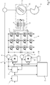
- FIG. 1 the anti-collision system of the printing press according to the invention is described in its structural design.
- an engine 12 of the individual drive drives the correspondingly assigned cylinder 13, wherein the angular position of the cylinder 13 is fed back to the system via a rotation-angle actual-value measuring device.
- the electric motor 12 consists of a design with galvanically separated parallel double windings 9, 10. These are controlled separately by two separate inverters 7, 8 separated from each other.
- the drive control is shown schematically.
- the symmetrical distribution of the torque on the two subsystems 6, 19 of the individual drive is implemented by a common current regulator 2, which controls both the torque-forming portion of the current Iq, and the magnetizing current component Id.
- a speed sensor 1 is a target speed value for the electric motor 12 of the cylinder to be driven 13 before.
- the dependent current setpoint for both subsystems then becomes from a common current controller 2 symmetrically distributed to the two subsystems of the individual drive 6, 19.
- Two ammeters 4, 5 measure the applied actual current values and report them back to the common current controller 2.
- phase correction is present, which can act on one of the two subsystems 6, 19 in order to additionally effect a correction of the angular position of the cylinder 13 determined by the rotational angle actual value measuring device.
- a computer-based monitoring logic 3 checks via the two two ammeters 4, 5 whether the current actual values of the two subsystems 6, 19 are distributed approximately equally in each case according to the symmetrical distribution to 50% each. If these deviate from the desired uniform distribution, or deviate from a respectively preset reference value, the monitoring logic 3 initiates an orderly shutdown of the subsystem of the individual drive, which generates the deviating value. If the faulty subsystem has been switched off, the entire drive system of all relevant individual drives of the printing press is slowly shut down without collision. In this case, the defective sub-drive is locked accordingly and the intact sub-drive is continued to operate adjusted to shutdown of the overall system.
- the other intact subsystem is controlled by the monitoring logic 3 in such a way that the fault of the disturbed subsystem can be compensated thereby.
- the monitoring logic 3 it is necessary that both information about the current distribution of the intact subsystem, as well as the faulty subsystem are queried and this information in the recalculation of the power distribution, which is necessary for compensation, are included. This is implemented by recalculating the current phasors, which are identical in both systems in the undisturbed system. In this operating mode, the entire system of all individual drives then continues to operate and the press is not shut down.
- FIG. 2b an alternative embodiment of the separate drive when using two separate stator packs 16, 17 shown on an axis.
- w1 and w2 which correspond to the stator packs but have a common axis and a common rotor 15.
- FIG. 2 c shows a further alternative embodiment of the individual drive consisting of two subsystems 6, 19.
- the stator is divided into two halves, but also the rotor 15.
- This embodiment thus corresponds to the use of two separate drives on one axis. It has the advantage that standard components can be used.
Landscapes
- Engineering & Computer Science (AREA)
- Mechanical Engineering (AREA)
- Inking, Control Or Cleaning Of Printing Machines (AREA)
- Control Of Multiple Motors (AREA)
Applications Claiming Priority (1)
| Application Number | Priority Date | Filing Date | Title |
|---|---|---|---|
| DE102016209989.2A DE102016209989A1 (de) | 2016-06-07 | 2016-06-07 | Druckmaschine mit einzeln angetriebenen Zylindern |
Publications (2)
| Publication Number | Publication Date |
|---|---|
| EP3254852A1 true EP3254852A1 (fr) | 2017-12-13 |
| EP3254852B1 EP3254852B1 (fr) | 2021-11-03 |
Family
ID=58672483
Family Applications (1)
| Application Number | Title | Priority Date | Filing Date |
|---|---|---|---|
| EP17169859.0A Active EP3254852B1 (fr) | 2016-06-07 | 2017-05-08 | Imprimante ayant des cylindres à entraînement individuel par moteur électrique |
Country Status (3)
| Country | Link |
|---|---|
| EP (1) | EP3254852B1 (fr) |
| CN (1) | CN107672291B (fr) |
| DE (1) | DE102016209989A1 (fr) |
Citations (12)
| Publication number | Priority date | Publication date | Assignee | Title |
|---|---|---|---|---|
| EP0000001B1 (fr) | 1977-09-02 | 1981-01-07 | Europäische Atomgemeinschaft (Euratom) | Pompe de chaleur thermique |
| EP0243728A2 (fr) * | 1986-05-02 | 1987-11-04 | Heidelberger Druckmaschinen Aktiengesellschaft | Système de sécurité pour une machine à imprimer |
| DE19600110A1 (de) * | 1995-08-10 | 1997-07-10 | Baumueller Nuernberg Gmbh | Elektrisches Antriebssystem und Sicherheitsmodul insbesondere in einer Druckmaschine |
| EP0904934B1 (fr) | 1997-09-26 | 2002-12-18 | Heidelberger Druckmaschinen Aktiengesellschaft | Dispositif et procédé d'entraínement des machines d'impression avec plussieurs moteurs indépendents |
| DE10122906C1 (de) | 2001-05-11 | 2003-01-09 | Siemens Ag | Verfahren zur Fehlerbehandlung und Schadensverhütung an Werkzeug- und Produktionsmaschinen, sowie Robotern |
| DE10255041A1 (de) * | 2001-12-27 | 2003-07-17 | Heidelberger Druckmasch Ag | Antrieb für einen umlaufenden Zylinder einer drucktechnischen Maschine |
| EP1609598A1 (fr) | 2004-06-22 | 2005-12-28 | Heidelberger Druckmaschinen Aktiengesellschaft | Procédé d'entrainement sécurisé d'une machine d'impression et machine d'impression mettant en oeuvre ce procédé |
| EP1640161A2 (fr) * | 2004-09-22 | 2006-03-29 | MAN Roland Druckmaschinen AG | Cylindre d'une machine à imprimer |
| WO2006134070A2 (fr) * | 2005-06-17 | 2006-12-21 | Koenig & Bauer Aktiengesellschaft | Machine d'impression flexographique |
| EP1736698A2 (fr) * | 2005-06-23 | 2006-12-27 | Koenig & Bauer Aktiengesellschaft | Dispositif pour raccorder un composant rotatif d'une machine d'impression pour transmettre du fluide sous pression |
| DE102007039915A1 (de) * | 2007-07-13 | 2009-01-15 | Wifag Maschinenfabrik Ag | Verfahren und Vorrichtung zum Stillsetzen einer Druckmaschine bei Netzausfall |
| DE102009033876A1 (de) * | 2008-08-07 | 2010-02-11 | Heidelberger Druckmaschinen Ag | Hilfsantrieb mit Schrittmotorbetrieb |
Family Cites Families (6)
| Publication number | Priority date | Publication date | Assignee | Title |
|---|---|---|---|---|
| DE102005032149A1 (de) * | 2005-06-22 | 2006-12-28 | Kba-Metronic Ag | Druckmaschine |
| US8497648B2 (en) * | 2008-05-30 | 2013-07-30 | Panasonic Corporation | Synchronous electric motor drive system |
| US8717788B2 (en) * | 2011-03-10 | 2014-05-06 | Ford Global Technologies, Llc | Method and system for controlling a power converter system connected to a DC-bus capacitor |
| DE102015117813A1 (de) * | 2014-10-21 | 2016-04-21 | Denso Corporation | Steuerungseinheit und Steuerungsverfahren für rotierende elektrische Maschine |
| CN105207542A (zh) * | 2015-10-27 | 2015-12-30 | 合肥工业大学 | 一种双绕组直流无刷电机冗余控制系统及其控制方法 |
| CN205142058U (zh) * | 2015-10-27 | 2016-04-06 | 合肥工业大学 | 一种双绕组直流无刷电机冗余控制系统 |
-
2016
- 2016-06-07 DE DE102016209989.2A patent/DE102016209989A1/de not_active Withdrawn
-
2017
- 2017-05-08 EP EP17169859.0A patent/EP3254852B1/fr active Active
- 2017-06-05 CN CN201710412816.9A patent/CN107672291B/zh active Active
Patent Citations (12)
| Publication number | Priority date | Publication date | Assignee | Title |
|---|---|---|---|---|
| EP0000001B1 (fr) | 1977-09-02 | 1981-01-07 | Europäische Atomgemeinschaft (Euratom) | Pompe de chaleur thermique |
| EP0243728A2 (fr) * | 1986-05-02 | 1987-11-04 | Heidelberger Druckmaschinen Aktiengesellschaft | Système de sécurité pour une machine à imprimer |
| DE19600110A1 (de) * | 1995-08-10 | 1997-07-10 | Baumueller Nuernberg Gmbh | Elektrisches Antriebssystem und Sicherheitsmodul insbesondere in einer Druckmaschine |
| EP0904934B1 (fr) | 1997-09-26 | 2002-12-18 | Heidelberger Druckmaschinen Aktiengesellschaft | Dispositif et procédé d'entraínement des machines d'impression avec plussieurs moteurs indépendents |
| DE10122906C1 (de) | 2001-05-11 | 2003-01-09 | Siemens Ag | Verfahren zur Fehlerbehandlung und Schadensverhütung an Werkzeug- und Produktionsmaschinen, sowie Robotern |
| DE10255041A1 (de) * | 2001-12-27 | 2003-07-17 | Heidelberger Druckmasch Ag | Antrieb für einen umlaufenden Zylinder einer drucktechnischen Maschine |
| EP1609598A1 (fr) | 2004-06-22 | 2005-12-28 | Heidelberger Druckmaschinen Aktiengesellschaft | Procédé d'entrainement sécurisé d'une machine d'impression et machine d'impression mettant en oeuvre ce procédé |
| EP1640161A2 (fr) * | 2004-09-22 | 2006-03-29 | MAN Roland Druckmaschinen AG | Cylindre d'une machine à imprimer |
| WO2006134070A2 (fr) * | 2005-06-17 | 2006-12-21 | Koenig & Bauer Aktiengesellschaft | Machine d'impression flexographique |
| EP1736698A2 (fr) * | 2005-06-23 | 2006-12-27 | Koenig & Bauer Aktiengesellschaft | Dispositif pour raccorder un composant rotatif d'une machine d'impression pour transmettre du fluide sous pression |
| DE102007039915A1 (de) * | 2007-07-13 | 2009-01-15 | Wifag Maschinenfabrik Ag | Verfahren und Vorrichtung zum Stillsetzen einer Druckmaschine bei Netzausfall |
| DE102009033876A1 (de) * | 2008-08-07 | 2010-02-11 | Heidelberger Druckmaschinen Ag | Hilfsantrieb mit Schrittmotorbetrieb |
Also Published As
| Publication number | Publication date |
|---|---|
| CN107672291B (zh) | 2020-10-16 |
| CN107672291A (zh) | 2018-02-09 |
| DE102016209989A1 (de) | 2017-12-07 |
| EP3254852B1 (fr) | 2021-11-03 |
Similar Documents
| Publication | Publication Date | Title |
|---|---|---|
| DE102006042038B3 (de) | Verfahren und Vorrichtung zur sicheren Drehmomentbegrenzung | |
| DE19520642C1 (de) | Verfahren zum Steuern eines Mehrmotorenantriebs einer Druckmaschine sowie entsprechende Steuerung | |
| EP0753405B1 (fr) | Dispositif d'entraínement à plusiers moteurs pour une machine à imprimer | |
| EP0223100B1 (fr) | Dispositif de commande pour un moteur d'entraînement électrique d'une machine à imprimer | |
| EP0814959A1 (fr) | Procede d'actionnement d'une unite, par ex. une plieuse de presse rotative | |
| DE102011119229A1 (de) | Korrekturverfahren für eine Position eines magnetischen Pols eines Motors | |
| WO2013182514A1 (fr) | Système de sécurité pour éolienne | |
| DE19600110A1 (de) | Elektrisches Antriebssystem und Sicherheitsmodul insbesondere in einer Druckmaschine | |
| EP0917954B1 (fr) | Dispositif et procédé pour produire un valeur de référence d'une position individuelle dans un procédé d'impression | |
| EP3963617B1 (fr) | Système d'entraînement conçu pour un commutateur et procédé pour entraîner un commutateur | |
| DE102016209442B4 (de) | Zusatzstromversorgungssystem und Betriebsverfahren dafür | |
| EP0223101B1 (fr) | Dispositif de commande pour un moteur d'entraînement à courant continu à excitation séparée et procédé pour commander un moteur d'entraînement à courant continu d'une machine à imprimer | |
| EP3254852B1 (fr) | Imprimante ayant des cylindres à entraînement individuel par moteur électrique | |
| DE102009039485B4 (de) | Regelungssystem und Verfahren zur Regelung eines Magnetlagers | |
| DE19716457C2 (de) | Steuerungsverfahren für ein elektrisches Antriebssystem zum synchronen Verstellen mehrerer bewegbarer Funktionsteile | |
| DE102006014526A1 (de) | Verfahren und Vorrichtung zur Reduzierung von periodischen Drehwinkel-Lagedifferenzen | |
| EP3182139A1 (fr) | Surveillance de la vitesse d'un entrainement avec protection contre les erreurs | |
| DE10018774B4 (de) | Verfahren und Schaltungsanordnung zum lagegeregelten Stillsetzen von rotierenden Bauteilen bei wellenlosen Antrieben bei Spannungsausfall | |
| DE102014019119A1 (de) | Antriebsvorrichtung für ein Kraftfahrzeug | |
| DE102007017285A1 (de) | Verfahren und Vorrichtung zum Überwachen von Drehstrommaschinen | |
| DE10124977A1 (de) | Antrieb für einen Zylinder einer Rotationsdruckmaschine | |
| DE3541275C2 (fr) | ||
| DE112020003473T5 (de) | Elektrische servolenkvorrichtung und elektrisches servolenkverfahren | |
| EP0692377B2 (fr) | Procédé et dispositif pour l'entraînement synchrone de composants d'une machine d'impression | |
| DE102017108012A1 (de) | Implementierung von Steuerung in Mehrkernprozessor |
Legal Events
| Date | Code | Title | Description |
|---|---|---|---|
| PUAI | Public reference made under article 153(3) epc to a published international application that has entered the european phase |
Free format text: ORIGINAL CODE: 0009012 |
|
| STAA | Information on the status of an ep patent application or granted ep patent |
Free format text: STATUS: THE APPLICATION HAS BEEN PUBLISHED |
|
| AK | Designated contracting states |
Kind code of ref document: A1 Designated state(s): AL AT BE BG CH CY CZ DE DK EE ES FI FR GB GR HR HU IE IS IT LI LT LU LV MC MK MT NL NO PL PT RO RS SE SI SK SM TR |
|
| AX | Request for extension of the european patent |
Extension state: BA ME |
|
| STAA | Information on the status of an ep patent application or granted ep patent |
Free format text: STATUS: REQUEST FOR EXAMINATION WAS MADE |
|
| 17P | Request for examination filed |
Effective date: 20180613 |
|
| RBV | Designated contracting states (corrected) |
Designated state(s): AL AT BE BG CH CY CZ DE DK EE ES FI FR GB GR HR HU IE IS IT LI LT LU LV MC MK MT NL NO PL PT RO RS SE SI SK SM TR |
|
| RAP1 | Party data changed (applicant data changed or rights of an application transferred) |
Owner name: HEIDELBERGER DRUCKMASCHINEN AG |
|
| STAA | Information on the status of an ep patent application or granted ep patent |
Free format text: STATUS: EXAMINATION IS IN PROGRESS |
|
| 17Q | First examination report despatched |
Effective date: 20200828 |
|
| STAA | Information on the status of an ep patent application or granted ep patent |
Free format text: STATUS: EXAMINATION IS IN PROGRESS |
|
| GRAP | Despatch of communication of intention to grant a patent |
Free format text: ORIGINAL CODE: EPIDOSNIGR1 |
|
| STAA | Information on the status of an ep patent application or granted ep patent |
Free format text: STATUS: GRANT OF PATENT IS INTENDED |
|
| INTG | Intention to grant announced |
Effective date: 20210621 |
|
| GRAS | Grant fee paid |
Free format text: ORIGINAL CODE: EPIDOSNIGR3 |
|
| GRAA | (expected) grant |
Free format text: ORIGINAL CODE: 0009210 |
|
| STAA | Information on the status of an ep patent application or granted ep patent |
Free format text: STATUS: THE PATENT HAS BEEN GRANTED |
|
| AK | Designated contracting states |
Kind code of ref document: B1 Designated state(s): AL AT BE BG CH CY CZ DE DK EE ES FI FR GB GR HR HU IE IS IT LI LT LU LV MC MK MT NL NO PL PT RO RS SE SI SK SM TR |
|
| REG | Reference to a national code |
Ref country code: GB Ref legal event code: FG4D Free format text: NOT ENGLISH |
|
| REG | Reference to a national code |
Ref country code: AT Ref legal event code: REF Ref document number: 1443626 Country of ref document: AT Kind code of ref document: T Effective date: 20211115 Ref country code: CH Ref legal event code: EP |
|
| REG | Reference to a national code |
Ref country code: DE Ref legal event code: R096 Ref document number: 502017011872 Country of ref document: DE |
|
| REG | Reference to a national code |
Ref country code: IE Ref legal event code: FG4D Free format text: LANGUAGE OF EP DOCUMENT: GERMAN |
|
| REG | Reference to a national code |
Ref country code: LT Ref legal event code: MG9D |
|
| REG | Reference to a national code |
Ref country code: NL Ref legal event code: MP Effective date: 20211103 |
|
| PG25 | Lapsed in a contracting state [announced via postgrant information from national office to epo] |
Ref country code: RS Free format text: LAPSE BECAUSE OF FAILURE TO SUBMIT A TRANSLATION OF THE DESCRIPTION OR TO PAY THE FEE WITHIN THE PRESCRIBED TIME-LIMIT Effective date: 20211103 Ref country code: LT Free format text: LAPSE BECAUSE OF FAILURE TO SUBMIT A TRANSLATION OF THE DESCRIPTION OR TO PAY THE FEE WITHIN THE PRESCRIBED TIME-LIMIT Effective date: 20211103 Ref country code: FI Free format text: LAPSE BECAUSE OF FAILURE TO SUBMIT A TRANSLATION OF THE DESCRIPTION OR TO PAY THE FEE WITHIN THE PRESCRIBED TIME-LIMIT Effective date: 20211103 Ref country code: BG Free format text: LAPSE BECAUSE OF FAILURE TO SUBMIT A TRANSLATION OF THE DESCRIPTION OR TO PAY THE FEE WITHIN THE PRESCRIBED TIME-LIMIT Effective date: 20220203 |
|
| PG25 | Lapsed in a contracting state [announced via postgrant information from national office to epo] |
Ref country code: IS Free format text: LAPSE BECAUSE OF FAILURE TO SUBMIT A TRANSLATION OF THE DESCRIPTION OR TO PAY THE FEE WITHIN THE PRESCRIBED TIME-LIMIT Effective date: 20220303 Ref country code: SE Free format text: LAPSE BECAUSE OF FAILURE TO SUBMIT A TRANSLATION OF THE DESCRIPTION OR TO PAY THE FEE WITHIN THE PRESCRIBED TIME-LIMIT Effective date: 20211103 Ref country code: PT Free format text: LAPSE BECAUSE OF FAILURE TO SUBMIT A TRANSLATION OF THE DESCRIPTION OR TO PAY THE FEE WITHIN THE PRESCRIBED TIME-LIMIT Effective date: 20220303 Ref country code: PL Free format text: LAPSE BECAUSE OF FAILURE TO SUBMIT A TRANSLATION OF THE DESCRIPTION OR TO PAY THE FEE WITHIN THE PRESCRIBED TIME-LIMIT Effective date: 20211103 Ref country code: NO Free format text: LAPSE BECAUSE OF FAILURE TO SUBMIT A TRANSLATION OF THE DESCRIPTION OR TO PAY THE FEE WITHIN THE PRESCRIBED TIME-LIMIT Effective date: 20220203 Ref country code: NL Free format text: LAPSE BECAUSE OF FAILURE TO SUBMIT A TRANSLATION OF THE DESCRIPTION OR TO PAY THE FEE WITHIN THE PRESCRIBED TIME-LIMIT Effective date: 20211103 Ref country code: LV Free format text: LAPSE BECAUSE OF FAILURE TO SUBMIT A TRANSLATION OF THE DESCRIPTION OR TO PAY THE FEE WITHIN THE PRESCRIBED TIME-LIMIT Effective date: 20211103 Ref country code: HR Free format text: LAPSE BECAUSE OF FAILURE TO SUBMIT A TRANSLATION OF THE DESCRIPTION OR TO PAY THE FEE WITHIN THE PRESCRIBED TIME-LIMIT Effective date: 20211103 Ref country code: GR Free format text: LAPSE BECAUSE OF FAILURE TO SUBMIT A TRANSLATION OF THE DESCRIPTION OR TO PAY THE FEE WITHIN THE PRESCRIBED TIME-LIMIT Effective date: 20220204 Ref country code: ES Free format text: LAPSE BECAUSE OF FAILURE TO SUBMIT A TRANSLATION OF THE DESCRIPTION OR TO PAY THE FEE WITHIN THE PRESCRIBED TIME-LIMIT Effective date: 20211103 |
|
| PG25 | Lapsed in a contracting state [announced via postgrant information from national office to epo] |
Ref country code: SM Free format text: LAPSE BECAUSE OF FAILURE TO SUBMIT A TRANSLATION OF THE DESCRIPTION OR TO PAY THE FEE WITHIN THE PRESCRIBED TIME-LIMIT Effective date: 20211103 Ref country code: SK Free format text: LAPSE BECAUSE OF FAILURE TO SUBMIT A TRANSLATION OF THE DESCRIPTION OR TO PAY THE FEE WITHIN THE PRESCRIBED TIME-LIMIT Effective date: 20211103 Ref country code: RO Free format text: LAPSE BECAUSE OF FAILURE TO SUBMIT A TRANSLATION OF THE DESCRIPTION OR TO PAY THE FEE WITHIN THE PRESCRIBED TIME-LIMIT Effective date: 20211103 Ref country code: EE Free format text: LAPSE BECAUSE OF FAILURE TO SUBMIT A TRANSLATION OF THE DESCRIPTION OR TO PAY THE FEE WITHIN THE PRESCRIBED TIME-LIMIT Effective date: 20211103 Ref country code: DK Free format text: LAPSE BECAUSE OF FAILURE TO SUBMIT A TRANSLATION OF THE DESCRIPTION OR TO PAY THE FEE WITHIN THE PRESCRIBED TIME-LIMIT Effective date: 20211103 Ref country code: CZ Free format text: LAPSE BECAUSE OF FAILURE TO SUBMIT A TRANSLATION OF THE DESCRIPTION OR TO PAY THE FEE WITHIN THE PRESCRIBED TIME-LIMIT Effective date: 20211103 |
|
| REG | Reference to a national code |
Ref country code: DE Ref legal event code: R097 Ref document number: 502017011872 Country of ref document: DE |
|
| PLBE | No opposition filed within time limit |
Free format text: ORIGINAL CODE: 0009261 |
|
| STAA | Information on the status of an ep patent application or granted ep patent |
Free format text: STATUS: NO OPPOSITION FILED WITHIN TIME LIMIT |
|
| 26N | No opposition filed |
Effective date: 20220804 |
|
| PG25 | Lapsed in a contracting state [announced via postgrant information from national office to epo] |
Ref country code: AL Free format text: LAPSE BECAUSE OF FAILURE TO SUBMIT A TRANSLATION OF THE DESCRIPTION OR TO PAY THE FEE WITHIN THE PRESCRIBED TIME-LIMIT Effective date: 20211103 |
|
| PG25 | Lapsed in a contracting state [announced via postgrant information from national office to epo] |
Ref country code: SI Free format text: LAPSE BECAUSE OF FAILURE TO SUBMIT A TRANSLATION OF THE DESCRIPTION OR TO PAY THE FEE WITHIN THE PRESCRIBED TIME-LIMIT Effective date: 20211103 |
|
| REG | Reference to a national code |
Ref country code: CH Ref legal event code: PL |
|
| REG | Reference to a national code |
Ref country code: BE Ref legal event code: MM Effective date: 20220531 |
|
| PG25 | Lapsed in a contracting state [announced via postgrant information from national office to epo] |
Ref country code: MC Free format text: LAPSE BECAUSE OF FAILURE TO SUBMIT A TRANSLATION OF THE DESCRIPTION OR TO PAY THE FEE WITHIN THE PRESCRIBED TIME-LIMIT Effective date: 20211103 Ref country code: LU Free format text: LAPSE BECAUSE OF NON-PAYMENT OF DUE FEES Effective date: 20220508 Ref country code: LI Free format text: LAPSE BECAUSE OF NON-PAYMENT OF DUE FEES Effective date: 20220531 Ref country code: CH Free format text: LAPSE BECAUSE OF NON-PAYMENT OF DUE FEES Effective date: 20220531 |
|
| PG25 | Lapsed in a contracting state [announced via postgrant information from national office to epo] |
Ref country code: IE Free format text: LAPSE BECAUSE OF NON-PAYMENT OF DUE FEES Effective date: 20220508 |
|
| PG25 | Lapsed in a contracting state [announced via postgrant information from national office to epo] |
Ref country code: IT Free format text: LAPSE BECAUSE OF FAILURE TO SUBMIT A TRANSLATION OF THE DESCRIPTION OR TO PAY THE FEE WITHIN THE PRESCRIBED TIME-LIMIT Effective date: 20211103 Ref country code: BE Free format text: LAPSE BECAUSE OF NON-PAYMENT OF DUE FEES Effective date: 20220531 |
|
| P01 | Opt-out of the competence of the unified patent court (upc) registered |
Effective date: 20230427 |
|
| REG | Reference to a national code |
Ref country code: AT Ref legal event code: MM01 Ref document number: 1443626 Country of ref document: AT Kind code of ref document: T Effective date: 20220508 |
|
| PG25 | Lapsed in a contracting state [announced via postgrant information from national office to epo] |
Ref country code: AT Free format text: LAPSE BECAUSE OF NON-PAYMENT OF DUE FEES Effective date: 20220508 |
|
| PG25 | Lapsed in a contracting state [announced via postgrant information from national office to epo] |
Ref country code: HU Free format text: LAPSE BECAUSE OF FAILURE TO SUBMIT A TRANSLATION OF THE DESCRIPTION OR TO PAY THE FEE WITHIN THE PRESCRIBED TIME-LIMIT; INVALID AB INITIO Effective date: 20170508 |
|
| PG25 | Lapsed in a contracting state [announced via postgrant information from national office to epo] |
Ref country code: MK Free format text: LAPSE BECAUSE OF FAILURE TO SUBMIT A TRANSLATION OF THE DESCRIPTION OR TO PAY THE FEE WITHIN THE PRESCRIBED TIME-LIMIT Effective date: 20211103 Ref country code: CY Free format text: LAPSE BECAUSE OF FAILURE TO SUBMIT A TRANSLATION OF THE DESCRIPTION OR TO PAY THE FEE WITHIN THE PRESCRIBED TIME-LIMIT Effective date: 20211103 |
|
| PG25 | Lapsed in a contracting state [announced via postgrant information from national office to epo] |
Ref country code: TR Free format text: LAPSE BECAUSE OF FAILURE TO SUBMIT A TRANSLATION OF THE DESCRIPTION OR TO PAY THE FEE WITHIN THE PRESCRIBED TIME-LIMIT Effective date: 20211103 |
|
| PGFP | Annual fee paid to national office [announced via postgrant information from national office to epo] |
Ref country code: GB Payment date: 20240516 Year of fee payment: 8 |
|
| PGFP | Annual fee paid to national office [announced via postgrant information from national office to epo] |
Ref country code: DE Payment date: 20240531 Year of fee payment: 8 |
|
| PGFP | Annual fee paid to national office [announced via postgrant information from national office to epo] |
Ref country code: FR Payment date: 20240522 Year of fee payment: 8 |
|
| PG25 | Lapsed in a contracting state [announced via postgrant information from national office to epo] |
Ref country code: MT Free format text: LAPSE BECAUSE OF FAILURE TO SUBMIT A TRANSLATION OF THE DESCRIPTION OR TO PAY THE FEE WITHIN THE PRESCRIBED TIME-LIMIT Effective date: 20211103 |