EP0242608B1 - Vorrichtung zum Auf- oder Abwickeln von kontinuierlich anfallenden, biegsamen Flächengebilden - Google Patents
Vorrichtung zum Auf- oder Abwickeln von kontinuierlich anfallenden, biegsamen Flächengebilden Download PDFInfo
- Publication number
- EP0242608B1 EP0242608B1 EP87104217A EP87104217A EP0242608B1 EP 0242608 B1 EP0242608 B1 EP 0242608B1 EP 87104217 A EP87104217 A EP 87104217A EP 87104217 A EP87104217 A EP 87104217A EP 0242608 B1 EP0242608 B1 EP 0242608B1
- Authority
- EP
- European Patent Office
- Prior art keywords
- guide wheel
- winding core
- bearing
- roller core
- winding
- Prior art date
- Legal status (The legal status is an assumption and is not a legal conclusion. Google has not performed a legal analysis and makes no representation as to the accuracy of the status listed.)
- Expired
Links
- 238000004804 winding Methods 0.000 title claims abstract description 66
- 238000006073 displacement reaction Methods 0.000 claims 2
- 230000005540 biological transmission Effects 0.000 description 3
- 239000004744 fabric Substances 0.000 description 2
- 230000006978 adaptation Effects 0.000 description 1
- 230000004323 axial length Effects 0.000 description 1
- 230000001419 dependent effect Effects 0.000 description 1
- 230000000694 effects Effects 0.000 description 1
- 230000003993 interaction Effects 0.000 description 1
- 239000000463 material Substances 0.000 description 1
Images


Classifications
-
- B—PERFORMING OPERATIONS; TRANSPORTING
- B65—CONVEYING; PACKING; STORING; HANDLING THIN OR FILAMENTARY MATERIAL
- B65H—HANDLING THIN OR FILAMENTARY MATERIAL, e.g. SHEETS, WEBS, CABLES
- B65H29/00—Delivering or advancing articles from machines; Advancing articles to or into piles
- B65H29/006—Winding articles into rolls
-
- B—PERFORMING OPERATIONS; TRANSPORTING
- B65—CONVEYING; PACKING; STORING; HANDLING THIN OR FILAMENTARY MATERIAL
- B65H—HANDLING THIN OR FILAMENTARY MATERIAL, e.g. SHEETS, WEBS, CABLES
- B65H2301/00—Handling processes for sheets or webs
- B65H2301/40—Type of handling process
- B65H2301/41—Winding, unwinding
- B65H2301/419—Winding, unwinding from or to storage, i.e. the storage integrating winding or unwinding means
- B65H2301/4192—Winding, unwinding from or to storage, i.e. the storage integrating winding or unwinding means for handling articles of limited length in shingled formation
- B65H2301/41922—Winding, unwinding from or to storage, i.e. the storage integrating winding or unwinding means for handling articles of limited length in shingled formation and wound together with single belt like members
-
- B—PERFORMING OPERATIONS; TRANSPORTING
- B65—CONVEYING; PACKING; STORING; HANDLING THIN OR FILAMENTARY MATERIAL
- B65H—HANDLING THIN OR FILAMENTARY MATERIAL, e.g. SHEETS, WEBS, CABLES
- B65H2403/00—Power transmission; Driving means
- B65H2403/30—Chain drives
-
- B—PERFORMING OPERATIONS; TRANSPORTING
- B65—CONVEYING; PACKING; STORING; HANDLING THIN OR FILAMENTARY MATERIAL
- B65H—HANDLING THIN OR FILAMENTARY MATERIAL, e.g. SHEETS, WEBS, CABLES
- B65H2403/00—Power transmission; Driving means
- B65H2403/80—Transmissions, i.e. for changing speed
- B65H2403/82—Variable speed drive units
- B65H2403/821—Variable speed drive units friction
-
- B—PERFORMING OPERATIONS; TRANSPORTING
- B65—CONVEYING; PACKING; STORING; HANDLING THIN OR FILAMENTARY MATERIAL
- B65H—HANDLING THIN OR FILAMENTARY MATERIAL, e.g. SHEETS, WEBS, CABLES
- B65H2701/00—Handled material; Storage means
- B65H2701/10—Handled articles or webs
- B65H2701/19—Specific article or web
- B65H2701/1932—Signatures, folded printed matter, newspapers or parts thereof and books
Definitions
- the present invention relates to a device for winding or unwinding continuous, in particular flaking, flexible sheet-like structures, preferably printed products to or from a roll.
- the ring-shaped winding core in the case that it is driven, is the driven part of a friction gear and the supporting wheels serving as bearings, on which the inside of the winding core rests, are at the same time the driving part of the friction gear.
- the winding core of the known device has inwardly projecting side flanges, which to a certain extent form a flange with the end faces of the Support wheels, but also the guide wheel interact.
- the winding core and, in particular, the spacing of its side flanges from one another must be adapted to the thickness of the support wheels and the guide wheel, which in turn cannot be designed as rollers.
- the thickness of the carrying wheels and that of the guide wheel must correspond and, moreover, the end faces of all wheels must each lie in one plane if they are to meet the side flanges of the winding core of their role as wheel flanges.
- the winding core in the previously known device for lifting the winding core from the carrying wheels, the winding core must first be lifted perpendicularly at least by the radial dimension of the side flanges before the winding core can be removed in the axial direction. This vertical lifting requires considerable effort, in particular when the winding core is fully wound.
- the side flanges - as mentioned - have to be adapted to the thickness of the wheels, and on the other hand, the outer surface of the wheels should be adapted to the format of the surface structure to be wound, so that they are as large as possible directly or indirectly on the outer surface of the winding core are supported.
- the winding core can be purely hollow-cylindrical, i.e. approximately in the form of a flangeless tube section, which facilitates the removal of the winding core and its better adaptation to the width of the fabrics.
- the idler wheels nor the guide wheel - apart from their interaction with the inside of the winding core - should be able to be dimensioned independently of the design of the winding core, the constant axial position of the winding core still being guaranteed during its rotation.
- the proposed device has the features specified in the characterizing part of patent claim 1.
- the winding core also experiences an axial movement component during its rotation, which, depending on the direction of rotation of the winding core and on the side of the steering deflection
- the winding core either urges the stop arrangement, which fixes its axial position, or it removes the winding core from the stop arrangement, which significantly simplifies the removal of the winding core. A few degrees of angle are sufficient for the steering deflection of the guide wheel.
- a motor 11 drives a deflection roller 16 of a ribbon conveyor 17 via a chain 12, a countershaft 13, a transmission 14 and a further chain 15.
- the ribbon conveyor 17 is supported by a rocker-type frame, not shown, which can be pivoted about the axis of rotation of the deflection roller 16 and is always connected to the outer circumference of a winding core 19 by means of a gas spring 18. of a winding 20 being formed thereon urges.
- the ribbon conveyor 17 leads to the winding, not shown, flexible sheets, respectively. promotes such fabrics when unwinding the roll.
- a supply roll 22 for a Winding belt 23 driven which in turn passes through the ribbon conveyor 17 in the area of its contact point on the winding core 19 or on the winding 20 and is wound up in the course of winding up the sheet-like material (not shown) supplied by the ribbon conveyor, or when the winding 20 is unwound the supply roll 22 is wound up.
- a further chain 24 leads from the countershaft 13 to a winding gear 25 with an automatically infinitely variable transmission ratio.
- a further chain 26 leads to two support wheels 28, 29, which are connected to one another via a chain 27 and rotate in the same direction, on which the winding core 19 is mounted and which - if driven - drive the winding core 19 in a frictional manner in the same direction of rotation.
- the support of the winding core 19 is supplemented by an essentially freely rotatable guide wheel 30, which can be raised and lowered and, in the lowered position, also interacts with the inside of the winding core 19 and then not only an unwanted lifting of the winding core 19 from one of the carrying wheels 28, 29 prevents, but can also contribute to increasing the frictional engagement between them and the inside 19a of the winding core 19.
- the wheels 28, 29 and 30 thus ensure a central position of the winding core 19 in all cases.
- FIG. 2 shows the carrying wheel 28 and the guide wheel 30, which is shown in solid lines in the engagement position with the smooth inside 19a of the winding core. Part of the outline of the winding 20 is shown in dash-dot lines.
- the support wheel 28 is wedged on a shaft 31, which in turn is rotatably mounted in a bearing housing 34 in two roller bearings 32, 33.
- the bearing housing 34 is fixedly flanged to one side of a vertical side wall 35 of the machine frame, the end of the shaft remote from the supporting wheel 28 passing through this wall 35 and having the chain wheels 36 and 37 receiving the chains 26 and 27 wedged.
- the bearing and arrangement of the carrying wheel 29 corresponds to that of the carrying wheel 28.
- the guide wheel 30 is also keyed on a shaft 38, which is first rotatably supported in a bearing housing 40 via a spherical roller bearing 39.
- the bearing housing 40 is flanged onto an annular plate 41, which in turn (see FIGS. 3 and 4) is anchored to a carriage 42.
- This carriage 42 which is highlighted in FIG. 3 by a thick border, is displaceably guided by ball bushings 43 (FIG. 2) on two parallel columns 44 and 45, so that the steering axis of the bearing housing 40 is thus radially displaceable with respect to the winding core 19, specifically in one Recess 44 'present in the side wall 35.
- a fluidic unit 45 ′ is used to raise and lower the bearing housing 40, the piston rod 46 of which is articulated in the middle of the slide 42 via a universal joint 47 (FIG. 2).
- the carriage 42 is substantially U-shaped. It encompasses a bearing plate 48, which in turn is held between the legs of the carriage 42 by pins 49, 50 (FIG. 4) which are flexible on opposite sides so that they do not line up with the columns 44, 45 with respect to the carriage 42 parallel direction, but only at right angles to it.
- the piston rod 52 of a further fluidic unit 53 is articulated on the plate 48 at 51, the cylinder of which is articulated at 55 at the end of an arm 54 projecting laterally from the carriage 42.
- a pin 56 is anchored on its side opposite the articulation point 51 and engages in a guide piece 57 fastened to the slide 42.
- Another spherical roller bearing 58 is mounted in the bearing plate 48, in which the end of the shaft 38 remote from the guide wheel 30 is mounted. Since the bearing plate 48 and thus also the self-aligning roller bearing 58 can be displaced transversely to the direction of the columns 44, 45, the shaft 38 can be pivoted within a limited angular range around the center of the pivot roller bearing 39, or, in other words, this center corresponds to a steering axis 59 , around which the guide wheel 30 can be deflected. 4, the outline of the undeflected guide wheel 30 is shown in full line, whereas the outline is dash-dotted in the two possible end positions of the deflection.
- the winding core 19 is placed on the carrying wheels 28, 29 in such a way that the end faces of the winding core 19 assume the position indicated by dash-dotted lines in FIG. 4 with 19 '.
- the winding core 19 is then set in rotation by the support wheels 28, 29 such that the inside of the winding core, on which the guide wheel 30 acts, moves in the direction of the arrow 60.
- the winding core 19 is not yet exactly positioned in the axial direction. It is now sufficient to move the bearing plate 48 upward in FIG. 4 so that the axis of rotation of the guide wheel 30 indicated by dash-dotted lines is pivoted counterclockwise by a few degrees about the steering axis 59, the guide wheel 30 receiving a corresponding steering deflection.
- the guide wheel 30 now gives the winding core 19 a component of movement in the direction of the arrow 61 in FIG. 4.
- the winding core 19 thus migrates towards the side wall 35 during rotation, that is to say to its correct axial position.
- the correct axial position is now determined by an arc-shaped stop rail 62 which (see FIG. 2) is fastened to the bearing housing 40 of the shaft 38 and can therefore be raised and lowered with it, the stop rail being concentric with the winding core placed thereon.
- the stop rail 62 can also be arranged displaceably and fixably along the bearing housing 40.
- the An Impact rail 62 can also be provided freely rotatable stop rollers, whose axes of rotation are directed radially to the wound core.
- the guide wheel 30 with its shaft 38 is always freely rotatable and the steering deflection of the guide wheel 30 is achieved by acting on the unit 43, the fact that the steering axis 59 is outside the center plane of the guide wheel 30 lies, are used to effect its steering deflection in other ways.
- Such an embodiment is outlined in FIG. 5.
- the end of the shaft 38 passing through the side wall 35 is mounted here via a roller bearing 63 in a bearing sleeve 64 which can be displaced transversely to the columns 44, 45 in a manner similar to the bearing plate with respect to the slide 42.
- the shaft 38 is extended via the roller bearing 63 and carries a part 66 of an electromagnetic brake 67 via a ball bearing 65, which part is secured against rotation by a guide bracket 68 overlapping the slide 42 without being prevented from being displaced transversely.
- the other part 69 of the brake 67 is wedged on the free end of the shaft 38 (on the right in FIG. 5).
- the shaft 38 remains axially parallel to the axes of rotation of the support wheels 28, 29 due to the action of the pins 49, 50, and no axial movement component is imparted to the winding core 19.
- the brake 67 is actuated, the braking of the guide wheel 30 causes it to follow the winding core 19 rotating in the direction of movement 60 and thus causes the steering deflection about the steering axis 59.
- the braking force is to be dimensioned such that the guide wheel 30 is not prevented from rotating, but is only inhibited.
- the guide wheel 30 is again axially parallel to the support wheels 28, 29.
Landscapes
- Engineering & Computer Science (AREA)
- Mechanical Engineering (AREA)
- Winding Of Webs (AREA)
- Separation, Sorting, Adjustment, Or Bending Of Sheets To Be Conveyed (AREA)
- Registering, Tensioning, Guiding Webs, And Rollers Therefor (AREA)
- Storage Of Web-Like Or Filamentary Materials (AREA)
Description
- Die vorliegende Erfindung betrifft eine Vorrichtung zum Auf- oder Abwickeln von kontinuierlich, insbesondere geschuppt anfallenden, biegsamen Flächengebilden, vorzugsweise Druckprodukten zu bzw. von einem Wickel gemäss dem Oberbegriff des Patentanspruches 1.
- Eine solche Vorrichtung ist aus der am 21. November 1985 unter der Nr. 0 161 569 veröffentlichten europäischen Patentanmeldung bekannt. Bei dieser vorbekannten Vorrichtung ist der ringförmige Wickelkern, im Falle, dass er angetrieben wird, der angetriebene Teil eines Reibradgetriebes und die als Lagerung dienenden Tragräder, auf denen der Wickelkern mit seiner Innenseite aufliegt, sind zugleich das antreibende Teil des Reibradgetriebes.
- Damit der Wickelkern während seiner Drehung nicht in axialer Richtung abwandert, oder auch nur seine axiale Lage verändern kann, (was zu einem konischen Wickel führen würde) weist der Wickelkern der bekannten Vorrichtung nach innen ragende Seitenflansche auf, die gewissermassen als Spurkranz mit den Stirnflächen der Tragräder, aber auch des Führungsrades zusammenwirken.
- Dies zieht verschiedene Nachteile mit sich : Der Wickelkern und insbesondere der Abstand dessen Seitenflansche voneinander sind der Dicke der Tragräder und des Führungsrades anzupassen, die ihrerseits nicht als Walzen ausgebildet werden können. Die Dicke der Tragräder und jene des Führungsrades müssen sich entsprechen und darüber hinaus müssen die Stirnflächen aller Räder je in einer Ebene liegen, sollen sie Seitenflansche des Wickelkernes ihrer Rolle als Spurkränze gerecht werden. Darüber hinaus muss bei der vorbekannten Einrichtung zum Abheben des Wickelkernes von den Tragrädern dieser zunächst zumindest um das radiale Mass der Seitenflansche lotrecht angehoben werden, bevor der Wickelkern in axialer Richtung entfernt werden kann. Dieses lotrechte Anheben bedarf insbesondere bei voll bewickeltem Wickelkern eines erheblichen Kraftaufwandes. Letztlich ist bei der bekannten Einrichtung bei der Bemessung des Wickelkernes stets ein Kompromiss zu schliessen. Einerseits muss dieser bezüglich seiner Seitenflansche - wie erwähnt - der Dicke der Räder angepasst sein, und andererseits sollte dessen äussere Aussenfläche einigermassen dem Format der aufzuwickelnden Flächengebilde angepasst sein, damit diese möglichst auf dem grössten Teil ihrer Breite direkt oder indirekt auf der äusseren Mantelfläche des Wickelkernes abgestützt sind.
- Bei diesem Stand der Technik ist es als ein Zweck der Erfindung anzusehen, eine Vorrichtung der eingangs genannten Gattung zu schaffen, bei der der Wickelkern rein hohlzylindrisch, also etwa die Form eines flanschlosen Rohrabschnittes aufweisen kann, was die Entfernung des Wickelkernes erleichtert und dessen bessere Anpassung an die Breite der Flächengebilde ermöglicht. Ausserdem sollen weder die Tragräder noch das Führungsrad - abgesehen von ihrem Zusammenwirken mit der Innenseite des Wickelkernes - unabhängig von der Ausbildung des Wickelkernes bemessen werden können, wobei die gleichbleibende axiale Lage des Wickelkernes bei seiner Drehung dennoch gewährleistet bleibt.
- Zu diesem Zweck weist die vorgeschlagene Einrichtung die im Kennzeichen des Patentanspruches 1 angegebenen Merkmale auf.
- Wenn nun dem Führungsrad ein Lenkausschlag gegeben wird, das heisst, wenn seine Drehachse nicht mehr genau parallel zu den Drehachsen der Tragräder ist, erfährt der Wickelkern bei seiner Drehung zusätzlich eine axiale Bewegungskomponente, die je nach Drehrichtung des Wickelkernes und nach der Seite des Lenkausschlages den Wickelkern entweder zur Anschlaganordnung drängt, womit seine axiale Lage festgelegt ist, oder aber die den Wickelkern von der Anschlaganordnung entfernt, was die Entfernung des Wickelkernes bedeutend vereinfacht. Für den Lenkausschlag des Führungsrades sind einige wenige Winkelgrade ausreichend.
- Merkmale bevorzugter Ausführungsformen sind den abhängigen Ansprüchen zu entnehmen.
- Nachstehend ist die Erfindung rein beispielsweise anhand der Zeichnung näher beschrieben.
- Es zeigt :
- Fig. 1 eine sehr schematische Seitenansicht einer Vorrichtung ;
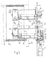
- Fig. 2 einen Schnitt in grösserem Massstab längs der Linie 11-11 ;
- Fig. 3 in nochmals etwas grösserem Massstab eine Ansicht in Richtung des Pfeiles 111 der Fig. 2, wobei gestrichelt die hinter der Seitenwand angeordneten Elemente angedeutet sind ;
- Fig. 4 in nochmals etwas grösserem Massstab eine Draufsicht, teilweise im Schnitt, aus Richtung des Pfeiles IV Fig. 2 auf das Führungsrad ; und
- Fig. 5 eine Ausführungsvariante in einer ähnlichen Darstellungsart wie Fig. 2, allerdings in nochmals grösserem Massstab.
- Es sei nun - auch im Sinne einer Erläuterung des Oberbegriffes des Patentanspruches 1 - zunächst auf Fig. 1 Bezug genommen.
- Bei der in Fig. 1 dargestellten Vorrichtung 10 treibt ein Motor 11 über eine Kette 12, ein Vorgelege 13, über ein Getriebe 14 sowie über eine weitere Kette 15 eine Umlenkrolle 16 eines Bändchenförderers 17 an. Der Bändchenförderer 17 ist von einem nicht dargestellten, wippenartigen Rahmen getragen, der um die Drehachse der Umlenkrolle 16 schwenkbar ist und mittels einer Gasfeder 18 stets an den Aussenumfang eines Wickelkernes 19, bezw. eines darauf in Bildung begriffenen Wickels 20 drängt. Der Bändchenförderer 17 führt dem Wickel die nicht dargestellten, biegsamen Flächengebilde zu, bezw. fördert soiche Flächengebilde beim Abwickeln des Wickels ab. Ueber eine weitere, vom Getriebe 14 ausgehende Kette 21 ist eine Vorratsrolle 22 für ein Wickelband 23 angetrieben, das seinerseits den Bändchenförderer 17 im Bereich dessen Berührungsstelle am Wickelkern 19, bzw. am Wickel 20 durchsetzt und im Zuge des Aufwickelns der vom Bändchenförderer angelieferten Flächengebilde (nicht dargestellt) mit aufgewickelt wird, bzw. beim Abwickeln des Wickels 20 wieder auf die Vorratsrolle 22 aufgespult wird.
- Vom Vorgelege 13 führt eine weitere Kette 24 zu einem Wickelgetriebe 25 mit selbsttätig stufenlos verändebaren Uebersetzungsverhältnis. Vom Wickelgetriebe 25 führt eine weitere Kette 26 zu zwei über nochmals eine Kette 27 zu gleichsinniger Drehung miteinander verbundenen Tragrädern 28, 29, auf denen der Wickelkern 19 gelagert ist und die - falls angetrieben - den Wickelkern 19 reibschlüssig in demselben Drehsinn antreiben. Ergänzt wird die Lagerung des Wickelkernes 19 durch ein im wesentlichen frei drehbares Führungsrad 30, das heb- und senkbar ist und In abgesenkter Stellung ebenfalls mit der Innenseite des Wickelkernes 19 zusammenwirkt und dann nicht nur ein ungewolltes Abheben des Wickelkernes 19 von einem der Tragräder 28, 29 verhindert, sondern auch zur Erhöhung des Reibschlusses zwischen diesen und der Innenseite 19a des Wickelkernes 19 beitragen kann. Durch die Räder 28, 29 und 30 ist damit auf alle Fälle eine zentrische Lage des Wickelkernes 19 gewährleistet.
- Es sei nun auf die Fig. 2-4 Bezug genommen. Man erkennt in Fig. 2 das Tragrad 28 sowie das Führungsrad 30, das mit ausgezogenen Linien in der Eingriffslage mit der glatten Innenseite 19a des Wickelkernes dargestellt ist. Ein Teil des Umrisses des Wickels 20 ist strichpunktiert dargestellt. Das Tragrad 28 ist auf einer Welle 31 aufgekeilt, die ihrerseits in zwei Wälzlagern 32, 33 drehbar in einem Lagergehäuse 34 gelagert ist. Das Lagergehäuse 34 ist fest an der einen Seite einer lotrechten Seitenwand 35 des Maschinenrahmens angeflanscht, wobei das vom Tragrad 28 entfernte Ende der Welle diese Wand 35 durchsetzt und die die Ketten 26 und 27 aufnehmenden Kettenräder 36, bzw. 37 aufgekeilt hat. Die Lagerung und Anordnung des Tragrades 29 entspricht jener des Tragrades 28.
- Das Führungsrad 30 ist ebenfalls auf einer Welle 38 aufgekeilt, die zunächst über ein Pendelwälzlager 39 in einem Lagergehäuse 40 drehbar gelagert ist. Das Lagergehäuse 40 ist auf einer ringförmigen Platte 41 angeflanscht, die ihrerseits (Vgl. Fig. 3 und 4) an einem Schlitten 42 verankert ist. Dieser in Fig. 3 durch eine dicke Umrandung hervorgehobene Schlitten 42 ist über Kugelbüchsen 43 (Fig. 2) verschiebbar auf zwei parallelen Säulen 44 und 45 geführt, sodass die Lenkachse des Lagergehäuses 40 damit bezüglich des Wickelkernes 19 radial verschiebbar ist, und zwar in einer In der Seitenwand 35 vorhandenen Aussparung 44'. Zum Heben und zum Senken des Lagergehäuses 40 dient ein Fluidikaggregat 45', dessen Kolbenstange 46 über ein Kreuzgelenk 47 (Fig. 2) in der Mitte des Schlittens 42 angelenkt ist.
- Aus Fig. 3 geht hervor, dass der Schlitten 42 im wesentlichen U-förmig ist. Er umgreift eine Lagerplatte 48, die ihrerseits durch an gegenüberliegenden Seiten nachgiebige Stifte 49, 50 (Fig. 4) so zwischen den Schenkeln des Schlittens 42 gehalten ist, dass sie sich in Bezug auf den Schlitten 42 nicht in einer zu den Säulen 44, 45 parallelen Richtung bewegen kann, sondern nur rechtwinklig dazu. Zu diesem Zweck ist an der Platte 48 bei 51 die Kolbenstange 52 eines weiteren Fluidikaggregates 53 angelenkt, dessen Zylinder bei 55 am Ende eines vom Schlitten 42 seitlich abstehenden Auslegers 54 angelenkt ist. Um die Lagerplatte 48 auch gegen ein Verkippen zu sichern, ist an ihrer dem Anlenkpunkt 51 gegenüberliegenden Seite ein Stift 56 verankert, der in ein am Schlitten 42 befestigtes Führungsstück 57 eingreift.
- In der Lagerplatte 48 ist ein weiteres Pendelwälzlager 58 montiert, in dem das vom Führungsrad 30 entfernte Ende der Welle 38 gelagert ist. Da sich die Lagerplatte 48 und damit auch das Pendelwälzlager 58 quer zur Richtung der Säulen 44, 45 verschieben lässt, kann die Welle 38 in einem beschränkten Winkelbereich um die Mitte des Pendenwälzlagers 39 verschwenkt werden, oder, mit anderen Worten entspricht diese Mitte einer Lenkachse 59, um die das Führungsrad 30 auslenkbar ist. In Fig. 4 ist ausgezogen der Umriss des unausgelenkten Führungsrades 30 dargestellt, strichpunktiert dagegen der Umriss in den beiden möglichen Endlagen der Auslenkung.
- Es sei nun angenommen, dass der Wickelkern 19 so auf die Tragräder 28, 29 aufgesetzt werde, dass die Stirnseiten des Wickelkernes 19 die in Fig. 4 mit 19' strichpunktiert angegebene Lage einnehmen. Der Wickelkern 19 sei sodann durch die Tragräder 28, 29 so in Drehung versetzt, dass die Innenseite des Wickelkernes, auf die das Führungsrad 30 einwirkt, sich in Richtung des Pfeiles 60 bewege. In axialer Richtung ist der Wickelkern 19 nun noch nicht genau positioniert. Es genügt nun, die Lagerplatte 48 in Fig. 4 nach oben zu verschieben, so dass die strichpunktiert angegebene Drehachse des Führungsrades 30 um wenige Grade im Gegenuhrzeigersinn um die Lenkachse 59 verschwenkt wird, wobei das Führungsrad 30 einen entsprechenden Lenkausschlag erhält. Durch diesen Lenkausschlag erteilt nun das Führungsrad 30 dem Wickelkern 19 eine Bewegungskomponente in Richtung des Pfeiles 61 in Fig. 4. Der Wickelkern 19 wandert somit während der Drehung in Richtung auf die Seitenwand 35 zu, das heisst auf seine richtige Axiallage.
- Die richtige Axiallage wird nun durch eine kreisbogenförmige Anschlagschiene 62 bestimmt, die (Siehe Fig. 2) am Lagergehäuse 40 der Welle 38 befestigt und daher mit diesem heb- und senkbar ist, wobei die Anschlagschiene konzentrisch zum aufgelegten Wickelkern ist. Um die Vorrichtung auch für Wickelkerne verschiedener axialer Längen benützen zu können, kann die Anschlagschiene 62 auch längs des Lagergehäuses 40 verschiebbar und feststellbar angeordnet werden. Andererseits können anstelle der Anschlagschiene 62 auch frei drehbare Anschlagrollen vorgesehen sein, deren Drehachsen radial zum aufgelegten Wickelkern gerichtet sind.
- Würde die Lagerplatte 48 in Fig. 4 nach unten verschoben, das heisst die Drehachse des Führungsrades 30 im Uhrzeigersinn um die Lenkachse 59 verschwenkt, ergäbe sich bei gleichbleibender Bewegungsrichtung (Pfeil 60) des Wickelkernes 19 eine den Pfeil 61 entgegengesetzte Bewegungskomponente. die ihrerseits die Entfernung des Wickelkernes 19 erleichtert.
- Wenn der Wickelkern 19 seine richtige Axiallage erreicht hat, kann der Lenkausschlag des Führungsrades 30 aufgehoben werden, sodass die Drehachse des Führungsrades wieder exakt parallel zu jenen der Tragräder 28, 29 ist. Damit unterbleibt die Bewegungskomponente des Pfeiles 61 und auch ein allfälliger Reibungsverlust an der Anschlagschiene 62.
- Während bei der anhand der Fig. 2-4 gezeigten Ausführungsform das Führungsrad 30 mit seiner Welle 38 stets frei drehbar ist und der Lenkausschlag des Führungsrades 30 durch Beaufschlagung des Aggregates 43 erzielt wird, kann der Umstand, dass die Lenkachse 59 ausserhalb der Mittenebene des Führungsrades 30 liegt, dazu ausgenützt werden, dessen Lenkausschlag auch auf andere Weise zu bewirken. Eine solche Ausführungsform ist in Fig. 5 skizziert.
- Das die Seitenwand 35 durchsetzende Ende der Welle 38 ist hier über ein Wälzlager 63 in einer ähnlich wie die Lagerplatte in bezug auf den Schlitten 42 quer zu den Säulen 44, 45 verschiebbaren Lagerhülse 64 gelagert. Die Welle 38 ist über das Wälzlager 63 verlängert und trägt über ein Kugellager 65 den einen Teil 66 einer elektromagnetischen Bremse 67, welcher Teil durch einen den Schlitten 42 übergreifenden Führungsbügel 68 gegen Verdrehung gesichert ist, ohne an einer Querverschiebung gehindert zu sein. Auf dem freien Ende der Welle 38 (rechts in Fig. 5) ist der andere Teil 69 der Bremse 67 aufgekeilt.
- Solange die Bremse 67 gelüftet ist, bleibt die Welle 38 durch die Wirkung der Stifte 49, 50 achsparallel zu den Drehachsen der Tragräder 28, 29, und dem Wickelkern 19 wird keine axiale Bewegungskomponente vermittelt. Wird aber die Bremse 67 betätigt, bewirkt die Bremsung des Führungsrades 30, dass dieses der Bewegungsrichtung 60 drehenden Wickelkernes 19 folgt und somit den Lenkausschlag um die Lenkachse 59 bewirkt. Dabei ist allerdings zu beachten, dass die Bremskraft so zu bemessen ist, dass das Führungsrad 30 nicht an einer Drehung verhindert, sondern nur gehemmt wird. Sobald die Bremse wieder gelüftet wird, stellt sich das Führungsrad 30 wieder achsparallel zu den Tragrädern 28, 29.
Claims (13)
Priority Applications (1)
| Application Number | Priority Date | Filing Date | Title |
|---|---|---|---|
| AT87104217T ATE39342T1 (de) | 1986-04-14 | 1987-03-21 | Vorrichtung zum auf- oder abwickeln von kontinuierlich anfallenden, biegsamen flaechengebilden. |
Applications Claiming Priority (2)
| Application Number | Priority Date | Filing Date | Title |
|---|---|---|---|
| CH1475/86 | 1986-04-14 | ||
| CH147586 | 1986-04-14 |
Publications (2)
| Publication Number | Publication Date |
|---|---|
| EP0242608A1 EP0242608A1 (de) | 1987-10-28 |
| EP0242608B1 true EP0242608B1 (de) | 1988-12-21 |
Family
ID=4211353
Family Applications (1)
| Application Number | Title | Priority Date | Filing Date |
|---|---|---|---|
| EP87104217A Expired EP0242608B1 (de) | 1986-04-14 | 1987-03-21 | Vorrichtung zum Auf- oder Abwickeln von kontinuierlich anfallenden, biegsamen Flächengebilden |
Country Status (7)
| Country | Link |
|---|---|
| US (1) | US4705227A (de) |
| EP (1) | EP0242608B1 (de) |
| JP (1) | JP2525596B2 (de) |
| AT (1) | ATE39342T1 (de) |
| CA (1) | CA1290305C (de) |
| DE (1) | DE3760025D1 (de) |
| SU (1) | SU1524804A3 (de) |
Families Citing this family (9)
| Publication number | Priority date | Publication date | Assignee | Title |
|---|---|---|---|---|
| CH679993A5 (de) * | 1987-03-06 | 1992-05-29 | Ferag Ag | |
| EP0477498B1 (de) * | 1990-09-28 | 1994-06-01 | Ferag AG | Einrichtung zum Aufwickeln von Druckereiprodukten |
| US5706692A (en) * | 1996-03-06 | 1998-01-13 | Tapco International Corporation | Combined portable sheet bending brake, coil holder and cut-off mechanism |
| CA2346287A1 (en) | 1998-10-05 | 2000-04-13 | Ferag Ag | Winding device for flexible, flat material, especially printed products |
| JP2001058761A (ja) * | 1999-06-08 | 2001-03-06 | Bridgestone Corp | 長尺塑性変形部材の保管方法および長尺塑性変形部材の保管装置 |
| US6431492B1 (en) * | 1999-10-27 | 2002-08-13 | Zih Corp. | Integrated adjustable core support and medium guide device |
| ES2277618T3 (es) * | 2001-07-11 | 2007-07-16 | Bridgestone Corporation | Procedimiento y dispositivo para almacenar elementos largos deformados plasticamente. |
| JP5605759B2 (ja) * | 2010-03-17 | 2014-10-15 | 株式会社リコー | ロール紙駆動装置、及び画像形成装置 |
| US10421571B2 (en) * | 2016-03-28 | 2019-09-24 | An-Sung Wang | System for sensing element adjustment and material belt detection |
Family Cites Families (5)
| Publication number | Priority date | Publication date | Assignee | Title |
|---|---|---|---|---|
| US3066388A (en) * | 1957-07-29 | 1962-12-04 | Moloney Electric Company | Methods for making magnetic cores |
| EP0139999B1 (de) * | 1983-09-19 | 1989-04-19 | Ferag AG | Wickelkern für einen aus biegsamen, flächigen Erzeugnissen, insbesondere Druckprodukten, gebildeten Wickel |
| EP0161569B1 (de) * | 1984-05-09 | 1989-10-18 | Ferag AG | Vorrichtung zum Aufwickeln bzw.Abwickeln von kontinuierlich, vorzugsweise in Schuppenformation, anfallenden Druckprodukten |
| US4657196A (en) * | 1984-09-04 | 1987-04-14 | Aluminum Company Of America | Mechanism for supporting and rotating a coil |
| US4659030A (en) * | 1985-10-11 | 1987-04-21 | Harris Graphics Corporation | Lateral positioning and adjustment mechanism for a web press |
-
1987
- 1987-03-21 EP EP87104217A patent/EP0242608B1/de not_active Expired
- 1987-03-21 DE DE8787104217T patent/DE3760025D1/de not_active Expired
- 1987-03-21 AT AT87104217T patent/ATE39342T1/de not_active IP Right Cessation
- 1987-04-02 JP JP62082186A patent/JP2525596B2/ja not_active Expired - Lifetime
- 1987-04-06 US US07/034,622 patent/US4705227A/en not_active Expired - Fee Related
- 1987-04-09 SU SU874202350A patent/SU1524804A3/ru active
- 1987-04-09 CA CA000534238A patent/CA1290305C/en not_active Expired - Fee Related
Also Published As
| Publication number | Publication date |
|---|---|
| DE3760025D1 (en) | 1989-01-26 |
| CA1290305C (en) | 1991-10-08 |
| JP2525596B2 (ja) | 1996-08-21 |
| EP0242608A1 (de) | 1987-10-28 |
| JPS62244848A (ja) | 1987-10-26 |
| ATE39342T1 (de) | 1989-01-15 |
| US4705227A (en) | 1987-11-10 |
| SU1524804A3 (ru) | 1989-11-23 |
Similar Documents
| Publication | Publication Date | Title |
|---|---|---|
| DE69801739T2 (de) | Umwickelvorrichtung | |
| EP0242608B1 (de) | Vorrichtung zum Auf- oder Abwickeln von kontinuierlich anfallenden, biegsamen Flächengebilden | |
| DE2739066A1 (de) | Vorrichtung zum zusammenbringen einer mehrzahl von feinen faeden o.dgl. | |
| EP0096774B1 (de) | Treiber zum selbstzentrierenden Antreiben von langgestrecktem Halbzeug | |
| DE2242993C3 (de) | Transportriementrieb | |
| DE1499046B2 (de) | Verfahrbare vorrichtung zum auf und abrollen von bedeckungs elementen wie planen vorhaenge geflaechte oder strohmatten | |
| EP0232553B1 (de) | Einrichtung zum Aufwickeln eines kontinuierlich anfallenden Schuppenstromes von biegsamen Flächengebilden zu einem Wickel | |
| DE4000469C2 (de) | Hülsenspannvorrichtung zum Aufwickeln von schmalen Bahnen oder Streifen aus Papier, Folie oder dgl., insbesondere Bändchen aus Dünnstfolie | |
| DE2328993B1 (de) | Aufspuleinrichtung | |
| DE3426063C2 (de) | ||
| DE1274413B (de) | Vorrichtung zum Anhalten einzelner Abschnitte einer kontinuierlich laufenden Materialbahn | |
| DE2558162C2 (de) | Vorrichtung zum seitlichen Strecken einer Bahn aus Textilmaterial oder dergleichen | |
| EP0933320B1 (de) | Rollenwickler | |
| EP0629574A1 (de) | Ladevorrichtung für Material, insbesondere für Papier-Rollen | |
| DE2449923A1 (de) | Rotationsoffsetmaschine | |
| DE2535759A1 (de) | Wagen fuer den transport von kabeltrommeln, insbesondere waehrend des verlegens der kabel | |
| DE2502213A1 (de) | Vorrichtung zum mechanischen ziehen von kabeln | |
| DE916707C (de) | Vorrichtung zum selbsttaetigen Geradefuehren von Gewebebahnen | |
| EP1119510A1 (de) | Wickelvorrichtung für flexible flächengebilde, insbesondere druckereiprodukte | |
| EP0326687B1 (de) | Drehbare Lagerung eines Wickelkerns und Wickelkern | |
| DE2237014C3 (de) | Spannmaschine für Warenbahnen | |
| DE2951336A1 (de) | Vorrichtung zum abrollen von materialbahnen von wechselnden vorratsrollen | |
| DE2129410B2 (de) | Vorrichtung zum kontinuierlichen aufwickeln | |
| DE2427250A1 (de) | Vorrichtung zum auf- und abwickeln bahnenfoermiger ware, z.b. fussbodenbelaege | |
| DE3139493C2 (de) | Vorrichtung zum Halten eines maschinell zu bewickelnden Ringkernes |
Legal Events
| Date | Code | Title | Description |
|---|---|---|---|
| PUAI | Public reference made under article 153(3) epc to a published international application that has entered the european phase |
Free format text: ORIGINAL CODE: 0009012 |
|
| AK | Designated contracting states |
Kind code of ref document: A1 Designated state(s): AT CH DE FR GB IT LI SE |
|
| 17P | Request for examination filed |
Effective date: 19870919 |
|
| 17Q | First examination report despatched |
Effective date: 19880525 |
|
| ITF | It: translation for a ep patent filed | ||
| GRAA | (expected) grant |
Free format text: ORIGINAL CODE: 0009210 |
|
| AK | Designated contracting states |
Kind code of ref document: B1 Designated state(s): AT CH DE FR GB IT LI SE |
|
| REF | Corresponds to: |
Ref document number: 39342 Country of ref document: AT Date of ref document: 19890115 Kind code of ref document: T |
|
| REF | Corresponds to: |
Ref document number: 3760025 Country of ref document: DE Date of ref document: 19890126 |
|
| ET | Fr: translation filed | ||
| GBT | Gb: translation of ep patent filed (gb section 77(6)(a)/1977) | ||
| PLBE | No opposition filed within time limit |
Free format text: ORIGINAL CODE: 0009261 |
|
| STAA | Information on the status of an ep patent application or granted ep patent |
Free format text: STATUS: NO OPPOSITION FILED WITHIN TIME LIMIT |
|
| 26N | No opposition filed | ||
| ITTA | It: last paid annual fee | ||
| PGFP | Annual fee paid to national office [announced via postgrant information from national office to epo] |
Ref country code: FR Payment date: 19930219 Year of fee payment: 7 |
|
| PGFP | Annual fee paid to national office [announced via postgrant information from national office to epo] |
Ref country code: AT Payment date: 19930223 Year of fee payment: 7 |
|
| PGFP | Annual fee paid to national office [announced via postgrant information from national office to epo] |
Ref country code: GB Payment date: 19940215 Year of fee payment: 8 |
|
| PGFP | Annual fee paid to national office [announced via postgrant information from national office to epo] |
Ref country code: SE Payment date: 19940223 Year of fee payment: 8 |
|
| PG25 | Lapsed in a contracting state [announced via postgrant information from national office to epo] |
Ref country code: AT Effective date: 19940321 |
|
| PG25 | Lapsed in a contracting state [announced via postgrant information from national office to epo] |
Ref country code: FR Effective date: 19941130 |
|
| REG | Reference to a national code |
Ref country code: FR Ref legal event code: ST |
|
| EAL | Se: european patent in force in sweden |
Ref document number: 87104217.2 |
|
| PGFP | Annual fee paid to national office [announced via postgrant information from national office to epo] |
Ref country code: DE Payment date: 19950211 Year of fee payment: 9 |
|
| PG25 | Lapsed in a contracting state [announced via postgrant information from national office to epo] |
Ref country code: GB Effective date: 19950321 |
|
| PG25 | Lapsed in a contracting state [announced via postgrant information from national office to epo] |
Ref country code: SE Effective date: 19950322 |
|
| GBPC | Gb: european patent ceased through non-payment of renewal fee |
Effective date: 19950321 |
|
| EUG | Se: european patent has lapsed |
Ref document number: 87104217.2 |
|
| PG25 | Lapsed in a contracting state [announced via postgrant information from national office to epo] |
Ref country code: DE Effective date: 19961203 |
|
| PGFP | Annual fee paid to national office [announced via postgrant information from national office to epo] |
Ref country code: CH Payment date: 19990329 Year of fee payment: 13 |
|
| PG25 | Lapsed in a contracting state [announced via postgrant information from national office to epo] |
Ref country code: LI Free format text: LAPSE BECAUSE OF NON-PAYMENT OF DUE FEES Effective date: 20000331 Ref country code: CH Free format text: LAPSE BECAUSE OF NON-PAYMENT OF DUE FEES Effective date: 20000331 |
|
| REG | Reference to a national code |
Ref country code: CH Ref legal event code: PL |
|
| PG25 | Lapsed in a contracting state [announced via postgrant information from national office to epo] |
Ref country code: IT Free format text: LAPSE BECAUSE OF NON-PAYMENT OF DUE FEES;WARNING: LAPSES OF ITALIAN PATENTS WITH EFFECTIVE DATE BEFORE 2007 MAY HAVE OCCURRED AT ANY TIME BEFORE 2007. THE CORRECT EFFECTIVE DATE MAY BE DIFFERENT FROM THE ONE RECORDED. Effective date: 20050321 |