EP0240198A2 - Extruder für Gummimaterial - Google Patents
Extruder für Gummimaterial Download PDFInfo
- Publication number
- EP0240198A2 EP0240198A2 EP87302227A EP87302227A EP0240198A2 EP 0240198 A2 EP0240198 A2 EP 0240198A2 EP 87302227 A EP87302227 A EP 87302227A EP 87302227 A EP87302227 A EP 87302227A EP 0240198 A2 EP0240198 A2 EP 0240198A2
- Authority
- EP
- European Patent Office
- Prior art keywords
- casing
- bore
- sleeve
- screw
- projections
- Prior art date
- Legal status (The legal status is an assumption and is not a legal conclusion. Google has not performed a legal analysis and makes no representation as to the accuracy of the status listed.)
- Granted
Links
Images
Classifications
-
- B—PERFORMING OPERATIONS; TRANSPORTING
- B29—WORKING OF PLASTICS; WORKING OF SUBSTANCES IN A PLASTIC STATE IN GENERAL
- B29C—SHAPING OR JOINING OF PLASTICS; SHAPING OF MATERIAL IN A PLASTIC STATE, NOT OTHERWISE PROVIDED FOR; AFTER-TREATMENT OF THE SHAPED PRODUCTS, e.g. REPAIRING
- B29C48/00—Extrusion moulding, i.e. expressing the moulding material through a die or nozzle which imparts the desired form; Apparatus therefor
- B29C48/25—Component parts, details or accessories; Auxiliary operations
- B29C48/78—Thermal treatment of the extrusion moulding material or of preformed parts or layers, e.g. by heating or cooling
- B29C48/80—Thermal treatment of the extrusion moulding material or of preformed parts or layers, e.g. by heating or cooling at the plasticising zone, e.g. by heating cylinders
- B29C48/83—Heating or cooling the cylinders
- B29C48/834—Cooling
-
- B—PERFORMING OPERATIONS; TRANSPORTING
- B29—WORKING OF PLASTICS; WORKING OF SUBSTANCES IN A PLASTIC STATE IN GENERAL
- B29C—SHAPING OR JOINING OF PLASTICS; SHAPING OF MATERIAL IN A PLASTIC STATE, NOT OTHERWISE PROVIDED FOR; AFTER-TREATMENT OF THE SHAPED PRODUCTS, e.g. REPAIRING
- B29C48/00—Extrusion moulding, i.e. expressing the moulding material through a die or nozzle which imparts the desired form; Apparatus therefor
- B29C48/25—Component parts, details or accessories; Auxiliary operations
- B29C48/256—Exchangeable extruder parts
- B29C48/2562—Mounting or handling of the die
-
- B—PERFORMING OPERATIONS; TRANSPORTING
- B29—WORKING OF PLASTICS; WORKING OF SUBSTANCES IN A PLASTIC STATE IN GENERAL
- B29C—SHAPING OR JOINING OF PLASTICS; SHAPING OF MATERIAL IN A PLASTIC STATE, NOT OTHERWISE PROVIDED FOR; AFTER-TREATMENT OF THE SHAPED PRODUCTS, e.g. REPAIRING
- B29C48/00—Extrusion moulding, i.e. expressing the moulding material through a die or nozzle which imparts the desired form; Apparatus therefor
- B29C48/25—Component parts, details or accessories; Auxiliary operations
- B29C48/36—Means for plasticising or homogenising the moulding material or forcing it through the nozzle or die
- B29C48/395—Means for plasticising or homogenising the moulding material or forcing it through the nozzle or die using screws surrounded by a cooperating barrel, e.g. single screw extruders
- B29C48/397—Means for plasticising or homogenising the moulding material or forcing it through the nozzle or die using screws surrounded by a cooperating barrel, e.g. single screw extruders using a single screw
-
- B—PERFORMING OPERATIONS; TRANSPORTING
- B29—WORKING OF PLASTICS; WORKING OF SUBSTANCES IN A PLASTIC STATE IN GENERAL
- B29C—SHAPING OR JOINING OF PLASTICS; SHAPING OF MATERIAL IN A PLASTIC STATE, NOT OTHERWISE PROVIDED FOR; AFTER-TREATMENT OF THE SHAPED PRODUCTS, e.g. REPAIRING
- B29C48/00—Extrusion moulding, i.e. expressing the moulding material through a die or nozzle which imparts the desired form; Apparatus therefor
- B29C48/25—Component parts, details or accessories; Auxiliary operations
- B29C48/36—Means for plasticising or homogenising the moulding material or forcing it through the nozzle or die
- B29C48/50—Details of extruders
- B29C48/505—Screws
- B29C48/64—Screws with two or more threads
- B29C48/645—Screws with two or more threads neighbouring threads and channels having identical configurations
-
- B—PERFORMING OPERATIONS; TRANSPORTING
- B29—WORKING OF PLASTICS; WORKING OF SUBSTANCES IN A PLASTIC STATE IN GENERAL
- B29C—SHAPING OR JOINING OF PLASTICS; SHAPING OF MATERIAL IN A PLASTIC STATE, NOT OTHERWISE PROVIDED FOR; AFTER-TREATMENT OF THE SHAPED PRODUCTS, e.g. REPAIRING
- B29C48/00—Extrusion moulding, i.e. expressing the moulding material through a die or nozzle which imparts the desired form; Apparatus therefor
- B29C48/25—Component parts, details or accessories; Auxiliary operations
- B29C48/36—Means for plasticising or homogenising the moulding material or forcing it through the nozzle or die
- B29C48/50—Details of extruders
- B29C48/68—Barrels or cylinders
- B29C48/6801—Barrels or cylinders characterised by the material or their manufacturing process
-
- B—PERFORMING OPERATIONS; TRANSPORTING
- B29—WORKING OF PLASTICS; WORKING OF SUBSTANCES IN A PLASTIC STATE IN GENERAL
- B29C—SHAPING OR JOINING OF PLASTICS; SHAPING OF MATERIAL IN A PLASTIC STATE, NOT OTHERWISE PROVIDED FOR; AFTER-TREATMENT OF THE SHAPED PRODUCTS, e.g. REPAIRING
- B29C48/00—Extrusion moulding, i.e. expressing the moulding material through a die or nozzle which imparts the desired form; Apparatus therefor
- B29C48/25—Component parts, details or accessories; Auxiliary operations
- B29C48/36—Means for plasticising or homogenising the moulding material or forcing it through the nozzle or die
- B29C48/50—Details of extruders
- B29C48/68—Barrels or cylinders
- B29C48/685—Barrels or cylinders characterised by their inner surfaces, e.g. having grooves, projections or threads
- B29C48/687—Barrels or cylinders characterised by their inner surfaces, e.g. having grooves, projections or threads having projections with a short length in the barrel direction, e.g. pins
-
- B—PERFORMING OPERATIONS; TRANSPORTING
- B29—WORKING OF PLASTICS; WORKING OF SUBSTANCES IN A PLASTIC STATE IN GENERAL
- B29C—SHAPING OR JOINING OF PLASTICS; SHAPING OF MATERIAL IN A PLASTIC STATE, NOT OTHERWISE PROVIDED FOR; AFTER-TREATMENT OF THE SHAPED PRODUCTS, e.g. REPAIRING
- B29C48/00—Extrusion moulding, i.e. expressing the moulding material through a die or nozzle which imparts the desired form; Apparatus therefor
- B29C48/25—Component parts, details or accessories; Auxiliary operations
- B29C48/78—Thermal treatment of the extrusion moulding material or of preformed parts or layers, e.g. by heating or cooling
- B29C48/80—Thermal treatment of the extrusion moulding material or of preformed parts or layers, e.g. by heating or cooling at the plasticising zone, e.g. by heating cylinders
- B29C48/83—Heating or cooling the cylinders
- B29C48/832—Heating
-
- B—PERFORMING OPERATIONS; TRANSPORTING
- B29—WORKING OF PLASTICS; WORKING OF SUBSTANCES IN A PLASTIC STATE IN GENERAL
- B29C—SHAPING OR JOINING OF PLASTICS; SHAPING OF MATERIAL IN A PLASTIC STATE, NOT OTHERWISE PROVIDED FOR; AFTER-TREATMENT OF THE SHAPED PRODUCTS, e.g. REPAIRING
- B29C48/00—Extrusion moulding, i.e. expressing the moulding material through a die or nozzle which imparts the desired form; Apparatus therefor
- B29C48/03—Extrusion moulding, i.e. expressing the moulding material through a die or nozzle which imparts the desired form; Apparatus therefor characterised by the shape of the extruded material at extrusion
-
- B—PERFORMING OPERATIONS; TRANSPORTING
- B29—WORKING OF PLASTICS; WORKING OF SUBSTANCES IN A PLASTIC STATE IN GENERAL
- B29K—INDEXING SCHEME ASSOCIATED WITH SUBCLASSES B29B, B29C OR B29D, RELATING TO MOULDING MATERIALS OR TO MATERIALS FOR MOULDS, REINFORCEMENTS, FILLERS OR PREFORMED PARTS, e.g. INSERTS
- B29K2021/00—Use of unspecified rubbers as moulding material
Definitions
- the present invention relates to an extruder for mixing, homogenizing and extruding rubber materials, such as natural rubber and synthetic rubber.
- a conventional extruder of this type includes a casing forming a cylindrical bore that contains a rotatable screw which forms a spiral passage for rubber materials in the casing.
- a number of mixing pins radially extend through the casing, so that adjustable lengths of the pins project into the spiral passage. Some of the pins extend through a space in the casing formed for a heating or cooling medium.
- the thread of the screw is formed with notches for the pins to pass through when the screw rotates.
- An extruder includes a casing which forms a cylindrical bore and a peripheral passage for a heating or cooling medium around the bore.
- a screw is mounted in the bore and axially fixed to the casing, but adapted to be rotated in the bore.
- the screw has a thread forming a spiral passage for rubber materials in the bore.
- a number of projections extend from the casing and into the spiral passage. The thread is formed with notches for the projections to pass through as the screw rotates.
- a cylindrical sleeve is mounted within the casing and supports the projections. The casing and the sleeve are divided or split into at least two parts, and lock means is provided on the casing to lock the parts together during operation.
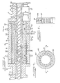
- an extruder includes an inlet section 11 into which rubber materials are fed, a main or center section 13 in which the materials are mixed together, and a head section 15 from which the mixture is extruded in a predetermined cross-sectional shape.
- the sections 11, 13 and 15 include tubular casings 17, 19 and 21, respectively, which are secured together in endto-end relationship.
- the three casings have aligned cylindrical bores 18, 20 and 22 formed through them, and a rotatable screw 23 extends through the bores.
- the screw 23 is journalled at both ends by bearings on the casings 17 and 21, and it is coupled at one end thereof to a drive (not shown).
- the inlet casing 17 has its bore 18 closed at its rear end by a closure 24, and an inlet port 25 is formed in one side.
- the port 25 is provided with a feeder 27 and a hopper (not shown) may be provided on the feeder.
- the head casing 21 has an open front end 28.
- the center casing 19 includes an outer axially extending wall 29 which is oval in radial cross section, and an inner cylindrical wall 31.
- the casing 19 is circumferentially divided into upper and lower halves.
- Each casing half is formed with a longitudinal passage 33 between the outer and inner walls 29 and 31 for the flow of a heating/cooling medium for maintaining the materials being processed at a desired temperature.
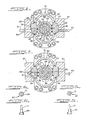
- Each casing half also has a pair of longitudinal flanges 35 projecting outwardly from the outer wall 29 on both side edges thereof.
- a pair of longitudinally extending clamps 37 are provided adjacent the flanges 35, each formed with a longitudinal groove 39 therein for engagement with the flanges 35 on one side of the casing 19 when closed.
- the clamps 37 engage tapered outer surfaces 36 of the flanges 35 and tightly secure the flanges (and the casings) together.
- the flanges as shown in Fig. 2, are fastened to the outer and inner walls.
- the inner casing walls 31 surround a tubular sleeve 41 which is circumferentially divided into two half circle parts, and the two parts are axially divided to form a plurality of axially aligned pairs of arcuate segments 43.
- the screw 23 has a pair of spiral ribs or double male threads 45, which form spiral passages 47 for the rubber materials inside the sleeve 41.
- the outer surfaces of the threads are closely adjacent the inner surface of the sleeve 41.
- the threads 45 have a pitch which reduces gradually from the rear end 24 of the inlet section 11 to the front end of the main section 13. The pitch reduction produces a gradual increase in pressure on the materials to heat and mix them.
- the threads 45 of a section of the screw within the center casting 13 are formed with axially spaced pairs of circumferentially aligned notches 49 therein.
- a plurality of bolts 51 extend loosely through the clamps 37 and are threaded into the lower casing flanges 35. Threaded on the bolts 51 are nuts 52 for engagement with the clamps 37 to clamp the halves of the casing 19 and the segments 43.
- Threaded holes are formed through the clamps 37 and a plurality of releasing bolts 53 are threaded into the holes and engage the lower flanges 35. By screwing the bolts 53 in, the clamps are pushed away and released.
- the bolts 51 and 53 are provided alternately along the length of the clamps 37, but only some of the bolts are shown in Fig. 1.
- the arcuate segments 43 of the sleeve 41 and the inner wall 31 of the upper casing half are formed with corresponding axial grooves 55 for engagement with an axially extending key 57 (Figs. 2 and 6a) to normally fix them together and prevent relative rotation.
- the grooves 55 are positioned so as to angularly displace the diametrical border edges 59 of the segments 43 away from the side flanges 37 of the casing, as shown in Fig. 2.
- a plurality of tightening bolts 61 are threaded through one of the lower flanges 35, and extend through the casing 19 in parallel with the bolts 51 and 53.
- Each bolt 61 is provided for engagement with one arcuate segment 43 of each pair at an angular location away from the border edges 59.
- the bolts 61 can be passed through holes 63 formed in the appropriate clamp 37, in order to more positively clamp the segments 43 in addition to the clamping by the clamps 37.
- each segment 43 is formed with a number of circumferentially aligned radial holes 65.
- Each hole 65 has an inner bore portion and a radially outer counterbore which is increased in diameter relative to the inner bore.
- the holes 65 are aligned with the notches 49 of the threads of the screw.
- Through each hole 65 extends a pin 67.
- each pin 67 has a double diameter head 69 for rotatable engagement within a hole 65, and a smaller diameter leg 71 which projects radially inwardly from the associated segment 43 into one spiral passage 47.
- the leg 71 is axially located to pass through the thread notches 49 when the screw 23 rotates. This construction enables a larger number of pins 67 to be provided for more uniform mixing of the materials. As shown in Figs. 4a and 5a, the legs 71 preferably have a tapered or streamlined shape.
- the screw 23 is rotated by a drive. Rubber materials are fed through the intake port 25 into the inlet section 11, and thrusted axially forwardly (toward the left) by the screw 23 to the main section 13. In addition, because the pitch of the threads 45 decreases in the forward direction, the materials are thrusted spirally forwardly along the passages 47 with increasing pressure, and consequently kneaded and mixed. The materials then move in contact with the stationary (and rotatable) pins 67, which promote the mixing.
- the pins 71 are preferably streamlined or tapered, and the pins are rotatable in their holes.
- the flow of the processed material causes the rotatable pins 67 to rotate to the positions where they have the minimum resistance to flow. This also reduces the loads on the pins.
- the mixed material is extruded from the open end 28 of the head section 15 in a predetermined cross-sectional shape which is determined by this shape of the opening 28 or a die (not shown).
- the pins 67 may have a shape and/or length depending upon and suited to a specific type of material.
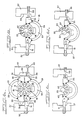
- the pins may be replaced depending on the nature of the material, or the sleeve 41 can be disassembled for inspection and repair, in the following manner:
- the releasing bolts 53 are threaded into the clamps 37 to push the clamps from the casing flanges 35.
- one or more pairs of arcuate segments 43 are rotated by a necessary angle to the position where the upper segment is accessible, and the upper segment is removed.
- New pins and segments can then be assembled in the reverse order.
- the second embodiment shown in Figs. 7-8 differs from the first embodiment in that the second includes arcuate segments 143 with a number of fins 167, instead of the pins.
- the fins 167 are formed integrally with and extend inwardly from the inner surfaces of the segments 143, inwardly toward the screw (not shown) and the fins are at an angle with respect to the axis of the segments 143 and the screw.
- the shape and direction of the fins 167 are predetermined depending on the pitch of the screw threads and the kind of the materials being processed.
- the sleeve 41 may otherwise include a number of undivided rings (not shown) without pins 67 or fins 167, which are interposed between other axially shortened arcuate segments (also not shown) which are provided with pins or fins. Also, the sleeve 41 may be circumferentially divided into three or more arcuate segments instead of two as illustrated.
Landscapes
- Engineering & Computer Science (AREA)
- Mechanical Engineering (AREA)
- Physics & Mathematics (AREA)
- Thermal Sciences (AREA)
- Manufacturing & Machinery (AREA)
- Extrusion Moulding Of Plastics Or The Like (AREA)
Applications Claiming Priority (2)
| Application Number | Priority Date | Filing Date | Title |
|---|---|---|---|
| JP61076347A JPS62231719A (ja) | 1986-04-01 | 1986-04-01 | ゴム材料の押出装置 |
| JP76347/86 | 1986-04-01 |
Publications (3)
| Publication Number | Publication Date |
|---|---|
| EP0240198A2 true EP0240198A2 (de) | 1987-10-07 |
| EP0240198A3 EP0240198A3 (en) | 1989-04-12 |
| EP0240198B1 EP0240198B1 (de) | 1992-08-12 |
Family
ID=13602820
Family Applications (1)
| Application Number | Title | Priority Date | Filing Date |
|---|---|---|---|
| EP19870302227 Expired - Lifetime EP0240198B1 (de) | 1986-04-01 | 1987-03-16 | Extruder für Gummimaterial |
Country Status (6)
| Country | Link |
|---|---|
| US (1) | US4723901A (de) |
| EP (1) | EP0240198B1 (de) |
| JP (1) | JPS62231719A (de) |
| KR (1) | KR930004047B1 (de) |
| CN (1) | CN1009908B (de) |
| DE (1) | DE3780996T2 (de) |
Cited By (1)
| Publication number | Priority date | Publication date | Assignee | Title |
|---|---|---|---|---|
| WO2008043329A3 (de) * | 2006-10-11 | 2010-12-09 | Harburg-Freudenberger Maschinenbau Gmbh | Vorrichtung zum extrudieren sowie das verfahren zur herstellung der temperierräume eines extruders und verfahren zur durchführung eines laserauftragsschweissens |
Families Citing this family (29)
| Publication number | Priority date | Publication date | Assignee | Title |
|---|---|---|---|---|
| EP0303728B1 (de) * | 1987-08-21 | 1991-09-11 | Schumacher, Walter Dr. Ing. | Vorrichtung zum Extrudieren, Expandieren und/oder thermischen Behandeln von Stoffen und Stoffgemischen |
| CH674960A5 (de) * | 1988-06-10 | 1990-08-15 | Rcm Rubber Consulting Mach | |
| DE4010540C1 (de) * | 1990-04-02 | 1991-11-07 | Wilfried Dipl.-Ing. 3017 Pattensen De Baumgarten | |
| DE4012612A1 (de) * | 1990-04-20 | 1991-10-24 | Wilfried Baumgarten | Schneckenextruder |
| DE4039942C1 (de) * | 1990-12-14 | 1992-01-30 | Berstorff Gmbh Masch Hermann | |
| US5304054A (en) * | 1991-04-19 | 1994-04-19 | Frenkel C-D Aktiengesellschaft | Plasticizing sections of cold feed rubber extruders |
| DE4141328C1 (de) * | 1991-12-14 | 1993-02-04 | Buss Ag, Basel, Ch | |
| US5219589A (en) * | 1992-01-22 | 1993-06-15 | Bridgestone/Firestone, Inc. | Vented kneading pin for extruder |
| DE4244312C1 (de) * | 1992-12-28 | 1994-01-20 | Baumgarten Wilfried | Schneckenextruder |
| US5749649A (en) * | 1996-03-05 | 1998-05-12 | Dynamic Mixers Inc. | Satellite extruder arrangement for polymer melt mixing with a dynamic mixer |
| CN1176877A (zh) | 1997-09-03 | 1998-03-25 | 青岛化工学院 | 挤出机螺旋啮合喂料方法 |
| US6241375B1 (en) * | 1998-08-01 | 2001-06-05 | Peter Wang | Shear ring screw |
| US6250791B1 (en) * | 2000-06-16 | 2001-06-26 | Loren T. Schneider | Liner and pin assembly for use with an apparatus for kneading or mixing materials |
| JP2002122244A (ja) * | 2000-10-16 | 2002-04-26 | Daicel Chem Ind Ltd | 軸封装置 |
| KR100415769B1 (ko) * | 2002-02-22 | 2004-01-24 | 주식회사 동방이엔지 | 쓰레기고형연료 압출기 |
| US20070062886A1 (en) * | 2005-09-20 | 2007-03-22 | Rego Eric J | Reduced pressure drop coalescer |
| FR2961116B1 (fr) * | 2010-06-14 | 2012-08-03 | Michelin Soc Tech | Installation et procede de synchronisation d'un melangeur interne |
| CN102173044B (zh) * | 2011-02-24 | 2013-07-24 | 华南理工大学 | 一种叶片挤出机及其叶片的载荷平衡及自润滑方法 |
| US10426129B2 (en) | 2013-11-27 | 2019-10-01 | Tetra Laval Holdings & Finance S.A. | Cheese-making methods and apparatuses |
| DE202014002902U1 (de) | 2014-04-04 | 2014-04-29 | Blach Verwaltungs Gmbh & Co. Kg | Mehrwellenextruder mit einem Extrudergehäuse |
| DE102014004865B4 (de) | 2014-04-04 | 2016-12-01 | Blach Verwaltungs Gmbh & Co. Kg | Mehrwellenextruder mit einem Extrudergehäuse und Einsatz zur Anordnung |
| CA2946564C (en) | 2014-04-21 | 2022-06-21 | Johnson Industries International, Inc. | Continuous cooker stretcher and methods of use thereof |
| CN103921426B (zh) * | 2014-05-05 | 2016-06-01 | 北京化工大学 | 一种聚合物熔体微积分强化传热与混炼塑化挤出机 |
| US10278360B2 (en) * | 2015-02-20 | 2019-05-07 | Tetra Laval Holdings & Finance S.A. | Single auger extruder |
| KR102436078B1 (ko) * | 2016-12-21 | 2022-08-25 | 바스프 에스이 | 단일-샤프트 압출기 및 단일-샤프트 압출기를 사용해 초흡수성 폴리머 겔 (sap 겔) 의 모폴러지를 변경하기 위한 방법 |
| US11235526B2 (en) * | 2018-11-07 | 2022-02-01 | Seiko Epson Corporation | Plasticizing device, three-dimensional modeling device, and injection molding device |
| CN110696268A (zh) * | 2019-08-29 | 2020-01-17 | 中宇环行(大连)发展有限公司 | 一种智能挤注成型联体机 |
| DE102020214857A1 (de) | 2020-11-26 | 2022-06-02 | Continental Reifen Deutschland Gmbh | Vorrichtung zum Extrudieren einer Kautschukmischung mit einer Mooney-Viskosität von über 50 MU und Verwendung der Vorrichtung zum Extrudieren einer ersten zu einer zweiten Kautschukmischung sowie zum Extrudieren einer dritten zu einer vierten Kautschukmischung |
| DE102023133845A1 (de) * | 2023-12-04 | 2025-06-05 | Extruder Experts Gmbh & Co. Kg | Gehäusesegment und Verfahren zum Herstellen desselben |
Family Cites Families (13)
| Publication number | Priority date | Publication date | Assignee | Title |
|---|---|---|---|---|
| US1904884A (en) * | 1933-04-18 | royle | ||
| GB614441A (en) * | 1946-04-15 | 1948-12-15 | Paul O Abbe Inc | Improvements in methods and apparatus for mixing, rendering plastic and reducing pulverulent materials |
| NL187631B (nl) * | 1954-05-17 | 1900-01-01 | Kali Chemie Ag | Werkwijze voor het bereiden van geneesmiddelen die angst en spanning wegnemen of verminderen, alsmede werkwijze voor het bereiden van geneeskrachtige verbindingen die geschikt zijn om daarbij te worden gebruikt. |
| US3023455A (en) * | 1959-03-09 | 1962-03-06 | Herbert F Geier | Mixers |
| US3458894A (en) * | 1966-09-13 | 1969-08-05 | Baker Perkins Inc | Mixing apparatus |
| US4178104A (en) * | 1972-07-21 | 1979-12-11 | Uniroyal, Ag | Method and apparatus for mixing viscous materials |
| DE2243039C3 (de) * | 1972-09-01 | 1980-08-14 | Werner & Pfleiderer, 7000 Stuttgart | Kontinuierlich arbeitender Schnekkenknetmischer |
| DE2423785C2 (de) * | 1974-05-16 | 1980-06-12 | Werner & Pfleiderer, 7000 Stuttgart | Verschleißeinsatz für das Schneckengehäuse einer Doppelschneckenstrangpresse oder -Spritzgießmaschine |
| US4385876A (en) * | 1978-05-31 | 1983-05-31 | Baker Perkins Inc. | Split wear liner for twin bore barrel assembly |
| GB2150037B (en) * | 1983-11-26 | 1986-11-12 | Farrel Bridge Ltd | Extruder barrel construction |
| DE3438649A1 (de) * | 1984-10-22 | 1986-04-24 | Windmöller & Hölscher, 4540 Lengerich | Einschneckenstrangpresse fuer thermoplastische und elastomere massen |
| ES8607810A1 (es) * | 1985-04-30 | 1986-06-01 | Gumix Sa | Una maquina extrusora-turbomezcladora |
| ES8607809A1 (es) * | 1985-04-30 | 1986-06-01 | Gumix Sa | Maquina extrusora-turbomezcladora |
-
1986
- 1986-04-01 JP JP61076347A patent/JPS62231719A/ja active Granted
-
1987
- 1987-03-16 DE DE8787302227T patent/DE3780996T2/de not_active Expired - Fee Related
- 1987-03-16 EP EP19870302227 patent/EP0240198B1/de not_active Expired - Lifetime
- 1987-03-24 US US07/030,045 patent/US4723901A/en not_active Expired - Fee Related
- 1987-03-30 CN CN87102395A patent/CN1009908B/zh not_active Expired
- 1987-04-01 KR KR1019870003091A patent/KR930004047B1/ko not_active Expired - Fee Related
Cited By (1)
| Publication number | Priority date | Publication date | Assignee | Title |
|---|---|---|---|---|
| WO2008043329A3 (de) * | 2006-10-11 | 2010-12-09 | Harburg-Freudenberger Maschinenbau Gmbh | Vorrichtung zum extrudieren sowie das verfahren zur herstellung der temperierräume eines extruders und verfahren zur durchführung eines laserauftragsschweissens |
Also Published As
| Publication number | Publication date |
|---|---|
| KR930004047B1 (ko) | 1993-05-19 |
| JPH0344891B2 (de) | 1991-07-09 |
| JPS62231719A (ja) | 1987-10-12 |
| CN87102395A (zh) | 1987-10-14 |
| US4723901A (en) | 1988-02-09 |
| CN1009908B (zh) | 1990-10-10 |
| KR870009836A (ko) | 1987-11-30 |
| EP0240198A3 (en) | 1989-04-12 |
| EP0240198B1 (de) | 1992-08-12 |
| DE3780996T2 (de) | 1993-03-25 |
| DE3780996D1 (de) | 1992-09-17 |
Similar Documents
| Publication | Publication Date | Title |
|---|---|---|
| US4723901A (en) | Extruder for rubber materials | |
| EP0509779B1 (de) | Verbesserungen bei Kautschuk-Extrudern mit Kaltbeschickung | |
| TWI633002B (zh) | 擠壓機用螺桿與擠壓機及擠壓方法 | |
| JP2966735B2 (ja) | 熱可塑性樹脂押出機 | |
| JP2834405B2 (ja) | 連続混練機 | |
| US4199263A (en) | Method and apparatus for mixing viscous materials | |
| EP0110694B1 (de) | Schneckenextruder | |
| US4447156A (en) | Modular mixing apparatus including interchangeable fluid processing means | |
| KR101999038B1 (ko) | 압출기용 스크루, 스크루 엘리먼트, 압출기 및 압출 방법 | |
| JPS5818138B2 (ja) | 連続混合機 | |
| WO2015156230A1 (ja) | 押出機用スクリュ、押出機および押出方法 | |
| US7270471B2 (en) | Extruder | |
| KR870003860A (ko) | 공동이송혼합 압출기 | |
| HUE025172T2 (en) | Kneading segment and kneading equipment | |
| US4643660A (en) | Screw extrusion press having barrel temperature control means | |
| US4131368A (en) | Scrolls for extruding machines | |
| US4696575A (en) | Single-screw extruder for producing thermoplastic and elastomeric products | |
| CN111629873A (zh) | 具有以不均匀方式分布在壳体的内圆周表面上的捏合元件接收区域的混合捏合机 | |
| US4112516A (en) | Plasticizing device of an injection molding machine for plastics | |
| JP2022530199A (ja) | 冷却媒体または加熱媒体の移送手段を備えた押出しシリンダ | |
| CN1190310C (zh) | 双螺旋挤压机的挤压缸 | |
| US4887907A (en) | Rotary extruder with internally cooled rotor | |
| JP3466497B2 (ja) | 2軸押出機 | |
| US7350959B2 (en) | Pin extruder with gear pump | |
| GB2202783A (en) | Extruder |
Legal Events
| Date | Code | Title | Description |
|---|---|---|---|
| PUAI | Public reference made under article 153(3) epc to a published international application that has entered the european phase |
Free format text: ORIGINAL CODE: 0009012 |
|
| AK | Designated contracting states |
Kind code of ref document: A2 Designated state(s): DE FR GB IT |
|
| PUAL | Search report despatched |
Free format text: ORIGINAL CODE: 0009013 |
|
| AK | Designated contracting states |
Kind code of ref document: A3 Designated state(s): DE FR GB IT |
|
| 17P | Request for examination filed |
Effective date: 19890526 |
|
| 17Q | First examination report despatched |
Effective date: 19900824 |
|
| GRAA | (expected) grant |
Free format text: ORIGINAL CODE: 0009210 |
|
| AK | Designated contracting states |
Kind code of ref document: B1 Designated state(s): DE FR GB IT |
|
| PG25 | Lapsed in a contracting state [announced via postgrant information from national office to epo] |
Ref country code: FR Effective date: 19920812 |
|
| REF | Corresponds to: |
Ref document number: 3780996 Country of ref document: DE Date of ref document: 19920917 |
|
| RAP2 | Party data changed (patent owner data changed or rights of a patent transferred) |
Owner name: KOBE MACHINERY CO LTD |
|
| RIN2 | Information on inventor provided after grant (corrected) |
Free format text: SARUMARU, KAZUMASA |
|
| ITF | It: translation for a ep patent filed | ||
| REG | Reference to a national code |
Ref country code: DE Ref legal event code: 8580 Free format text: DER PATENTINHABER LAUTET RICHTIG: KOBE MACHINERY CO., LTD., KOBE, JP |
|
| EN | Fr: translation not filed | ||
| PLBE | No opposition filed within time limit |
Free format text: ORIGINAL CODE: 0009261 |
|
| STAA | Information on the status of an ep patent application or granted ep patent |
Free format text: STATUS: NO OPPOSITION FILED WITHIN TIME LIMIT |
|
| 26N | No opposition filed | ||
| PGFP | Annual fee paid to national office [announced via postgrant information from national office to epo] |
Ref country code: GB Payment date: 19970307 Year of fee payment: 11 |
|
| PGFP | Annual fee paid to national office [announced via postgrant information from national office to epo] |
Ref country code: DE Payment date: 19970321 Year of fee payment: 11 |
|
| PG25 | Lapsed in a contracting state [announced via postgrant information from national office to epo] |
Ref country code: GB Free format text: LAPSE BECAUSE OF NON-PAYMENT OF DUE FEES Effective date: 19980316 |
|
| GBPC | Gb: european patent ceased through non-payment of renewal fee |
Effective date: 19980316 |
|
| PG25 | Lapsed in a contracting state [announced via postgrant information from national office to epo] |
Ref country code: DE Free format text: LAPSE BECAUSE OF NON-PAYMENT OF DUE FEES Effective date: 19981201 |
|
| PG25 | Lapsed in a contracting state [announced via postgrant information from national office to epo] |
Ref country code: IT Free format text: LAPSE BECAUSE OF NON-PAYMENT OF DUE FEES;WARNING: LAPSES OF ITALIAN PATENTS WITH EFFECTIVE DATE BEFORE 2007 MAY HAVE OCCURRED AT ANY TIME BEFORE 2007. THE CORRECT EFFECTIVE DATE MAY BE DIFFERENT FROM THE ONE RECORDED. Effective date: 20050316 |