EP0240198A2 - Extruder for rubber materials - Google Patents
Extruder for rubber materials Download PDFInfo
- Publication number
- EP0240198A2 EP0240198A2 EP87302227A EP87302227A EP0240198A2 EP 0240198 A2 EP0240198 A2 EP 0240198A2 EP 87302227 A EP87302227 A EP 87302227A EP 87302227 A EP87302227 A EP 87302227A EP 0240198 A2 EP0240198 A2 EP 0240198A2
- Authority
- EP
- European Patent Office
- Prior art keywords
- casing
- bore
- sleeve
- screw
- projections
- Prior art date
- Legal status (The legal status is an assumption and is not a legal conclusion. Google has not performed a legal analysis and makes no representation as to the accuracy of the status listed.)
- Granted
Links
- 239000000463 material Substances 0.000 title claims abstract description 26
- 229920001971 elastomer Polymers 0.000 title abstract description 10
- 239000005060 rubber Substances 0.000 title abstract description 10
- 239000002826 coolant Substances 0.000 claims abstract description 8
- 238000010438 heat treatment Methods 0.000 claims abstract description 7
- 230000002093 peripheral effect Effects 0.000 abstract description 2
- 239000011295 pitch Substances 0.000 description 6
- 238000007689 inspection Methods 0.000 description 3
- 239000000203 mixture Substances 0.000 description 2
- 244000043261 Hevea brasiliensis Species 0.000 description 1
- 238000005266 casting Methods 0.000 description 1
- 238000010276 construction Methods 0.000 description 1
- 230000007423 decrease Effects 0.000 description 1
- 230000000694 effects Effects 0.000 description 1
- 229920003052 natural elastomer Polymers 0.000 description 1
- 229920001194 natural rubber Polymers 0.000 description 1
- 229920003051 synthetic elastomer Polymers 0.000 description 1
- 239000005061 synthetic rubber Substances 0.000 description 1
Images
Classifications
-
- B—PERFORMING OPERATIONS; TRANSPORTING
- B29—WORKING OF PLASTICS; WORKING OF SUBSTANCES IN A PLASTIC STATE IN GENERAL
- B29C—SHAPING OR JOINING OF PLASTICS; SHAPING OF MATERIAL IN A PLASTIC STATE, NOT OTHERWISE PROVIDED FOR; AFTER-TREATMENT OF THE SHAPED PRODUCTS, e.g. REPAIRING
- B29C48/00—Extrusion moulding, i.e. expressing the moulding material through a die or nozzle which imparts the desired form; Apparatus therefor
- B29C48/25—Component parts, details or accessories; Auxiliary operations
- B29C48/78—Thermal treatment of the extrusion moulding material or of preformed parts or layers, e.g. by heating or cooling
- B29C48/80—Thermal treatment of the extrusion moulding material or of preformed parts or layers, e.g. by heating or cooling at the plasticising zone, e.g. by heating cylinders
- B29C48/83—Heating or cooling the cylinders
- B29C48/834—Cooling
-
- B—PERFORMING OPERATIONS; TRANSPORTING
- B29—WORKING OF PLASTICS; WORKING OF SUBSTANCES IN A PLASTIC STATE IN GENERAL
- B29C—SHAPING OR JOINING OF PLASTICS; SHAPING OF MATERIAL IN A PLASTIC STATE, NOT OTHERWISE PROVIDED FOR; AFTER-TREATMENT OF THE SHAPED PRODUCTS, e.g. REPAIRING
- B29C48/00—Extrusion moulding, i.e. expressing the moulding material through a die or nozzle which imparts the desired form; Apparatus therefor
- B29C48/25—Component parts, details or accessories; Auxiliary operations
- B29C48/256—Exchangeable extruder parts
- B29C48/2562—Mounting or handling of the die
-
- B—PERFORMING OPERATIONS; TRANSPORTING
- B29—WORKING OF PLASTICS; WORKING OF SUBSTANCES IN A PLASTIC STATE IN GENERAL
- B29C—SHAPING OR JOINING OF PLASTICS; SHAPING OF MATERIAL IN A PLASTIC STATE, NOT OTHERWISE PROVIDED FOR; AFTER-TREATMENT OF THE SHAPED PRODUCTS, e.g. REPAIRING
- B29C48/00—Extrusion moulding, i.e. expressing the moulding material through a die or nozzle which imparts the desired form; Apparatus therefor
- B29C48/25—Component parts, details or accessories; Auxiliary operations
- B29C48/36—Means for plasticising or homogenising the moulding material or forcing it through the nozzle or die
- B29C48/395—Means for plasticising or homogenising the moulding material or forcing it through the nozzle or die using screws surrounded by a cooperating barrel, e.g. single screw extruders
- B29C48/397—Means for plasticising or homogenising the moulding material or forcing it through the nozzle or die using screws surrounded by a cooperating barrel, e.g. single screw extruders using a single screw
-
- B—PERFORMING OPERATIONS; TRANSPORTING
- B29—WORKING OF PLASTICS; WORKING OF SUBSTANCES IN A PLASTIC STATE IN GENERAL
- B29C—SHAPING OR JOINING OF PLASTICS; SHAPING OF MATERIAL IN A PLASTIC STATE, NOT OTHERWISE PROVIDED FOR; AFTER-TREATMENT OF THE SHAPED PRODUCTS, e.g. REPAIRING
- B29C48/00—Extrusion moulding, i.e. expressing the moulding material through a die or nozzle which imparts the desired form; Apparatus therefor
- B29C48/25—Component parts, details or accessories; Auxiliary operations
- B29C48/36—Means for plasticising or homogenising the moulding material or forcing it through the nozzle or die
- B29C48/50—Details of extruders
- B29C48/505—Screws
- B29C48/64—Screws with two or more threads
- B29C48/645—Screws with two or more threads neighbouring threads and channels having identical configurations
-
- B—PERFORMING OPERATIONS; TRANSPORTING
- B29—WORKING OF PLASTICS; WORKING OF SUBSTANCES IN A PLASTIC STATE IN GENERAL
- B29C—SHAPING OR JOINING OF PLASTICS; SHAPING OF MATERIAL IN A PLASTIC STATE, NOT OTHERWISE PROVIDED FOR; AFTER-TREATMENT OF THE SHAPED PRODUCTS, e.g. REPAIRING
- B29C48/00—Extrusion moulding, i.e. expressing the moulding material through a die or nozzle which imparts the desired form; Apparatus therefor
- B29C48/25—Component parts, details or accessories; Auxiliary operations
- B29C48/36—Means for plasticising or homogenising the moulding material or forcing it through the nozzle or die
- B29C48/50—Details of extruders
- B29C48/68—Barrels or cylinders
- B29C48/6801—Barrels or cylinders characterised by the material or their manufacturing process
-
- B—PERFORMING OPERATIONS; TRANSPORTING
- B29—WORKING OF PLASTICS; WORKING OF SUBSTANCES IN A PLASTIC STATE IN GENERAL
- B29C—SHAPING OR JOINING OF PLASTICS; SHAPING OF MATERIAL IN A PLASTIC STATE, NOT OTHERWISE PROVIDED FOR; AFTER-TREATMENT OF THE SHAPED PRODUCTS, e.g. REPAIRING
- B29C48/00—Extrusion moulding, i.e. expressing the moulding material through a die or nozzle which imparts the desired form; Apparatus therefor
- B29C48/25—Component parts, details or accessories; Auxiliary operations
- B29C48/36—Means for plasticising or homogenising the moulding material or forcing it through the nozzle or die
- B29C48/50—Details of extruders
- B29C48/68—Barrels or cylinders
- B29C48/685—Barrels or cylinders characterised by their inner surfaces, e.g. having grooves, projections or threads
- B29C48/687—Barrels or cylinders characterised by their inner surfaces, e.g. having grooves, projections or threads having projections with a short length in the barrel direction, e.g. pins
-
- B—PERFORMING OPERATIONS; TRANSPORTING
- B29—WORKING OF PLASTICS; WORKING OF SUBSTANCES IN A PLASTIC STATE IN GENERAL
- B29C—SHAPING OR JOINING OF PLASTICS; SHAPING OF MATERIAL IN A PLASTIC STATE, NOT OTHERWISE PROVIDED FOR; AFTER-TREATMENT OF THE SHAPED PRODUCTS, e.g. REPAIRING
- B29C48/00—Extrusion moulding, i.e. expressing the moulding material through a die or nozzle which imparts the desired form; Apparatus therefor
- B29C48/25—Component parts, details or accessories; Auxiliary operations
- B29C48/78—Thermal treatment of the extrusion moulding material or of preformed parts or layers, e.g. by heating or cooling
- B29C48/80—Thermal treatment of the extrusion moulding material or of preformed parts or layers, e.g. by heating or cooling at the plasticising zone, e.g. by heating cylinders
- B29C48/83—Heating or cooling the cylinders
- B29C48/832—Heating
-
- B—PERFORMING OPERATIONS; TRANSPORTING
- B29—WORKING OF PLASTICS; WORKING OF SUBSTANCES IN A PLASTIC STATE IN GENERAL
- B29C—SHAPING OR JOINING OF PLASTICS; SHAPING OF MATERIAL IN A PLASTIC STATE, NOT OTHERWISE PROVIDED FOR; AFTER-TREATMENT OF THE SHAPED PRODUCTS, e.g. REPAIRING
- B29C48/00—Extrusion moulding, i.e. expressing the moulding material through a die or nozzle which imparts the desired form; Apparatus therefor
- B29C48/03—Extrusion moulding, i.e. expressing the moulding material through a die or nozzle which imparts the desired form; Apparatus therefor characterised by the shape of the extruded material at extrusion
-
- B—PERFORMING OPERATIONS; TRANSPORTING
- B29—WORKING OF PLASTICS; WORKING OF SUBSTANCES IN A PLASTIC STATE IN GENERAL
- B29K—INDEXING SCHEME ASSOCIATED WITH SUBCLASSES B29B, B29C OR B29D, RELATING TO MOULDING MATERIALS OR TO MATERIALS FOR MOULDS, REINFORCEMENTS, FILLERS OR PREFORMED PARTS, e.g. INSERTS
- B29K2021/00—Use of unspecified rubbers as moulding material
Definitions
- the present invention relates to an extruder for mixing, homogenizing and extruding rubber materials, such as natural rubber and synthetic rubber.
- a conventional extruder of this type includes a casing forming a cylindrical bore that contains a rotatable screw which forms a spiral passage for rubber materials in the casing.
- a number of mixing pins radially extend through the casing, so that adjustable lengths of the pins project into the spiral passage. Some of the pins extend through a space in the casing formed for a heating or cooling medium.
- the thread of the screw is formed with notches for the pins to pass through when the screw rotates.
- An extruder includes a casing which forms a cylindrical bore and a peripheral passage for a heating or cooling medium around the bore.
- a screw is mounted in the bore and axially fixed to the casing, but adapted to be rotated in the bore.
- the screw has a thread forming a spiral passage for rubber materials in the bore.
- a number of projections extend from the casing and into the spiral passage. The thread is formed with notches for the projections to pass through as the screw rotates.
- a cylindrical sleeve is mounted within the casing and supports the projections. The casing and the sleeve are divided or split into at least two parts, and lock means is provided on the casing to lock the parts together during operation.
- an extruder includes an inlet section 11 into which rubber materials are fed, a main or center section 13 in which the materials are mixed together, and a head section 15 from which the mixture is extruded in a predetermined cross-sectional shape.
- the sections 11, 13 and 15 include tubular casings 17, 19 and 21, respectively, which are secured together in endto-end relationship.
- the three casings have aligned cylindrical bores 18, 20 and 22 formed through them, and a rotatable screw 23 extends through the bores.
- the screw 23 is journalled at both ends by bearings on the casings 17 and 21, and it is coupled at one end thereof to a drive (not shown).
- the inlet casing 17 has its bore 18 closed at its rear end by a closure 24, and an inlet port 25 is formed in one side.
- the port 25 is provided with a feeder 27 and a hopper (not shown) may be provided on the feeder.
- the head casing 21 has an open front end 28.
- the center casing 19 includes an outer axially extending wall 29 which is oval in radial cross section, and an inner cylindrical wall 31.
- the casing 19 is circumferentially divided into upper and lower halves.
- Each casing half is formed with a longitudinal passage 33 between the outer and inner walls 29 and 31 for the flow of a heating/cooling medium for maintaining the materials being processed at a desired temperature.
- Each casing half also has a pair of longitudinal flanges 35 projecting outwardly from the outer wall 29 on both side edges thereof.
- a pair of longitudinally extending clamps 37 are provided adjacent the flanges 35, each formed with a longitudinal groove 39 therein for engagement with the flanges 35 on one side of the casing 19 when closed.
- the clamps 37 engage tapered outer surfaces 36 of the flanges 35 and tightly secure the flanges (and the casings) together.
- the flanges as shown in Fig. 2, are fastened to the outer and inner walls.
- the inner casing walls 31 surround a tubular sleeve 41 which is circumferentially divided into two half circle parts, and the two parts are axially divided to form a plurality of axially aligned pairs of arcuate segments 43.
- the screw 23 has a pair of spiral ribs or double male threads 45, which form spiral passages 47 for the rubber materials inside the sleeve 41.
- the outer surfaces of the threads are closely adjacent the inner surface of the sleeve 41.
- the threads 45 have a pitch which reduces gradually from the rear end 24 of the inlet section 11 to the front end of the main section 13. The pitch reduction produces a gradual increase in pressure on the materials to heat and mix them.
- the threads 45 of a section of the screw within the center casting 13 are formed with axially spaced pairs of circumferentially aligned notches 49 therein.
- a plurality of bolts 51 extend loosely through the clamps 37 and are threaded into the lower casing flanges 35. Threaded on the bolts 51 are nuts 52 for engagement with the clamps 37 to clamp the halves of the casing 19 and the segments 43.
- Threaded holes are formed through the clamps 37 and a plurality of releasing bolts 53 are threaded into the holes and engage the lower flanges 35. By screwing the bolts 53 in, the clamps are pushed away and released.
- the bolts 51 and 53 are provided alternately along the length of the clamps 37, but only some of the bolts are shown in Fig. 1.
- the arcuate segments 43 of the sleeve 41 and the inner wall 31 of the upper casing half are formed with corresponding axial grooves 55 for engagement with an axially extending key 57 (Figs. 2 and 6a) to normally fix them together and prevent relative rotation.
- the grooves 55 are positioned so as to angularly displace the diametrical border edges 59 of the segments 43 away from the side flanges 37 of the casing, as shown in Fig. 2.
- a plurality of tightening bolts 61 are threaded through one of the lower flanges 35, and extend through the casing 19 in parallel with the bolts 51 and 53.
- Each bolt 61 is provided for engagement with one arcuate segment 43 of each pair at an angular location away from the border edges 59.
- the bolts 61 can be passed through holes 63 formed in the appropriate clamp 37, in order to more positively clamp the segments 43 in addition to the clamping by the clamps 37.
- each segment 43 is formed with a number of circumferentially aligned radial holes 65.
- Each hole 65 has an inner bore portion and a radially outer counterbore which is increased in diameter relative to the inner bore.
- the holes 65 are aligned with the notches 49 of the threads of the screw.
- Through each hole 65 extends a pin 67.
- each pin 67 has a double diameter head 69 for rotatable engagement within a hole 65, and a smaller diameter leg 71 which projects radially inwardly from the associated segment 43 into one spiral passage 47.
- the leg 71 is axially located to pass through the thread notches 49 when the screw 23 rotates. This construction enables a larger number of pins 67 to be provided for more uniform mixing of the materials. As shown in Figs. 4a and 5a, the legs 71 preferably have a tapered or streamlined shape.
- the screw 23 is rotated by a drive. Rubber materials are fed through the intake port 25 into the inlet section 11, and thrusted axially forwardly (toward the left) by the screw 23 to the main section 13. In addition, because the pitch of the threads 45 decreases in the forward direction, the materials are thrusted spirally forwardly along the passages 47 with increasing pressure, and consequently kneaded and mixed. The materials then move in contact with the stationary (and rotatable) pins 67, which promote the mixing.
- the pins 71 are preferably streamlined or tapered, and the pins are rotatable in their holes.
- the flow of the processed material causes the rotatable pins 67 to rotate to the positions where they have the minimum resistance to flow. This also reduces the loads on the pins.
- the mixed material is extruded from the open end 28 of the head section 15 in a predetermined cross-sectional shape which is determined by this shape of the opening 28 or a die (not shown).
- the pins 67 may have a shape and/or length depending upon and suited to a specific type of material.
- the pins may be replaced depending on the nature of the material, or the sleeve 41 can be disassembled for inspection and repair, in the following manner:
- the releasing bolts 53 are threaded into the clamps 37 to push the clamps from the casing flanges 35.
- one or more pairs of arcuate segments 43 are rotated by a necessary angle to the position where the upper segment is accessible, and the upper segment is removed.
- New pins and segments can then be assembled in the reverse order.
- the second embodiment shown in Figs. 7-8 differs from the first embodiment in that the second includes arcuate segments 143 with a number of fins 167, instead of the pins.
- the fins 167 are formed integrally with and extend inwardly from the inner surfaces of the segments 143, inwardly toward the screw (not shown) and the fins are at an angle with respect to the axis of the segments 143 and the screw.
- the shape and direction of the fins 167 are predetermined depending on the pitch of the screw threads and the kind of the materials being processed.
- the sleeve 41 may otherwise include a number of undivided rings (not shown) without pins 67 or fins 167, which are interposed between other axially shortened arcuate segments (also not shown) which are provided with pins or fins. Also, the sleeve 41 may be circumferentially divided into three or more arcuate segments instead of two as illustrated.
Abstract
Description
- The present invention relates to an extruder for mixing, homogenizing and extruding rubber materials, such as natural rubber and synthetic rubber.
- A conventional extruder of this type, as shown in Japanese patent publication 56-53500 published on December 19, 1981 and claiming priority from West
German application P 22 35 784.2 filed on July 21, 1972, includes a casing forming a cylindrical bore that contains a rotatable screw which forms a spiral passage for rubber materials in the casing. A number of mixing pins radially extend through the casing, so that adjustable lengths of the pins project into the spiral passage. Some of the pins extend through a space in the casing formed for a heating or cooling medium. The thread of the screw is formed with notches for the pins to pass through when the screw rotates. - In a conventional extruder of the foregoing type, it is troublesome to adjust the projecting lengths of the pins, and the arrangement limits the volume of the space for the cooling medium. In addition, the medium may leak through seals around the pins.
- It is a general object of the present invention to provide an extruder for rubber materials, which enables mixing means such as pins to be easily replaced to obtain the desired projecting lengths and intervals (pitch) depending on the type of the material being processed, and for easy inspection and repair.
- It is another object of the invention to provide such an extruder which has a sufficient flow volume for a heating/cooling medium, without leakage of the medium.
- It is a further object of the invention to provide such an extruder containing a spiral passage, wherein the undesirable resistance to the flow of the materials is reduced, thereby improving the mixing effect.
- An extruder according to the invention includes a casing which forms a cylindrical bore and a peripheral passage for a heating or cooling medium around the bore. A screw is mounted in the bore and axially fixed to the casing, but adapted to be rotated in the bore. The screw has a thread forming a spiral passage for rubber materials in the bore. A number of projections extend from the casing and into the spiral passage. The thread is formed with notches for the projections to pass through as the screw rotates. A cylindrical sleeve is mounted within the casing and supports the projections. The casing and the sleeve are divided or split into at least two parts, and lock means is provided on the casing to lock the parts together during operation.
- Preferred embodiments of the invention are now described with reference to the accompanying figures of the drawings, wherein:
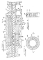
- Fig. 1 is a plan view in axial cross section of an extruder according to a first embodiment of the invention;
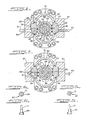
- Fig. 2 is a cross-sectional view taken along line 2-2 of Fig. 1;
- Fig. 3 is a cross-sectional view taken along line 3-3 of Fig. 1;
- Figs. 4a and 4b are end and side views, respectively, of one form of pins as shown in Figs. 1-2;
- Figs. 5a and 5b are end and side views, respectively, of another form of the pins as shown in Figs. 1-2;
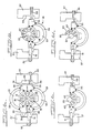
- Figs. 6a to 6d are views similar to Fig. 2, but showing how the parts of the extruder are disassembled;
- Fig. 7 is a radial cross-sectional view of a modified sleeve according to the invention; and
- Fig. 8 is a view taken along line 8-8 of Fig. 7.
- With reference to Fig. 1, an extruder includes an inlet section 11 into which rubber materials are fed, a main or
center section 13 in which the materials are mixed together, and ahead section 15 from which the mixture is extruded in a predetermined cross-sectional shape. - The
sections tubular casings cylindrical bores rotatable screw 23 extends through the bores. Thescrew 23 is journalled at both ends by bearings on thecasings - The
inlet casing 17 has itsbore 18 closed at its rear end by aclosure 24, and aninlet port 25 is formed in one side. Theport 25 is provided with afeeder 27 and a hopper (not shown) may be provided on the feeder. Thehead casing 21 has anopen front end 28. - As shown in Figs. 2-3, the
center casing 19 includes an outer axially extendingwall 29 which is oval in radial cross section, and an innercylindrical wall 31. Thecasing 19 is circumferentially divided into upper and lower halves. - Each casing half is formed with a
longitudinal passage 33 between the outer andinner walls - Each casing half also has a pair of
longitudinal flanges 35 projecting outwardly from theouter wall 29 on both side edges thereof. Provided adjacent theflanges 35 are a pair of longitudinally extendingclamps 37, each formed with alongitudinal groove 39 therein for engagement with theflanges 35 on one side of thecasing 19 when closed. Theclamps 37 engage taperedouter surfaces 36 of theflanges 35 and tightly secure the flanges (and the casings) together. The flanges, as shown in Fig. 2, are fastened to the outer and inner walls. - The
inner casing walls 31 surround atubular sleeve 41 which is circumferentially divided into two half circle parts, and the two parts are axially divided to form a plurality of axially aligned pairs ofarcuate segments 43. - The
screw 23 has a pair of spiral ribs ordouble male threads 45, which formspiral passages 47 for the rubber materials inside thesleeve 41. The outer surfaces of the threads are closely adjacent the inner surface of thesleeve 41. Thethreads 45 have a pitch which reduces gradually from therear end 24 of the inlet section 11 to the front end of themain section 13. The pitch reduction produces a gradual increase in pressure on the materials to heat and mix them. Thethreads 45 of a section of the screw within thecenter casting 13 are formed with axially spaced pairs of circumferentially alignednotches 49 therein. - As shown in Figs. 1-2, a plurality of
bolts 51 extend loosely through theclamps 37 and are threaded into thelower casing flanges 35. Threaded on thebolts 51 arenuts 52 for engagement with theclamps 37 to clamp the halves of thecasing 19 and thesegments 43. - Threaded holes are formed through the
clamps 37 and a plurality of releasingbolts 53 are threaded into the holes and engage thelower flanges 35. By screwing thebolts 53 in, the clamps are pushed away and released. Thebolts clamps 37, but only some of the bolts are shown in Fig. 1. - The
arcuate segments 43 of thesleeve 41 and theinner wall 31 of the upper casing half are formed with correspondingaxial grooves 55 for engagement with an axially extending key 57 (Figs. 2 and 6a) to normally fix them together and prevent relative rotation. Thegrooves 55 are positioned so as to angularly displace thediametrical border edges 59 of thesegments 43 away from theside flanges 37 of the casing, as shown in Fig. 2. - As shown in Fig. 3, a plurality of tightening
bolts 61 are threaded through one of thelower flanges 35, and extend through thecasing 19 in parallel with thebolts bolt 61 is provided for engagement with onearcuate segment 43 of each pair at an angular location away from theborder edges 59. Thebolts 61 can be passed throughholes 63 formed in theappropriate clamp 37, in order to more positively clamp thesegments 43 in addition to the clamping by theclamps 37. - As shown in Fig. 2, each
segment 43, except for those at both ends, is formed with a number of circumferentially alignedradial holes 65. Eachhole 65 has an inner bore portion and a radially outer counterbore which is increased in diameter relative to the inner bore. Theholes 65 are aligned with thenotches 49 of the threads of the screw. Through eachhole 65 extends apin 67. As shown in Figs. 4a, 4b, 5a and 5b, eachpin 67 has adouble diameter head 69 for rotatable engagement within ahole 65, and asmaller diameter leg 71 which projects radially inwardly from the associatedsegment 43 into onespiral passage 47. Theleg 71 is axially located to pass through thethread notches 49 when thescrew 23 rotates. This construction enables a larger number ofpins 67 to be provided for more uniform mixing of the materials. As shown in Figs. 4a and 5a, thelegs 71 preferably have a tapered or streamlined shape. - In operation, with reference to Fig. 1, the
screw 23 is rotated by a drive. Rubber materials are fed through theintake port 25 into the inlet section 11, and thrusted axially forwardly (toward the left) by thescrew 23 to themain section 13. In addition, because the pitch of thethreads 45 decreases in the forward direction, the materials are thrusted spirally forwardly along thepassages 47 with increasing pressure, and consequently kneaded and mixed. The materials then move in contact with the stationary (and rotatable) pins 67, which promote the mixing. - The materials move at various angles depending on the pitches of the
threads 45 and the firmness of the materials. As previously mentioned and as shown in Figs. 4a and 5a, thepins 71 are preferably streamlined or tapered, and the pins are rotatable in their holes. The flow of the processed material causes therotatable pins 67 to rotate to the positions where they have the minimum resistance to flow. This also reduces the loads on the pins. - The mixed material is extruded from the
open end 28 of thehead section 15 in a predetermined cross-sectional shape which is determined by this shape of theopening 28 or a die (not shown). - The
pins 67 may have a shape and/or length depending upon and suited to a specific type of material. The pins may be replaced depending on the nature of the material, or thesleeve 41 can be disassembled for inspection and repair, in the following manner: - The tightening bolts 61 (Fig. 3) and the nuts 52 (Figs. 1-2) are released.
- As shown in Fig. 6a, the releasing
bolts 53 are threaded into theclamps 37 to push the clamps from thecasing flanges 35. - As shown in Fig. 6b, the upper half of the
casing 19 and the key 57 are separated from the lower half and removed. - As shown in Fig. 6c, one or more pairs of
arcuate segments 43 are rotated by a necessary angle to the position where the upper segment is accessible, and the upper segment is removed. - As shown in Fig. 6d, the
lower segment 43 is then rotated upwardly and removed. - New pins and segments can then be assembled in the reverse order.
- The second embodiment shown in Figs. 7-8 differs from the first embodiment in that the second includes
arcuate segments 143 with a number offins 167, instead of the pins. Thefins 167 are formed integrally with and extend inwardly from the inner surfaces of thesegments 143, inwardly toward the screw (not shown) and the fins are at an angle with respect to the axis of thesegments 143 and the screw. The shape and direction of thefins 167 are predetermined depending on the pitch of the screw threads and the kind of the materials being processed. - In any of the embodiments, the
sleeve 41 may otherwise include a number of undivided rings (not shown) withoutpins 67 orfins 167, which are interposed between other axially shortened arcuate segments (also not shown) which are provided with pins or fins. Also, thesleeve 41 may be circumferentially divided into three or more arcuate segments instead of two as illustrated. - The major advantages of the extruder according to this invention are as follows:
- A. The main body of the apparatus can be disassembled and assembled, and particularly the sleeve having pins or fins can be replaced. This facilitates repair and inspection, and permits replacement with a sleeve having pins or fins suitable for the types of rubber materials to be processed.
- B. The heating/cooling
medium passages 33 are formed in the casing body, which is separate from the sleeve having pins or fins. This enables the passages to have a sufficiently large volume. Also, the pins do not extend through the passages, thus preventing the medium from leaking around pins.
Claims (4)
Applications Claiming Priority (2)
| Application Number | Priority Date | Filing Date | Title |
|---|---|---|---|
| JP76347/86 | 1986-04-01 | ||
| JP61076347A JPS62231719A (en) | 1986-04-01 | 1986-04-01 | Extruder of rubber material |
Publications (3)
| Publication Number | Publication Date |
|---|---|
| EP0240198A2 true EP0240198A2 (en) | 1987-10-07 |
| EP0240198A3 EP0240198A3 (en) | 1989-04-12 |
| EP0240198B1 EP0240198B1 (en) | 1992-08-12 |
Family
ID=13602820
Family Applications (1)
| Application Number | Title | Priority Date | Filing Date |
|---|---|---|---|
| EP19870302227 Expired - Lifetime EP0240198B1 (en) | 1986-04-01 | 1987-03-16 | Extruder for rubber materials |
Country Status (6)
| Country | Link |
|---|---|
| US (1) | US4723901A (en) |
| EP (1) | EP0240198B1 (en) |
| JP (1) | JPS62231719A (en) |
| KR (1) | KR930004047B1 (en) |
| CN (1) | CN1009908B (en) |
| DE (1) | DE3780996T2 (en) |
Cited By (1)
| Publication number | Priority date | Publication date | Assignee | Title |
|---|---|---|---|---|
| WO2008043329A2 (en) * | 2006-10-11 | 2008-04-17 | Harburg-Freudenberger Maschinenbau Gmbh | Extrusion device and method for producing the temperature-controlling regions of an extruder, and method for carrying out a laser cladding process |
Families Citing this family (28)
| Publication number | Priority date | Publication date | Assignee | Title |
|---|---|---|---|---|
| DE3772991D1 (en) * | 1987-08-21 | 1991-10-17 | Schumacher Walter | DEVICE FOR EXTRUDING, EXPANDING AND / OR THERMALLY TREATING SUBSTANCES AND SUBSTANCE MIXTURES. |
| CH674960A5 (en) * | 1988-06-10 | 1990-08-15 | Rcm Rubber Consulting Mach | |
| DE4010540C1 (en) * | 1990-04-02 | 1991-11-07 | Wilfried Dipl.-Ing. 3017 Pattensen De Baumgarten | |
| DE4012612A1 (en) * | 1990-04-20 | 1991-10-24 | Wilfried Baumgarten | SNAIL EXTRUDERS |
| DE4039942C1 (en) * | 1990-12-14 | 1992-01-30 | Berstorff Gmbh Masch Hermann | |
| US5304054A (en) * | 1991-04-19 | 1994-04-19 | Frenkel C-D Aktiengesellschaft | Plasticizing sections of cold feed rubber extruders |
| DE4141328C1 (en) * | 1991-12-14 | 1993-02-04 | Buss Ag, Basel, Ch | |
| US5219589A (en) * | 1992-01-22 | 1993-06-15 | Bridgestone/Firestone, Inc. | Vented kneading pin for extruder |
| DE4244312C1 (en) * | 1992-12-28 | 1994-01-20 | Baumgarten Wilfried | Screw extruder |
| US5749649A (en) * | 1996-03-05 | 1998-05-12 | Dynamic Mixers Inc. | Satellite extruder arrangement for polymer melt mixing with a dynamic mixer |
| CN1176877A (en) | 1997-09-03 | 1998-03-25 | 青岛化工学院 | Screw engaging feeding method for extruder |
| US6241375B1 (en) * | 1998-08-01 | 2001-06-05 | Peter Wang | Shear ring screw |
| US6250791B1 (en) * | 2000-06-16 | 2001-06-26 | Loren T. Schneider | Liner and pin assembly for use with an apparatus for kneading or mixing materials |
| JP2002122244A (en) * | 2000-10-16 | 2002-04-26 | Daicel Chem Ind Ltd | Shaft seal device |
| KR100415769B1 (en) * | 2002-02-22 | 2004-01-24 | 주식회사 동방이엔지 | Refuse derived fuel extruding machine |
| US20070062886A1 (en) * | 2005-09-20 | 2007-03-22 | Rego Eric J | Reduced pressure drop coalescer |
| FR2961116B1 (en) | 2010-06-14 | 2012-08-03 | Michelin Soc Tech | INSTALLATION AND METHOD FOR SYNCHRONIZATION OF AN INTERNAL MIXER |
| CN102173044B (en) * | 2011-02-24 | 2013-07-24 | 华南理工大学 | Blade extruding machine and load balancing and self-lubricating method for blades of blade extruding machine |
| AU2014354829B2 (en) | 2013-11-27 | 2019-01-17 | Tetra Laval Holdings & Finance S.A. | Cheese-making methods and apparatuses |
| DE202014002902U1 (en) | 2014-04-04 | 2014-04-29 | Blach Verwaltungs Gmbh & Co. Kg | Multi-screw extruder with an extruder housing |
| DE102014004865B4 (en) | 2014-04-04 | 2016-12-01 | Blach Verwaltungs Gmbh & Co. Kg | Multi-screw extruder with an extruder housing and insert for placement |
| EP3133914B1 (en) | 2014-04-21 | 2020-07-29 | Tetra Laval Holdings & Finance S.A. | Continuous cooker stretcher and method of use thereof |
| CN103921426B (en) * | 2014-05-05 | 2016-06-01 | 北京化工大学 | A kind of polymer melt infinitesimal analysis enhancement of heat transfer and mixing plasticizing extruder |
| EP3258775B1 (en) * | 2015-02-20 | 2020-12-02 | Tetra Laval Holdings & Finance S.A. | Single auger extruder |
| KR102436078B1 (en) * | 2016-12-21 | 2022-08-25 | 바스프 에스이 | Single-shaft extruder and method for altering morphology of a superabsorbent polymer gel (sap gel) using a single-shaft extruder |
| US11235526B2 (en) * | 2018-11-07 | 2022-02-01 | Seiko Epson Corporation | Plasticizing device, three-dimensional modeling device, and injection molding device |
| CN110696268A (en) * | 2019-08-29 | 2020-01-17 | 中宇环行(大连)发展有限公司 | Intelligent extrusion-injection molding integrated machine |
| DE102020214857A1 (en) | 2020-11-26 | 2022-06-02 | Continental Reifen Deutschland Gmbh | Apparatus for extruding a rubber compound having a Mooney viscosity greater than 50 MU and using the apparatus to extrude a first rubber compound into a second rubber compound and to extrude a third rubber compound into a fourth rubber compound |
Citations (11)
| Publication number | Priority date | Publication date | Assignee | Title |
|---|---|---|---|---|
| US1904884A (en) * | 1933-04-18 | royle | ||
| FR1133446A (en) * | 1954-05-17 | 1957-03-27 | Device for the extrusion of thermoplastics or the like | |
| US3458894A (en) * | 1966-09-13 | 1969-08-05 | Baker Perkins Inc | Mixing apparatus |
| FR2197635A1 (en) * | 1972-09-01 | 1974-03-29 | Werner & Pfleiderer | |
| DE2423785B1 (en) * | 1974-05-16 | 1975-09-11 | Werner & Pfleiderer, 7000 Stuttgart | Wear insert for the screw housing of a twin screw extruder or injection molding machine |
| US4178104A (en) * | 1972-07-21 | 1979-12-11 | Uniroyal, Ag | Method and apparatus for mixing viscous materials |
| US4385876A (en) * | 1978-05-31 | 1983-05-31 | Baker Perkins Inc. | Split wear liner for twin bore barrel assembly |
| EP0144192A1 (en) * | 1983-11-26 | 1985-06-12 | Farrel Corporation | Extruder barrel construction |
| EP0179315A2 (en) * | 1984-10-22 | 1986-04-30 | Windmöller & Hölscher | Single screw extruder for thermoplastics and elastomers |
| FR2580984A1 (en) * | 1985-04-30 | 1986-10-31 | Gumix Sa | Turbo-mixer extruder, the barrel of which is fitted with directing discs |
| DE3613612A1 (en) * | 1985-04-30 | 1986-11-06 | Gumix S.A., Barcelona | TURBOMIC EXTRUSION |
Family Cites Families (2)
| Publication number | Priority date | Publication date | Assignee | Title |
|---|---|---|---|---|
| GB614441A (en) * | 1946-04-15 | 1948-12-15 | Paul O Abbe Inc | Improvements in methods and apparatus for mixing, rendering plastic and reducing pulverulent materials |
| US3023455A (en) * | 1959-03-09 | 1962-03-06 | Herbert F Geier | Mixers |
-
1986
- 1986-04-01 JP JP61076347A patent/JPS62231719A/en active Granted
-
1987
- 1987-03-16 EP EP19870302227 patent/EP0240198B1/en not_active Expired - Lifetime
- 1987-03-16 DE DE8787302227T patent/DE3780996T2/en not_active Expired - Fee Related
- 1987-03-24 US US07/030,045 patent/US4723901A/en not_active Expired - Fee Related
- 1987-03-30 CN CN87102395A patent/CN1009908B/en not_active Expired
- 1987-04-01 KR KR1019870003091A patent/KR930004047B1/en not_active IP Right Cessation
Patent Citations (11)
| Publication number | Priority date | Publication date | Assignee | Title |
|---|---|---|---|---|
| US1904884A (en) * | 1933-04-18 | royle | ||
| FR1133446A (en) * | 1954-05-17 | 1957-03-27 | Device for the extrusion of thermoplastics or the like | |
| US3458894A (en) * | 1966-09-13 | 1969-08-05 | Baker Perkins Inc | Mixing apparatus |
| US4178104A (en) * | 1972-07-21 | 1979-12-11 | Uniroyal, Ag | Method and apparatus for mixing viscous materials |
| FR2197635A1 (en) * | 1972-09-01 | 1974-03-29 | Werner & Pfleiderer | |
| DE2423785B1 (en) * | 1974-05-16 | 1975-09-11 | Werner & Pfleiderer, 7000 Stuttgart | Wear insert for the screw housing of a twin screw extruder or injection molding machine |
| US4385876A (en) * | 1978-05-31 | 1983-05-31 | Baker Perkins Inc. | Split wear liner for twin bore barrel assembly |
| EP0144192A1 (en) * | 1983-11-26 | 1985-06-12 | Farrel Corporation | Extruder barrel construction |
| EP0179315A2 (en) * | 1984-10-22 | 1986-04-30 | Windmöller & Hölscher | Single screw extruder for thermoplastics and elastomers |
| FR2580984A1 (en) * | 1985-04-30 | 1986-10-31 | Gumix Sa | Turbo-mixer extruder, the barrel of which is fitted with directing discs |
| DE3613612A1 (en) * | 1985-04-30 | 1986-11-06 | Gumix S.A., Barcelona | TURBOMIC EXTRUSION |
Cited By (2)
| Publication number | Priority date | Publication date | Assignee | Title |
|---|---|---|---|---|
| WO2008043329A2 (en) * | 2006-10-11 | 2008-04-17 | Harburg-Freudenberger Maschinenbau Gmbh | Extrusion device and method for producing the temperature-controlling regions of an extruder, and method for carrying out a laser cladding process |
| WO2008043329A3 (en) * | 2006-10-11 | 2010-12-09 | Harburg-Freudenberger Maschinenbau Gmbh | Extrusion device and method for producing the temperature-controlling regions of an extruder, and method for carrying out a laser cladding process |
Also Published As
| Publication number | Publication date |
|---|---|
| EP0240198A3 (en) | 1989-04-12 |
| DE3780996T2 (en) | 1993-03-25 |
| EP0240198B1 (en) | 1992-08-12 |
| DE3780996D1 (en) | 1992-09-17 |
| JPH0344891B2 (en) | 1991-07-09 |
| US4723901A (en) | 1988-02-09 |
| KR930004047B1 (en) | 1993-05-19 |
| JPS62231719A (en) | 1987-10-12 |
| CN1009908B (en) | 1990-10-10 |
| CN87102395A (en) | 1987-10-14 |
| KR870009836A (en) | 1987-11-30 |
Similar Documents
| Publication | Publication Date | Title |
|---|---|---|
| US4723901A (en) | Extruder for rubber materials | |
| EP0509779B1 (en) | Improvements in cold feed rubber extruders | |
| TWI633002B (en) | Extruder screw and extruder and extrusion method | |
| US4779989A (en) | Transfer mixer assembly for use with an extruder screw of a polymer extruder or the like | |
| US5147198A (en) | High performance extruder with a constant number of threads in the inlet and outlet regions of a transfer shearing section | |
| US2765491A (en) | Extrusion apparatus | |
| US4697928A (en) | Modular mixing apparatus including interchangeable fluid processing means | |
| WO2015156230A1 (en) | Extruder screw, extruder and extrusion method | |
| EP0110694B1 (en) | Screw extruders | |
| US4447156A (en) | Modular mixing apparatus including interchangeable fluid processing means | |
| CN1076885A (en) | The continuous mixing and blending machine of multiscrew that is used for the plasticization mixture | |
| JPS5818138B2 (en) | continuous mixer | |
| US5590959A (en) | Continuous mixer and rotor segment removal tool for the same | |
| US7270471B2 (en) | Extruder | |
| KR20070083974A (en) | Extruder | |
| US4131368A (en) | Scrolls for extruding machines | |
| US5304054A (en) | Plasticizing sections of cold feed rubber extruders | |
| HUE025172T2 (en) | Kneading segment and kneading equipment | |
| US4696575A (en) | Single-screw extruder for producing thermoplastic and elastomeric products | |
| US4112516A (en) | Plasticizing device of an injection molding machine for plastics | |
| JP4348018B2 (en) | Twin screw extruder | |
| CA2094985A1 (en) | Screw element having shearing and scraping flights | |
| US4887907A (en) | Rotary extruder with internally cooled rotor | |
| JP4610826B2 (en) | Extruder cylinder | |
| JP3466497B2 (en) | Twin screw extruder |
Legal Events
| Date | Code | Title | Description |
|---|---|---|---|
| PUAI | Public reference made under article 153(3) epc to a published international application that has entered the european phase |
Free format text: ORIGINAL CODE: 0009012 |
|
| AK | Designated contracting states |
Kind code of ref document: A2 Designated state(s): DE FR GB IT |
|
| PUAL | Search report despatched |
Free format text: ORIGINAL CODE: 0009013 |
|
| AK | Designated contracting states |
Kind code of ref document: A3 Designated state(s): DE FR GB IT |
|
| 17P | Request for examination filed |
Effective date: 19890526 |
|
| 17Q | First examination report despatched |
Effective date: 19900824 |
|
| GRAA | (expected) grant |
Free format text: ORIGINAL CODE: 0009210 |
|
| AK | Designated contracting states |
Kind code of ref document: B1 Designated state(s): DE FR GB IT |
|
| PG25 | Lapsed in a contracting state [announced via postgrant information from national office to epo] |
Ref country code: FR Effective date: 19920812 |
|
| REF | Corresponds to: |
Ref document number: 3780996 Country of ref document: DE Date of ref document: 19920917 |
|
| RAP2 | Party data changed (patent owner data changed or rights of a patent transferred) |
Owner name: KOBE MACHINERY CO LTD |
|
| RIN2 | Information on inventor provided after grant (corrected) |
Free format text: SARUMARU, KAZUMASA |
|
| ITF | It: translation for a ep patent filed |
Owner name: MODIANO & ASSOCIATI S.R |
|
| REG | Reference to a national code |
Ref country code: DE Ref legal event code: 8580 Free format text: DER PATENTINHABER LAUTET RICHTIG: KOBE MACHINERY CO., LTD., KOBE, JP |
|
| EN | Fr: translation not filed | ||
| PLBE | No opposition filed within time limit |
Free format text: ORIGINAL CODE: 0009261 |
|
| STAA | Information on the status of an ep patent application or granted ep patent |
Free format text: STATUS: NO OPPOSITION FILED WITHIN TIME LIMIT |
|
| 26N | No opposition filed | ||
| PGFP | Annual fee paid to national office [announced via postgrant information from national office to epo] |
Ref country code: GB Payment date: 19970307 Year of fee payment: 11 |
|
| PGFP | Annual fee paid to national office [announced via postgrant information from national office to epo] |
Ref country code: DE Payment date: 19970321 Year of fee payment: 11 |
|
| PG25 | Lapsed in a contracting state [announced via postgrant information from national office to epo] |
Ref country code: GB Free format text: LAPSE BECAUSE OF NON-PAYMENT OF DUE FEES Effective date: 19980316 |
|
| GBPC | Gb: european patent ceased through non-payment of renewal fee |
Effective date: 19980316 |
|
| PG25 | Lapsed in a contracting state [announced via postgrant information from national office to epo] |
Ref country code: DE Free format text: LAPSE BECAUSE OF NON-PAYMENT OF DUE FEES Effective date: 19981201 |
|
| PG25 | Lapsed in a contracting state [announced via postgrant information from national office to epo] |
Ref country code: IT Free format text: LAPSE BECAUSE OF NON-PAYMENT OF DUE FEES;WARNING: LAPSES OF ITALIAN PATENTS WITH EFFECTIVE DATE BEFORE 2007 MAY HAVE OCCURRED AT ANY TIME BEFORE 2007. THE CORRECT EFFECTIVE DATE MAY BE DIFFERENT FROM THE ONE RECORDED. Effective date: 20050316 |