CN1009908B - Extruding apparatus for rubber material - Google Patents
Extruding apparatus for rubber material Download PDFInfo
- Publication number
- CN1009908B CN1009908B CN87102395A CN87102395A CN1009908B CN 1009908 B CN1009908 B CN 1009908B CN 87102395 A CN87102395 A CN 87102395A CN 87102395 A CN87102395 A CN 87102395A CN 1009908 B CN1009908 B CN 1009908B
- Authority
- CN
- China
- Prior art keywords
- casing
- screw rod
- pin
- lining
- sizing material
- Prior art date
- Legal status (The legal status is an assumption and is not a legal conclusion. Google has not performed a legal analysis and makes no representation as to the accuracy of the status listed.)
- Expired
Links
- 239000000463 material Substances 0.000 title claims abstract description 29
- 229920001971 elastomer Polymers 0.000 title abstract description 4
- 239000002826 coolant Substances 0.000 claims abstract description 8
- 238000010438 heat treatment Methods 0.000 claims abstract description 8
- 238000004513 sizing Methods 0.000 claims description 20
- 230000002093 peripheral effect Effects 0.000 abstract description 2
- 229920003052 natural elastomer Polymers 0.000 description 1
- 229920001206 natural gum Polymers 0.000 description 1
- 229920001194 natural rubber Polymers 0.000 description 1
- 229920000642 polymer Polymers 0.000 description 1
- 230000001105 regulatory effect Effects 0.000 description 1
- 238000007789 sealing Methods 0.000 description 1
- 238000004904 shortening Methods 0.000 description 1
- 238000003756 stirring Methods 0.000 description 1
Images

Classifications
-
- B—PERFORMING OPERATIONS; TRANSPORTING
- B29—WORKING OF PLASTICS; WORKING OF SUBSTANCES IN A PLASTIC STATE IN GENERAL
- B29C—SHAPING OR JOINING OF PLASTICS; SHAPING OF MATERIAL IN A PLASTIC STATE, NOT OTHERWISE PROVIDED FOR; AFTER-TREATMENT OF THE SHAPED PRODUCTS, e.g. REPAIRING
- B29C48/00—Extrusion moulding, i.e. expressing the moulding material through a die or nozzle which imparts the desired form; Apparatus therefor
- B29C48/25—Component parts, details or accessories; Auxiliary operations
- B29C48/78—Thermal treatment of the extrusion moulding material or of preformed parts or layers, e.g. by heating or cooling
- B29C48/80—Thermal treatment of the extrusion moulding material or of preformed parts or layers, e.g. by heating or cooling at the plasticising zone, e.g. by heating cylinders
- B29C48/83—Heating or cooling the cylinders
- B29C48/834—Cooling
-
- B—PERFORMING OPERATIONS; TRANSPORTING
- B29—WORKING OF PLASTICS; WORKING OF SUBSTANCES IN A PLASTIC STATE IN GENERAL
- B29C—SHAPING OR JOINING OF PLASTICS; SHAPING OF MATERIAL IN A PLASTIC STATE, NOT OTHERWISE PROVIDED FOR; AFTER-TREATMENT OF THE SHAPED PRODUCTS, e.g. REPAIRING
- B29C48/00—Extrusion moulding, i.e. expressing the moulding material through a die or nozzle which imparts the desired form; Apparatus therefor
- B29C48/25—Component parts, details or accessories; Auxiliary operations
- B29C48/256—Exchangeable extruder parts
- B29C48/2562—Mounting or handling of the die
-
- B—PERFORMING OPERATIONS; TRANSPORTING
- B29—WORKING OF PLASTICS; WORKING OF SUBSTANCES IN A PLASTIC STATE IN GENERAL
- B29C—SHAPING OR JOINING OF PLASTICS; SHAPING OF MATERIAL IN A PLASTIC STATE, NOT OTHERWISE PROVIDED FOR; AFTER-TREATMENT OF THE SHAPED PRODUCTS, e.g. REPAIRING
- B29C48/00—Extrusion moulding, i.e. expressing the moulding material through a die or nozzle which imparts the desired form; Apparatus therefor
- B29C48/25—Component parts, details or accessories; Auxiliary operations
- B29C48/36—Means for plasticising or homogenising the moulding material or forcing it through the nozzle or die
- B29C48/395—Means for plasticising or homogenising the moulding material or forcing it through the nozzle or die using screws surrounded by a cooperating barrel, e.g. single screw extruders
- B29C48/397—Means for plasticising or homogenising the moulding material or forcing it through the nozzle or die using screws surrounded by a cooperating barrel, e.g. single screw extruders using a single screw
-
- B—PERFORMING OPERATIONS; TRANSPORTING
- B29—WORKING OF PLASTICS; WORKING OF SUBSTANCES IN A PLASTIC STATE IN GENERAL
- B29C—SHAPING OR JOINING OF PLASTICS; SHAPING OF MATERIAL IN A PLASTIC STATE, NOT OTHERWISE PROVIDED FOR; AFTER-TREATMENT OF THE SHAPED PRODUCTS, e.g. REPAIRING
- B29C48/00—Extrusion moulding, i.e. expressing the moulding material through a die or nozzle which imparts the desired form; Apparatus therefor
- B29C48/25—Component parts, details or accessories; Auxiliary operations
- B29C48/36—Means for plasticising or homogenising the moulding material or forcing it through the nozzle or die
- B29C48/50—Details of extruders
- B29C48/505—Screws
- B29C48/64—Screws with two or more threads
- B29C48/645—Screws with two or more threads neighbouring threads and channels having identical configurations
-
- B—PERFORMING OPERATIONS; TRANSPORTING
- B29—WORKING OF PLASTICS; WORKING OF SUBSTANCES IN A PLASTIC STATE IN GENERAL
- B29C—SHAPING OR JOINING OF PLASTICS; SHAPING OF MATERIAL IN A PLASTIC STATE, NOT OTHERWISE PROVIDED FOR; AFTER-TREATMENT OF THE SHAPED PRODUCTS, e.g. REPAIRING
- B29C48/00—Extrusion moulding, i.e. expressing the moulding material through a die or nozzle which imparts the desired form; Apparatus therefor
- B29C48/25—Component parts, details or accessories; Auxiliary operations
- B29C48/36—Means for plasticising or homogenising the moulding material or forcing it through the nozzle or die
- B29C48/50—Details of extruders
- B29C48/68—Barrels or cylinders
- B29C48/6801—Barrels or cylinders characterised by the material or their manufacturing process
-
- B—PERFORMING OPERATIONS; TRANSPORTING
- B29—WORKING OF PLASTICS; WORKING OF SUBSTANCES IN A PLASTIC STATE IN GENERAL
- B29C—SHAPING OR JOINING OF PLASTICS; SHAPING OF MATERIAL IN A PLASTIC STATE, NOT OTHERWISE PROVIDED FOR; AFTER-TREATMENT OF THE SHAPED PRODUCTS, e.g. REPAIRING
- B29C48/00—Extrusion moulding, i.e. expressing the moulding material through a die or nozzle which imparts the desired form; Apparatus therefor
- B29C48/25—Component parts, details or accessories; Auxiliary operations
- B29C48/36—Means for plasticising or homogenising the moulding material or forcing it through the nozzle or die
- B29C48/50—Details of extruders
- B29C48/68—Barrels or cylinders
- B29C48/685—Barrels or cylinders characterised by their inner surfaces, e.g. having grooves, projections or threads
- B29C48/687—Barrels or cylinders characterised by their inner surfaces, e.g. having grooves, projections or threads having projections with a short length in the barrel direction, e.g. pins
-
- B—PERFORMING OPERATIONS; TRANSPORTING
- B29—WORKING OF PLASTICS; WORKING OF SUBSTANCES IN A PLASTIC STATE IN GENERAL
- B29C—SHAPING OR JOINING OF PLASTICS; SHAPING OF MATERIAL IN A PLASTIC STATE, NOT OTHERWISE PROVIDED FOR; AFTER-TREATMENT OF THE SHAPED PRODUCTS, e.g. REPAIRING
- B29C48/00—Extrusion moulding, i.e. expressing the moulding material through a die or nozzle which imparts the desired form; Apparatus therefor
- B29C48/25—Component parts, details or accessories; Auxiliary operations
- B29C48/78—Thermal treatment of the extrusion moulding material or of preformed parts or layers, e.g. by heating or cooling
- B29C48/80—Thermal treatment of the extrusion moulding material or of preformed parts or layers, e.g. by heating or cooling at the plasticising zone, e.g. by heating cylinders
- B29C48/83—Heating or cooling the cylinders
- B29C48/832—Heating
-
- B—PERFORMING OPERATIONS; TRANSPORTING
- B29—WORKING OF PLASTICS; WORKING OF SUBSTANCES IN A PLASTIC STATE IN GENERAL
- B29C—SHAPING OR JOINING OF PLASTICS; SHAPING OF MATERIAL IN A PLASTIC STATE, NOT OTHERWISE PROVIDED FOR; AFTER-TREATMENT OF THE SHAPED PRODUCTS, e.g. REPAIRING
- B29C48/00—Extrusion moulding, i.e. expressing the moulding material through a die or nozzle which imparts the desired form; Apparatus therefor
- B29C48/03—Extrusion moulding, i.e. expressing the moulding material through a die or nozzle which imparts the desired form; Apparatus therefor characterised by the shape of the extruded material at extrusion
-
- B—PERFORMING OPERATIONS; TRANSPORTING
- B29—WORKING OF PLASTICS; WORKING OF SUBSTANCES IN A PLASTIC STATE IN GENERAL
- B29K—INDEXING SCHEME ASSOCIATED WITH SUBCLASSES B29B, B29C OR B29D, RELATING TO MOULDING MATERIALS OR TO MATERIALS FOR MOULDS, REINFORCEMENTS, FILLERS OR PREFORMED PARTS, e.g. INSERTS
- B29K2021/00—Use of unspecified rubbers as moulding material
Abstract
The invention relates to an extruder including a casing which forms a cylindrical bore and a peripheral passage for a heating or cooling medium around the bore. A screw is mounted in the bore and axially fixed to the casing, but adapted to be rotated in the bore. The screw has a thread forming a spiral passage for rubber materials in the bore. A number of projections extend from the casing and into the spiral passage, and the thread is formed with notches for the projections to pass through as the screw rotates. A cylindrical sleeve is mounted within the casing and supports the projections. The casing and the sleeve are divided or split into at least two parts, and lock means is provided on the casing to lock the parts together during operation.
Description
The sizing material that the present invention relates to natural gum and rubber polymer mixes, evenly disperses and extrude a kind of extruder of usefulness.
Require priority application P2235784 as Japanese patent gazette 56-53500 that publishes on December 19th, 1981 and the West Germany that submitted on July 21st, 1972.Traditional extruder of 2 described these types, it comprises a casing that is processed with cylindrical bore, and endoporus holds a rotatable screw rod, and screw rod has formed the sizing material spiral groove channel in casing.Some mix pins and radially pass casing, stretch into length in the helicla flute so that can regulate pin.Some pins pass the space that is used for heating or cooling medium on the casing.Make a little breach on the screw flight, so that screw rod rotation the time passing through pin.
Traditional extruder of the above-mentioned type, the built-in length of regulating pin is a trouble, and this structural limitations the volume in cooling medium space.In addition, this medium may leak through the sealing around the pin.
Catalogue of the present invention provide a kind of extruding apparatus for rubber material, the mixing arrangement of its pin and so on can be shifted at an easy rate, so that obtain desirable built-in length and (pitch) at interval according to the classification of institute's processing materials, also is convenient to check and repair.
Another object of the present invention provides heating/cooling medium abundant flow volume, does not have a kind of like this extruder of dielectric leakage.
A further object of the invention provides and contains the spiral groove channel that reduces undesirable resistance in the Flow of Goods and Materials, thereby improves a kind of like this extruder of immixture.
According to extruder of the present invention, comprise that one is processed with cylindrical bore and casing by the peripheral channel of heating or cooling medium is arranged around the endoporus.One is contained in the endoporus and axially is contained on the casing and the screw rod that can rotate in endoporus.This screw flight forms the spiral groove channel of sizing material in endoporus.Some ledges stretch into spiral groove channel from casing, are processed with some breach on the screw thread, are used for passing through when screw rod rotates ledge.The cylindrical bush of supporting ledge is housed in casing.Casing is divided into lining or cuts two parts at least open, is provided with locking device on casing, so that when operation several parts are locked.
Now embodiments of the invention are illustrated by accompanying drawing, wherein:
Fig. 1 is the axial section plan view by the extruder of embodiment such as the present invention;
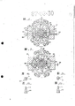
Fig. 2 is the profile along 2-2 line among Fig. 1;
Fig. 3 is the profile along 3-3 line among Fig. 1;
Fig. 4 a and Fig. 4 b are respectively the end-view and the side view of a kind of pin shown in Fig. 1-2;
Fig. 5 a and Fig. 5 b are respectively the end-view and the side view of another kind of pin shown in Fig. 1-2;
Fig. 6 a is the view of similar Fig. 2 to Fig. 6 b, but how to dismantle in order to the parts of expression extruder;
Fig. 7 is the axial section by the lining of the present invention's change;
Fig. 8 is the view along 8-8 line among Fig. 7.
With reference to Fig. 1, extruder comprises 11, one of the feeding sections of a feeding sizing material the major section of mixing of materials or central sections 13, and the head section 15 that sizing material is extruded by predetermined section configuration.
11,13 and 15 sections contain tubulose casing 17,19 and 21 respectively, and their headtotails are fixed into one.The cylindrical bores 18,20 and 22 that own centre line aligns in three sections casings also have a rotatable screw rod 23 through endoporus.Screw rod 23 is supported by the bearings at both ends of casing 17 and 21, and connects the running part (not shown) at the one end.
Feeding casing 17 has endoporus 18, is sealed by plug 24 in its back-end, and makes spout 25 in the one side.Mouth 25 is provided with feeding roller 27, can establish a loading hopper (not shown) on the feeding roller.Head casing 21 has a front opening 28.
Shown in Fig. 2-3, central casing 19 comprises an axially extended outer wall 29, and it is ovalize on radial section, also comprises a cylinder shape inner wall 31.Casing 19 circumferentially is divided into two halves up and down.
Make vertical passage 33 between the inside and outside wall 31 and 29 of per half casing, be used for the circulation heating/cooling medium so that material to be machined remains on the temperature of hope.
Per half casing also have a pair of from two sides of outer wall 29 outwardly directed longitudinal flange 35.Press close to flange 35 and be provided with a pair of clamp 37, cannelure 39 is all arranged on each, mesh with its a side and flange 35 when closed at casing 19.Clamp 37 meshes with the inclined outer surface 36 of flange 35, and two flanges (and casing) are tightened up together, and as shown in Figure 2, these flanges are fixed on the inside and outside wall.
Casing inner wall 31 is enclosed on the tubular liner 41 that circumferentially is divided into two semi-ring spares, and these two semi-ring spares axially are being divided into many countershafts to the arciform sector 43 that aligns again.
Screw rod 23 has a pair of spiral ridge or double end pin thread 45, and it forms the spiral groove channel 47 of sizing material in lining 41.The inner surface of the outer surface of screw thread and lining 41 leans on very closely.The front end of the pitch of screw thread 45 from the rear end 24 of feeding section 11 to central sections 13 progressively reduces.The reducing of pitch produced the pressure that sizing material is progressively increased, and makes its heating and mixes.The one section screw thread 45 of screw rod in central casing 13 is made to the breach in pairs 49 that axially-spaced is circumferentially made uniform.
Shown in Fig. 1-2, some bolts 51 are loosening passing clamp 37, are screwed in the lower casing flange 35.Nut 52 is screwed on the bolt 51, makes the sector 43 of clamp 37 chucking two halves casings 19.
Several dismountings are screwed into the screw that passes clamp 37 and withstand on lower casing flange 35 with bolt 53.Be screwed into bolt 53, clamp just is pushed out and dismantles.Bolt 51 and 53 length directions along clamp 37 are crisscross arranged, and only express a part of bolt among Fig. 1.
Arciform sector 43 and first casing inner wall 31 of lining 41 are processed with corresponding axial keyway 55, in order to embed axially extended key 57(Fig. 2 and 6a).They normally are fixed together can't relatively rotate.The position zero of keyway 55 makes the radial edges 59 slave shell-side face flanges 37 turn-off certain angles of sector 43.Resemble shown in Figure 2.
As shown in Figure 3, there are some fastening bolts 61 to be screwed into and to pass a lower flange 35, with the parallel casing 19 that passes of bolt 51 with 53.Each bolt 61 be used for every pair of arciform sector 43 in the middle of one be connected on the position that separates certain angle with edge 59 mutually.Bolt 61 can pass the hole 63 on the corresponding clamp 37, so that tighten sector 43 more reliably except that clamp 37 chuckings.
As shown in Figure 2, except each sector 43 two ends, other all makes the radial hole 65 of several circumferential centerings.There are internal holes and outside reaming radially in each hole 65, and outside reaming is bigger than diameter of bore.Align with screw flight breach 49 in hole 65.Pin 67 passes each hole 65 and stretches out.Shown in Fig. 4 a, 4b, 5a and 5b, the stem knob 69 that each pin 67 all has diameter to double, in order in the embedded hole 65 rotationally, the less pin leg 71 of its diameter inwardly radially reaches the spiral groove channel from the sector 43 that links to each other.The axial location of pin leg 71 is can pass thread gap 49 when screw rod 23 rotations.This structure can be provided with more pin 67, so that mixed material more equably.Shown in Fig. 4 a and 5a, pin leg 71 is wedge shape or streamlined preferably.
With reference to Fig. 1, screw rod 23 is driven in rotation at work.Sizing material is through spout 25 feeding feeding sections 11, by screw rod 23 axially forward (left) shift major section 13 onto.In addition, because of the pitch of screw thread 45 forwards to having reduced, along with the pressure that progressively increases, sizing material is pushed forward spirally along passage 47, thereby obtains stirring and mixing.So sizing material moves to fixing (and rotatable) pin 67 and contacts, and has encouraged immixture.
Sizing material moves with different angles by the pitch of screw thread 45 and the fastness of sizing material.As previously mentioned and shown in Fig. 4 a and 5a, pin 71 is streamlined or wedge shape preferably, and pin can rotate in their hole.Flowing of the sizing material of processing can cause that pin 67 rotates, and forwards the position that they have the flow resistance minimum to.This has also lowered the load of pin.
The sizing material that mixes is extruded from the opening 28 of head section 15 by predetermined section configuration.Section configuration is that the shape by an opening 28 or a shape of the mouth as one speaks (not shown) decides.
Unclamp fastening bolt 61(Fig. 3) and nut 52(Fig. 1-2).
Shown in Fig. 6 a, dismounting is screwed into clamp 37, clamp is released from casing flange 35 with bolt 53.Shown in Fig. 6 b, the first half of casing 19 is separated with the latter half with key 57 and is removed.
Shown in Fig. 6 c, a pair of or several angles to arciform sector 43 rotation necessity reach the easily detachable position of top sector, remove the top sector again.
Shown in Fig. 6 d, bottom sector 43 upwards rotates and removes.
So new pin and sector just can be pressed opposite assembled in sequence.
Second embodiment is illustrated among Fig. 7-8, and what be different from first embodiment is second and includes arciform sector 143, and the blade 167 of its band some is in order to replace pin.Blade 167 integral body make, and stretch out inwards at the inner surface of sector 143, stretch to the screw rod (not shown), and blade has certain angle with respect to the axial line of sector 143 and screw rod.The shape of blade 167 and direction are predetermined according to the pitch of screw flight and the kind of the sizing material of processing.
In these embodiment any, lining 41 may also comprise some not with the inseparable ring (not shown) of pin 67 or blade 167, and they are inserted between the arciform segment (not shown) of other axial shortening that has pin or blade.Lining 41 also can replace for example said two circumferentially being divided into three or more arciform sectors.
Major advantage by extruder of the present invention is as follows:
A. the Zhu body of this Zhuan Zhi can be dismantled, and particularly lining can be changed pin or blade. Zhe is convenient to repair and is checked, and can change the type that is fit to the sizing material of processing with the lining of pin or blade.
B. heating/coolant guiding channel 33 is on the processing Zai engine housing. It separates Yu lining with pin or blade. Zhe can make passage have the enough big volume of Zu. And pin do not pass passage, therefore prevented that medium from enclosing leakage from pin Zhou.
Claims (2)
1, a kind of extruder comprises a tubular casing, the outside of described casing has one to be used for the passage that heating or cooling medium flows, one cylindrical bush is contained in the casing and fixes wherein, one screw rod is supported in the casing and the coaxial with it extension in the lining inboard, described screw rod is suitable for rotation and has done screw thread thereon, form helical duct, be used for processing sizing material and make sizing material in lining along an axially-movable, on the circumference of lining, have radial hole, one pin all is housed in each hole, these pins have the pinning head and the leg of enlarged diameter, the pin leg extend in the described helical duct, screw thread on the screw rod has breach, allows pin pass through when rotating with convenient screw rod, and it is characterized in that: described housing is cylindrical parts in two, lining axially is being divided into some arciform sectors, locking device on the casing is used for releasably described parts being locked together, and each described radial hole all has an inner radial hole and outside reaming, and counter bore diameter increases to and can hold stem knob.
2, extruder according to claim 1 is characterized in that: the pitch of screw rod axially reduces gradually described.
Applications Claiming Priority (2)
| Application Number | Priority Date | Filing Date | Title |
|---|---|---|---|
| JP61076347A JPS62231719A (en) | 1986-04-01 | 1986-04-01 | Extruder of rubber material |
| JP76347/86 | 1986-04-01 |
Publications (2)
| Publication Number | Publication Date |
|---|---|
| CN87102395A CN87102395A (en) | 1987-10-14 |
| CN1009908B true CN1009908B (en) | 1990-10-10 |
Family
ID=13602820
Family Applications (1)
| Application Number | Title | Priority Date | Filing Date |
|---|---|---|---|
| CN87102395A Expired CN1009908B (en) | 1986-04-01 | 1987-03-30 | Extruding apparatus for rubber material |
Country Status (6)
| Country | Link |
|---|---|
| US (1) | US4723901A (en) |
| EP (1) | EP0240198B1 (en) |
| JP (1) | JPS62231719A (en) |
| KR (1) | KR930004047B1 (en) |
| CN (1) | CN1009908B (en) |
| DE (1) | DE3780996T2 (en) |
Cited By (1)
| Publication number | Priority date | Publication date | Assignee | Title |
|---|---|---|---|---|
| WO2016134372A1 (en) * | 2015-02-20 | 2016-08-25 | Johnson Industries International, Inc. | Single auger extruder |
Families Citing this family (28)
| Publication number | Priority date | Publication date | Assignee | Title |
|---|---|---|---|---|
| EP0303728B1 (en) * | 1987-08-21 | 1991-09-11 | Schumacher, Walter Dr. Ing. | Apparatus for extruding, expanding and/or thermally processing materials or material blends |
| CH674960A5 (en) * | 1988-06-10 | 1990-08-15 | Rcm Rubber Consulting Mach | |
| DE4010540C1 (en) * | 1990-04-02 | 1991-11-07 | Wilfried Dipl.-Ing. 3017 Pattensen De Baumgarten | |
| DE4012612A1 (en) * | 1990-04-20 | 1991-10-24 | Wilfried Baumgarten | SNAIL EXTRUDERS |
| DE4039942C1 (en) * | 1990-12-14 | 1992-01-30 | Berstorff Gmbh Masch Hermann | |
| US5304054A (en) * | 1991-04-19 | 1994-04-19 | Frenkel C-D Aktiengesellschaft | Plasticizing sections of cold feed rubber extruders |
| DE4141328C1 (en) * | 1991-12-14 | 1993-02-04 | Buss Ag, Basel, Ch | |
| US5219589A (en) * | 1992-01-22 | 1993-06-15 | Bridgestone/Firestone, Inc. | Vented kneading pin for extruder |
| DE4244312C1 (en) * | 1992-12-28 | 1994-01-20 | Baumgarten Wilfried | Screw extruder |
| US5749649A (en) * | 1996-03-05 | 1998-05-12 | Dynamic Mixers Inc. | Satellite extruder arrangement for polymer melt mixing with a dynamic mixer |
| CN1176877A (en) | 1997-09-03 | 1998-03-25 | 青岛化工学院 | Screw engaging feeding method for extruder |
| US6241375B1 (en) * | 1998-08-01 | 2001-06-05 | Peter Wang | Shear ring screw |
| US6250791B1 (en) * | 2000-06-16 | 2001-06-26 | Loren T. Schneider | Liner and pin assembly for use with an apparatus for kneading or mixing materials |
| JP2002122244A (en) * | 2000-10-16 | 2002-04-26 | Daicel Chem Ind Ltd | Shaft seal device |
| KR100415769B1 (en) * | 2002-02-22 | 2004-01-24 | 주식회사 동방이엔지 | Refuse derived fuel extruding machine |
| US20070062886A1 (en) * | 2005-09-20 | 2007-03-22 | Rego Eric J | Reduced pressure drop coalescer |
| DE102006048067A1 (en) * | 2006-10-11 | 2008-04-17 | Harburg-Freudenberger Maschinenbau Gmbh | Apparatus for extruding and the method for producing the tempering of an extruder |
| FR2961116B1 (en) * | 2010-06-14 | 2012-08-03 | Michelin Soc Tech | INSTALLATION AND METHOD FOR SYNCHRONIZATION OF AN INTERNAL MIXER |
| CN102173044B (en) * | 2011-02-24 | 2013-07-24 | 华南理工大学 | Blade extruding machine and load balancing and self-lubricating method for blades of blade extruding machine |
| US10426129B2 (en) | 2013-11-27 | 2019-10-01 | Tetra Laval Holdings & Finance S.A. | Cheese-making methods and apparatuses |
| DE102014004865B4 (en) | 2014-04-04 | 2016-12-01 | Blach Verwaltungs Gmbh & Co. Kg | Multi-screw extruder with an extruder housing and insert for placement |
| DE202014002902U1 (en) | 2014-04-04 | 2014-04-29 | Blach Verwaltungs Gmbh & Co. Kg | Multi-screw extruder with an extruder housing |
| AU2015249886B2 (en) | 2014-04-21 | 2018-12-06 | Tetra Laval Holdings & Finance S.A. | Continuous cooker stretcher and methods of use thereof |
| CN103921426B (en) * | 2014-05-05 | 2016-06-01 | 北京化工大学 | A kind of polymer melt infinitesimal analysis enhancement of heat transfer and mixing plasticizing extruder |
| KR102436078B1 (en) * | 2016-12-21 | 2022-08-25 | 바스프 에스이 | Single-shaft extruder and method for altering morphology of a superabsorbent polymer gel (sap gel) using a single-shaft extruder |
| CN111152451B (en) * | 2018-11-07 | 2021-08-24 | 精工爱普生株式会社 | Plasticizing device, three-dimensional molding device, and injection molding device |
| CN110696268A (en) * | 2019-08-29 | 2020-01-17 | 中宇环行(大连)发展有限公司 | Intelligent extrusion-injection molding integrated machine |
| DE102020214857A1 (en) | 2020-11-26 | 2022-06-02 | Continental Reifen Deutschland Gmbh | Apparatus for extruding a rubber compound having a Mooney viscosity greater than 50 MU and using the apparatus to extrude a first rubber compound into a second rubber compound and to extrude a third rubber compound into a fourth rubber compound |
Family Cites Families (13)
| Publication number | Priority date | Publication date | Assignee | Title |
|---|---|---|---|---|
| US1904884A (en) * | 1933-04-18 | royle | ||
| GB614441A (en) * | 1946-04-15 | 1948-12-15 | Paul O Abbe Inc | Improvements in methods and apparatus for mixing, rendering plastic and reducing pulverulent materials |
| NL187631B (en) * | 1954-05-17 | 1900-01-01 | Kali Chemie Ag | PROCEDURE FOR PREPARING MEDICINAL PRODUCTS THAT REDUCE OR REDUCE ANXIETY AND TENSION, AND PROCEDURE FOR PREPARING MEDICINAL COMPOUNDS SUITABLE FOR USE THEREIN. |
| US3023455A (en) * | 1959-03-09 | 1962-03-06 | Herbert F Geier | Mixers |
| US3458894A (en) * | 1966-09-13 | 1969-08-05 | Baker Perkins Inc | Mixing apparatus |
| US4178104A (en) * | 1972-07-21 | 1979-12-11 | Uniroyal, Ag | Method and apparatus for mixing viscous materials |
| DE2243039C3 (en) * | 1972-09-01 | 1980-08-14 | Werner & Pfleiderer, 7000 Stuttgart | Continuously working screw kneading mixer |
| DE2423785C2 (en) * | 1974-05-16 | 1980-06-12 | Werner & Pfleiderer, 7000 Stuttgart | Wear insert for the screw housing of a twin screw extruder or injection molding machine |
| US4385876A (en) * | 1978-05-31 | 1983-05-31 | Baker Perkins Inc. | Split wear liner for twin bore barrel assembly |
| GB2150037B (en) * | 1983-11-26 | 1986-11-12 | Farrel Bridge Ltd | Extruder barrel construction |
| DE3438649A1 (en) * | 1984-10-22 | 1986-04-24 | Windmöller & Hölscher, 4540 Lengerich | SINGLE SCREW EXTRUSION FOR THERMOPLASTIC AND ELASTOMERS |
| ES8607810A1 (en) * | 1985-04-30 | 1986-06-01 | Gumix Sa | Turbomixer-extruder machine |
| ES8607809A1 (en) * | 1985-04-30 | 1986-06-01 | Gumix Sa | Turbo-mixer extruder, the barrel of which is fitted with directing discs |
-
1986
- 1986-04-01 JP JP61076347A patent/JPS62231719A/en active Granted
-
1987
- 1987-03-16 DE DE8787302227T patent/DE3780996T2/en not_active Expired - Fee Related
- 1987-03-16 EP EP19870302227 patent/EP0240198B1/en not_active Expired - Lifetime
- 1987-03-24 US US07/030,045 patent/US4723901A/en not_active Expired - Fee Related
- 1987-03-30 CN CN87102395A patent/CN1009908B/en not_active Expired
- 1987-04-01 KR KR1019870003091A patent/KR930004047B1/en not_active IP Right Cessation
Cited By (1)
| Publication number | Priority date | Publication date | Assignee | Title |
|---|---|---|---|---|
| WO2016134372A1 (en) * | 2015-02-20 | 2016-08-25 | Johnson Industries International, Inc. | Single auger extruder |
Also Published As
| Publication number | Publication date |
|---|---|
| EP0240198A3 (en) | 1989-04-12 |
| JPH0344891B2 (en) | 1991-07-09 |
| US4723901A (en) | 1988-02-09 |
| EP0240198B1 (en) | 1992-08-12 |
| DE3780996T2 (en) | 1993-03-25 |
| DE3780996D1 (en) | 1992-09-17 |
| KR870009836A (en) | 1987-11-30 |
| CN87102395A (en) | 1987-10-14 |
| KR930004047B1 (en) | 1993-05-19 |
| EP0240198A2 (en) | 1987-10-07 |
| JPS62231719A (en) | 1987-10-12 |
Similar Documents
| Publication | Publication Date | Title |
|---|---|---|
| CN1009908B (en) | Extruding apparatus for rubber material | |
| US5145352A (en) | Pin transfer extruder | |
| EP0509779B1 (en) | Improvements in cold feed rubber extruders | |
| US7025491B2 (en) | Homogenizing and/or dispersing device comprising endless screws | |
| US5672005A (en) | Kneader | |
| US5114488A (en) | Extrusion method and apparatus for acid treatment of cellulosic materials | |
| CN1846972B (en) | Infinitely adjustable calibration sleeve for extruded plastic pipes | |
| EP0110694B1 (en) | Screw extruders | |
| EP1091798B1 (en) | Mixing device | |
| US5004352A (en) | Plasticizing screw | |
| US4643660A (en) | Screw extrusion press having barrel temperature control means | |
| US4708617A (en) | Screw extruder with a rotatable barrel section | |
| US4696575A (en) | Single-screw extruder for producing thermoplastic and elastomeric products | |
| US5304054A (en) | Plasticizing sections of cold feed rubber extruders | |
| US20070104815A1 (en) | Conveyor device | |
| US4450131A (en) | Zero runout counter-rotating film extruder | |
| US3833247A (en) | Breech-lock mechanism for extrusion apparatus | |
| CN1190310C (en) | Cylind for twin-screw extruder | |
| RU2108911C1 (en) | Screw extruder | |
| JP3589487B2 (en) | Viscous material extrusion equipment | |
| CN109397733B (en) | Automatic-control organic waste extrusion device | |
| CN1644352A (en) | Conic four-piece reciprocating pin scewrod extruder | |
| WO2023275964A1 (en) | A sealing device for a rotor shaft of a kneader | |
| WO2023275963A1 (en) | A sealing device for a rotor shaft of a kneader | |
| SU1705110A2 (en) | Polymeric material worm extrudes |
Legal Events
| Date | Code | Title | Description |
|---|---|---|---|
| C06 | Publication | ||
| PB01 | Publication | ||
| C10 | Entry into substantive examination | ||
| SE01 | Entry into force of request for substantive examination | ||
| C13 | Decision | ||
| GR02 | Examined patent application | ||
| C14 | Grant of patent or utility model | ||
| GR01 | Patent grant | ||
| C19 | Lapse of patent right due to non-payment of the annual fee | ||
| CF01 | Termination of patent right due to non-payment of annual fee |