EP0240023B1 - In einer Kunststoffkugel untergebrachte, opto-elektronische Anordnung - Google Patents
In einer Kunststoffkugel untergebrachte, opto-elektronische Anordnung Download PDFInfo
- Publication number
- EP0240023B1 EP0240023B1 EP87104909A EP87104909A EP0240023B1 EP 0240023 B1 EP0240023 B1 EP 0240023B1 EP 87104909 A EP87104909 A EP 87104909A EP 87104909 A EP87104909 A EP 87104909A EP 0240023 B1 EP0240023 B1 EP 0240023B1
- Authority
- EP
- European Patent Office
- Prior art keywords
- light
- emitting devices
- ring
- slit
- emitting
- Prior art date
- Legal status (The legal status is an assumption and is not a legal conclusion. Google has not performed a legal analysis and makes no representation as to the accuracy of the status listed.)
- Expired - Lifetime
Links
Images
Classifications
-
- G—PHYSICS
- G01—MEASURING; TESTING
- G01D—MEASURING NOT SPECIALLY ADAPTED FOR A SPECIFIC VARIABLE; ARRANGEMENTS FOR MEASURING TWO OR MORE VARIABLES NOT COVERED IN A SINGLE OTHER SUBCLASS; TARIFF METERING APPARATUS; MEASURING OR TESTING NOT OTHERWISE PROVIDED FOR
- G01D5/00—Mechanical means for transferring the output of a sensing member; Means for converting the output of a sensing member to another variable where the form or nature of the sensing member does not constrain the means for converting; Transducers not specially adapted for a specific variable
- G01D5/26—Mechanical means for transferring the output of a sensing member; Means for converting the output of a sensing member to another variable where the form or nature of the sensing member does not constrain the means for converting; Transducers not specially adapted for a specific variable characterised by optical transfer means, i.e. using infrared, visible, or ultraviolet light
Definitions
- the invention relates to an optoelectronic arrangement accommodated in a plastic ball, according to the preamble of claim 1, with which six components can be entered simultaneously, which in a Cartesian coordinate system have displacements in the X, Y and Z directions and angular rotations Dx, Dy and Dz are around these three axes.
- a plastic ball with the diameter of the human hand is preferably used, as is known from DE 32 40 251.
- a force-torque sensor known from DE 27 27 704 was used as the measuring system.
- a force and torque measuring method and associated manipulator are known from US-A-3 921 445.
- the translatory and the rotary movements around the three orthogonal manipulator axes are detected independently of one another by pairs of appropriately attached light sensors in diametrically opposite sensor units.
- a manipulator control mechanism is known from US-A-3 628 394, in which a ball housing is used.
- the invention is therefore intended to provide an optoelectronic arrangement which is compact in construction and easy to produce in comparison to the known force-torque sensors, with which distances and angular displacements are measured instead of forces and moments, and in which the measured values obtained are obtained by means of a simple electronics can be amplified and evaluated. According to the invention, this is achieved in an optoelectronic arrangement accommodated in a plastic ball according to the preamble of claim 1 by the features in the characterizing part of claim 1.
- Advantageous developments of the invention are the subject of dependent claims.
- At least six light-emitting devices are provided at the same angular distance from one another in a plane, to which slot diaphragms which are appropriately aligned at a predetermined distance are permanently assigned.
- a position-sensitive detector is arranged opposite each of the light-emitting devices in such a way that its detector axis is aligned perpendicular to the slot direction of the slot diaphragm assigned to it.
- the light-emitting devices with the slit diaphragms permanently assigned to them are relative the position-sensitive detectors are arranged to be movable relative to one another.
- the position-sensitive detectors are preferably arranged on the inside of a cylindrical ring, which in turn is firmly attached to the inside of the plastic ball.
- Spring elements preferably in the form of coil springs, are provided between the ring carrying the position-sensitive detectors and a holder device carrying the light-emitting devices in their center and are held, for example, by means of screw bolts so that the ring carrying the position-sensitive detectors with respect to the stationary holder device with the six light-emitting devices Devices and the permanently assigned six slit diaphragms can be moved so that the ring always returns to its starting position.
- the optoelectronic arrangement according to the invention can be very simple, extremely inexpensive and very small, i.e. compact and build, which eliminates the major disadvantages inherent in previous systems.
- each detector is individually assigned a very specific light-emitting device which is controlled by means of simple control electronics which keep the sum of the two currents flowing in the detector assigned to each light-emitting device constantly at a value which is common to all six systems of light-emitting device, assigned slit diaphragm and detector is the same.
- the radiation intensity of the light emitting devices is controlled, i.e. in the light-emitting devices, for example in the form of light-emitting diodes, the flow rate is regulated accordingly.
- All electronic components required for the regulation described above i.e. For processing, filtering, digitization and subsequent conversion of the measured values into the six Cartesian output signals, they can be accommodated in a plastic ball with a diameter of approximately 70 mm.
- the arrangement according to the invention has very good decoupling between the six components to be measured.
- the entire electronics can be integrated in the ball. Furthermore, no lens systems are required in the arrangement according to the invention, and no adjustment or calibration work is required.
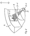
- a light-emitting device preferably in the form of a light-emitting diode 2-1, is attached to a mounting device 2, which is only indicated schematically.
- the light-emitting diode 2-1 is assigned, at a fixed predetermined distance, a slot diaphragm formed in a cylindrical ring 3, which in the detail of FIG. 2 is the horizontally running slot diaphragm 3-1.
- a position-sensitive detector (PSD) 4-1 is provided perpendicular to the slit direction of the respective slit diaphragm and is attached to a cylindrical ring 4 in the cutout shown in FIG. 2.
- FIG. 2 The elements shown in FIG. 2 and assigned to one another in the manner described, namely the light-emitting diode 2-1, the slit diaphragm 3-1 and the position-sensitive detector 4-1 arranged perpendicular to their slit direction form a basic measuring system, as it were the perspective view of FIG. 1 can be seen, is needed at least six times.
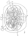
- the six light-emitting devices are arranged in one plane, the light-emitting devices each having a slit diaphragm 3-1 to 3-6 at a fixed distance assigned; adjacent slot diaphragms in the ring 3 are each offset by 90 °.
- the slit diaphragm 3-1 is horizontal and the two adjacent slit diaphragms 3-2 and 3-6 are aligned perpendicular to it; this relationship then also applies to all other slit diaphragms and the slit diaphragms which are adjacent to them.
- the at least six position-sensitive detectors 4-1 to 4-6 on a cylindrical ring 4 are correspondingly aligned with respect to the slit diaphragms 3-1 to 3-6 assigned to them. Furthermore, the ring 4 with the six detectors 4-1 to 4-6 is firmly attached to the inside of a plastic ball 1. Since the six light-emitting diodes 2-1 to 2-6 in FIG.
- a holding device 2 indicated schematically as a cylinder, which in turn is arranged stationary over a support 6, the ring 4, which is firmly connected to it, is attached to the plastic ball 1 the six detectors attached to it can be moved relative to the stationary arrangement of the six light-emitting devices 2-1 to 2-6 and the slit diaphragm ring 3 permanently assigned to them.
- the stationary mounting device 2 which is schematically indicated as a cylinder in FIG. 1, can be designed, for example, as a disk that is firmly connected to the stationary support 6, the diameter of which is approximately the outside diameter of the ring 4 that supports the detectors 4-1 to 4-6 corresponds and which can be arranged above or below this ring 4.
- spring elements preferably in the form of helical springs, are then provided between the ring 4 and the disk-shaped mounting device, which are firmly assigned to both the ring and the disk-shaped mounting device by means of screw bolts. It is then preferably achieved by such coil springs that the ring 4 carrying the detectors 4-1 to 4-6 can be moved over and over the plastic ball 1 with respect to the stationary arrangement of the light-emitting devices 2-1 to 2-6 and the permanently assigned slit diaphragm ring 3 returns to its starting position with every shift or angular rotation.
- shielding webs 5-1 to 5-6 running between them in the radial direction are shown for shielding the individual light-emitting diodes 2-1 to 2-6.
- Such webs can, however, be omitted if the individual light-emitting diodes are shielded from their own accord due to their design or due to a corresponding arrangement or placement on or in the mounting device 2, so that it is ensured that only light of the provided radially opposite light-emitting device is ensured via the slit diaphragm permanently assigned to it falls on the respective position-sensitive detector.
- the at least six basic measuring systems described with reference to Fig. 2 are at equal angular distances from one another, i.e. at an angle of 60 °, arranged in one plane, and, as already described, alternately to this plane horizontally and vertically aligned slit diaphragms 3-1 to 3-6.
- the detector axes of the individual position-sensitive detectors 4-1 to 4-6 are always perpendicular to those assigned to them Slotted diaphragms 3-1 to 3-6 aligned.
- a basic measurement system shown schematically and offset at least six times in the so-called measuring plane, achieves a complete detection of all six possible movement components, namely of three displacements in the direction of the three axes of the coordinate system and of three angular movements about these three axes.
- the at least six position-sensitive detectors 4-1 to 4-6 are attached to the cylindrical ring 4 in such a way that the zero point of their detector surfaces forms a common plane, the measurement plane already mentioned.
- the plastic ball 1 is fixedly attached to the ring 4 carrying the detectors 4-1 to 4-6, and since this ring 4, in turn, as detailed above, is preferably connected by means of spring elements to the stationary mounting device, which the arrangement from the carries six light-emitting devices 2-1 to 2-6 and the slit diaphragms 3-1 to 3-6 assigned to them, these spring elements keep the entire measuring system in the mechanical zero position if no commands are applied to the ball 1.
- the operating characteristics of the ball can be influenced within wide limits.
- the ball 1 acts more as a displacement-sensitive sensor, while when using harder spring elements, commands are issued more by exerting forces and moments.
- the position of interest of the light slit striking the respective position-sensitive detector can be determined from its two output currents (11, 12), which are previously converted into proportional voltages (U1, U2), via the known relationship (U1-U2) / (U1 + U2 ) determine. Analogously, however, this quotient can only be determined technically with a relatively large outlay.
- the detection as well as the digitization of the voltages U1 and U2 and the subsequent digital determination of the expression result in additional quantization errors, in particular if inexpensive converters with a low resolution are to be used.
- each position-sensitive detector is assigned its own light source, which is controlled by simple control electronics.
- the sum (11 + 12) of the two detector currents 11 and 12 is measured, and the radiation intensity of the assigned light source is controlled so that it is independent of the distance and the position of the assigned slit diaphragm (3-1 to 3-6) Sum always corresponds to a fixed value, whereby this value is the same for all at least six basic measuring systems.
- the desired position signal can then be determined in a simple, highly precise manner simply by forming a difference (U1-U2) between the two voltages U1 and U2 proportional to the output currents 11 and 12 of the detectors.
- the at least six position voltages UL1 to UL6 of the individual position-sensitive detectors 4-1 to 4-6 obtained in this way are digitized and fed to a microcomputer, which then calculates the total of six displacements and angular rotations using the simple equation system shown below:
- the optoelectronic arrangement according to the invention is also excellently suitable for high-precision positioning tasks, such as occur, for example, in robots and machine tools.
- the arrangement of the light-emitting devices and the diaphragm part permanently assigned to them, as well as the ring with the position-sensitive detectors are not connected with springs, but rather are attached separately to the two machine parts to be aligned.
- the optoelectronic arrangement according to the invention and the downstream control electronics the parts can then be aligned in all six degrees of freedom, or the remaining alignment errors can be determined with high precision.
- large-area detectors can also be used in order to obtain larger path and angle measuring ranges.
- the use of lens systems for bundling light beams or for imaging them on a detector surface can also be useful.
Landscapes
- Physics & Mathematics (AREA)
- General Physics & Mathematics (AREA)
- Length Measuring Devices By Optical Means (AREA)
- Photo Coupler, Interrupter, Optical-To-Optical Conversion Devices (AREA)
- Manipulator (AREA)
- Processing And Handling Of Plastics And Other Materials For Molding In General (AREA)
- Physical Or Chemical Processes And Apparatus (AREA)
- Polymerisation Methods In General (AREA)
- Pens And Brushes (AREA)
- Packaging Frangible Articles (AREA)
- Slot Machines And Peripheral Devices (AREA)
Priority Applications (1)
| Application Number | Priority Date | Filing Date | Title |
|---|---|---|---|
| AT87104909T ATE55642T1 (de) | 1986-04-04 | 1987-04-02 | In einer kunststoffkugel untergebrachte, optoelektronische anordnung. |
Applications Claiming Priority (2)
| Application Number | Priority Date | Filing Date | Title |
|---|---|---|---|
| DE19863611337 DE3611337A1 (de) | 1986-04-04 | 1986-04-04 | In einer kunststoffkugel untergebrachte, opto-elektronische anordnung |
| DE3611337 | 1986-04-04 |
Publications (2)
| Publication Number | Publication Date |
|---|---|
| EP0240023A1 EP0240023A1 (de) | 1987-10-07 |
| EP0240023B1 true EP0240023B1 (de) | 1990-08-16 |
Family
ID=6297941
Family Applications (1)
| Application Number | Title | Priority Date | Filing Date |
|---|---|---|---|
| EP87104909A Expired - Lifetime EP0240023B1 (de) | 1986-04-04 | 1987-04-02 | In einer Kunststoffkugel untergebrachte, opto-elektronische Anordnung |
Country Status (6)
| Country | Link |
|---|---|
| US (1) | US4785180A (ja) |
| EP (1) | EP0240023B1 (ja) |
| JP (1) | JPS6340803A (ja) |
| AT (1) | ATE55642T1 (ja) |
| DE (2) | DE3611337A1 (ja) |
| ES (1) | ES2016296B3 (ja) |
Cited By (4)
| Publication number | Priority date | Publication date | Assignee | Title |
|---|---|---|---|---|
| DE19952560A1 (de) * | 1999-11-01 | 2001-05-10 | Deutsch Zentr Luft & Raumfahrt | Verfahren zum Ein- und/oder Verstellen eines Sitzes, von Teilen des Sitzes und/oder von den Fahrer unterstützenden Vorrichtungen und Anordnung zur Durchführung des Verfahrens |
| DE19947733A1 (de) * | 1999-10-05 | 2001-08-09 | Deutsch Zentr Luft & Raumfahrt | Einrichtung zum Erfassen und Ermitteln von relevanten Kenndaten bezüglich eines einem Fahrzeugsitz zugeordneten, starren oder beweglichen Objekts sowie diesbezügliche Auswerteverfahren |
| DE10034569A1 (de) * | 2000-07-14 | 2002-01-31 | Deutsch Zentr Luft & Raumfahrt | Einrichtung zum Erfassen von Relativbewegungen eines Objekts |
| EP1291616A2 (de) | 2001-09-05 | 2003-03-12 | Deutsches Zentrum für Luft- und Raumfahrt e.V. | Anordnung zum Erfassen von Relativbewegungen zweier Objekte |
Families Citing this family (87)
| Publication number | Priority date | Publication date | Assignee | Title |
|---|---|---|---|---|
| DE3827719A1 (de) * | 1988-08-16 | 1990-02-22 | Dietmar Klinger | Optoelektronische messanordnung |
| US4952919A (en) * | 1989-04-06 | 1990-08-28 | Tektronix, Inc. | Trackball mechanism |
| DE4021455A1 (de) * | 1989-11-27 | 1991-05-29 | Stribel Gmbh | Optoelektronische einrichtung |
| US5359703A (en) * | 1990-08-02 | 1994-10-25 | Xerox Corporation | Moving an object in a three-dimensional workspace |
| DE4108388C2 (de) * | 1991-03-15 | 2000-10-12 | Wabco Gmbh & Co Ohg | Einrichtung zur berührungslosen Erfassung von mindestens zwei Positionen eines Schaltelementes |
| US5177352A (en) * | 1991-06-06 | 1993-01-05 | The United States Of America As Represented By The United States Department Of Energy | Integrated optical tamper sensor with planar waveguide |
| EP0594150A3 (en) * | 1992-10-20 | 1994-09-21 | Fuji Photo Film Co Ltd | An optical operation element and use thereof |
| DE4308456C2 (de) * | 1993-03-17 | 1996-03-28 | Ems Technik Gmbh | Vorrichtung zur Lagebestimmung eines Positionierkörpers relativ zu einem Bezugskörper |
| DE4409530C2 (de) * | 1993-03-19 | 1999-05-20 | Basys Ges Fuer Anwender Und Sy | Berührungslos arbeitende Meßeinrichtung und deren Verwendung zur Bestimmung des zweideimensional definierten Ortes eines Meßkörpers |
| DE4340941C2 (de) * | 1993-12-01 | 1996-07-11 | Stn Atlas Elektronik Gmbh | Bewegungsgeber zur simulierten Bewegung in einer virtuellen Umgebung |
| NL1003175C2 (nl) * | 1996-05-21 | 1997-11-25 | Wilhelmus Petrus Van Vliet | Mechanisch tastsysteem voorzien van een contactloos meetsysteem dat 6 vrijheidsgraden kan meten voor gebruik in coördinaten meetmachines, gereedschapsmachines en robots, geschikt om met hoge snelheid geometrische eigenschappen van werkstukken te bepalen. |
| DE19632273A1 (de) * | 1996-08-09 | 1998-02-12 | Helge Zwosta | Körpersensorik |
| AU4962997A (en) | 1996-12-04 | 1998-06-29 | Martin Sundin | Position measuring device for detecting displacements with at least three degrees of freedom |
| US6195083B1 (en) * | 1997-11-14 | 2001-02-27 | Septimiu E. Salcudean | Active joystick with optical positions sensor |
| DE19823903A1 (de) * | 1998-05-28 | 1999-12-02 | Sensor Instr Gmbh | Vorrichtung zum gleichzeitigen Messen eines an einer Welle wirksamen Drehmoments sowie des Drehwinkels der Welle |
| DE19937307A1 (de) * | 1998-08-10 | 2000-02-17 | Deutsch Zentr Luft & Raumfahrt | Verfahren zum Auslösen von technischen Steueroperationen und/oder zum Auslösen der Ausführung von technischen Funktionen sowie Anordnung zur Durchführung des Verfahrens |
| DE29901998U1 (de) * | 1999-02-05 | 2000-03-16 | Honeywell Ag | Vorrichtung zur Positionserfassung |
| DE10029173A1 (de) * | 2000-06-19 | 2002-01-03 | Deutsch Zentr Luft & Raumfahrt | Verfahren und Anordnung zum Kommandieren von Steuerungsoperationen für kinematische Bewegungen eines Objekts unter Verwendung eines von Hand betätigbaren Eingabegerätes |
| DE10045117C2 (de) * | 2000-09-13 | 2002-12-12 | Bernd Von Prittwitz | Verfahren und Vorrichtung zur Echtzeit-Geometriesteuerung |
| DE10125575A1 (de) * | 2001-05-25 | 2002-12-12 | Deutsch Zentr Luft & Raumfahrt | Eingabegerät mit einem personenbedienbaren Betätigungsteil zum Steuern der Positionierung eines Objekts |
| DE10158776B4 (de) * | 2001-11-30 | 2004-05-13 | 3Dconnexion Gmbh | Anordnung zum Erfassen von Relativbewegungen oder Relativpositionen zweier Objekte |
| DE10158775B4 (de) | 2001-11-30 | 2004-05-06 | 3Dconnexion Gmbh | Anordnung zum Erfassen von Relativbewegungen oder Relativpositionen zweier Objekte |
| DE10158777B4 (de) * | 2001-11-30 | 2004-05-06 | 3Dconnexion Gmbh | Anordnung zum Erfassen von Relativbewegungen oder Relativpositionen zweier Objekte |
| CN1692401B (zh) | 2002-04-12 | 2011-11-16 | 雷斯里·R·奥柏梅尔 | 多轴输入转换器装置和摇杆 |
| DE10246031A1 (de) * | 2002-10-02 | 2004-04-15 | 3Dconnexion Gmbh | Positions- und/oder Bewegungsfühler mit Überlastungsschutz |
| FR2847995B1 (fr) * | 2002-11-28 | 2005-05-13 | Ge Med Sys Global Tech Co Llc | Procede de traitement d'informations de commande transmises par un peripherique de manipulation d'images de modelisation 3d, et installation pour la visualisation d'images medicales en salle d'intervention et/ou d'examen |
| DE10325284A1 (de) * | 2003-06-04 | 2005-01-13 | 3Dconnexion Gmbh | Multidimensionales Eingabegerät zur Navigation und Selektion von vituellen Objekten |
| DE10334126B4 (de) * | 2003-07-25 | 2007-06-06 | 3Dconnexion Gmbh | Fehlerkorrektur bei Kraft-/Momentensensoren |
| DE102004064259B3 (de) | 2004-10-22 | 2018-03-08 | Société Civile "Galileo 2011" | Optoelektronische Anordnung zum Erfassen von Relativbewegungen oder Relativpositionen zweier Objekte |
| DE102004051565B4 (de) * | 2004-10-22 | 2014-06-26 | Société Civile "Galileo 2011" | Optoelektronische Anordnung zum Erfassen von Relativbewegungen oder Relativpositionen zweier Objekte sowie Kraft- und/oder Momentsensor, Pan/Zoom-Sensor und PC-Tastatur mit einer derartigen Anordnung |
| DE102004063975B4 (de) | 2004-10-22 | 2018-05-30 | Société Civile "Galileo 2011" | Optoelektronische Anordnung zum Erfassen von Relativbewegungen oder Relativpositionen zweier Objekte |
| EP1669842A1 (en) * | 2004-12-02 | 2006-06-14 | 3Dconnexion GmbH | Input device with different modes |
| DE102006008840B4 (de) * | 2006-02-25 | 2009-05-14 | Fraunhofer-Gesellschaft zur Förderung der angewandten Forschung e.V. | Beleuchtungsvorrichtung für zylindrische Objekte, damit durchgeführtes Oberflächenuntersuchungsverfahren und Computerprogrammprodukt |
| JP4955286B2 (ja) * | 2006-03-07 | 2012-06-20 | ミネベア株式会社 | 外力検出装置 |
| WO2008069068A1 (ja) | 2006-12-04 | 2008-06-12 | Shima Seiki Manufacturing, Ltd. | 3次元モーション入力器 |
| DE102006058806A1 (de) * | 2006-12-13 | 2008-06-19 | Spacecontrol Gmbh | Vorrichtung zum Messen von Beschleunigungen und Drehraten |
| DE102006058805B4 (de) * | 2006-12-13 | 2011-12-22 | Spacecontrol Gmbh | Vorrichtung zur Eingabe von Bewegungen und/oder Erfassung von Kräften |
| DE102008019144B4 (de) | 2008-04-16 | 2016-12-01 | Spacecontrol Gmbh | Vorrichtung zur Eingabe von Steuersignalen zum Bewegen eines Gegenstands |
| US9870021B2 (en) | 2009-04-15 | 2018-01-16 | SeeScan, Inc. | Magnetic manual user interface devices |
| WO2011146668A2 (en) | 2010-05-18 | 2011-11-24 | Seektech, Inc. | User interface devices, apparatus, and methods |
| EP3179330B1 (en) | 2010-08-20 | 2020-03-18 | SeeScan, Inc. | Magnetic sensing user interface device |
| WO2012051357A1 (en) | 2010-10-12 | 2012-04-19 | Mark Olsson | Magnetic thumbstick user interface devices |
| EP2665989B1 (en) | 2010-11-08 | 2019-12-25 | SeeScan, Inc. | Slim profile magnetic user interface devices |
| EP3043231A1 (en) | 2010-12-02 | 2016-07-13 | SeeScan, Inc. | Magnetically sensed user interface devices |
| DE102010062458A1 (de) | 2010-12-06 | 2012-06-06 | W. Gessmann Gmbh | Bedieneinrichtung zum Erzeugen von Anweisungen zur Steuerung der Bewegung eines reellen oder virtuellen Objektes |
| US9678577B1 (en) | 2011-08-20 | 2017-06-13 | SeeScan, Inc. | Magnetic sensing user interface device methods and apparatus using electromagnets and associated magnetic sensors |
| DE102011119014A1 (de) * | 2011-11-14 | 2013-05-16 | Jens Hansen | Schreibeinrichtung |
| EP2997453B1 (en) | 2013-05-17 | 2020-10-21 | SeeScan, Inc. | User interface devices |
| US9123506B2 (en) | 2013-06-10 | 2015-09-01 | Fei Company | Electron beam-induced etching |
| DE102017206025A1 (de) | 2017-04-07 | 2018-10-11 | Deutsches Zentrum für Luft- und Raumfahrt e.V. | Magnetische Anordnung zur Erfassung von Relativbewegungen oder Relativpositionen |
| DE102017110632A1 (de) | 2017-05-16 | 2018-11-22 | Deutsches Zentrum für Luft- und Raumfahrt e.V. | Eingabegerät sowie Verwendung eines solchen |
| US11428589B2 (en) * | 2017-10-16 | 2022-08-30 | Saf-Holland, Inc. | Displacement sensor utilizing ronchi grating interference |
| DE102018205159A1 (de) * | 2018-04-05 | 2019-10-10 | Deutsches Zentrum für Luft- und Raumfahrt e.V. | 3D-Eingabegerät |
| US11559298B2 (en) | 2018-07-16 | 2023-01-24 | Cilag Gmbh International | Surgical visualization of multiple targets |
| US10871384B2 (en) | 2019-02-26 | 2020-12-22 | Thomas P. Moyer | Apparatus and methods utilizing emissive patterns to determine positional information |
| US11690690B2 (en) | 2019-03-15 | 2023-07-04 | Cilag Gmbh International | Segmented control inputs for surgical robotic systems |
| US11471229B2 (en) | 2019-03-15 | 2022-10-18 | Cilag Gmbh International | Robotic surgical systems with selectively lockable end effectors |
| US11992282B2 (en) | 2019-03-15 | 2024-05-28 | Cilag Gmbh International | Motion capture controls for robotic surgery |
| US11213361B2 (en) | 2019-03-15 | 2022-01-04 | Cilag Gmbh International | Robotic surgical systems with mechanisms for scaling surgical tool motion according to tissue proximity |
| EP3937818A1 (en) | 2019-03-15 | 2022-01-19 | Cilag GmbH International | Input controls for robotic surgery |
| US11490981B2 (en) | 2019-03-15 | 2022-11-08 | Cilag Gmbh International | Robotic surgical controls having feedback capabilities |
| US11666401B2 (en) | 2019-03-15 | 2023-06-06 | Cilag Gmbh International | Input controls for robotic surgery |
| US11284957B2 (en) | 2019-03-15 | 2022-03-29 | Cilag Gmbh International | Robotic surgical controls with force feedback |
| US11583350B2 (en) | 2019-03-15 | 2023-02-21 | Cilag Gmbh International | Jaw coordination of robotic surgical controls |
| US12257013B2 (en) | 2019-03-15 | 2025-03-25 | Cilag Gmbh International | Robotic surgical systems with mechanisms for scaling camera magnification according to proximity of surgical tool to tissue |
| WO2020188391A1 (en) | 2019-03-15 | 2020-09-24 | Ethicon Llc | Robotic surgical controls having feedback capabilities |
| WO2021050199A1 (en) * | 2019-09-10 | 2021-03-18 | National Oilwell Varco, L.P. | Non-contact rotary communication system |
| US12002571B2 (en) | 2019-12-30 | 2024-06-04 | Cilag Gmbh International | Dynamic surgical visualization systems |
| US11744667B2 (en) | 2019-12-30 | 2023-09-05 | Cilag Gmbh International | Adaptive visualization by a surgical system |
| US12207881B2 (en) | 2019-12-30 | 2025-01-28 | Cilag Gmbh International | Surgical systems correlating visualization data and powered surgical instrument data |
| US11896442B2 (en) | 2019-12-30 | 2024-02-13 | Cilag Gmbh International | Surgical systems for proposing and corroborating organ portion removals |
| US11648060B2 (en) | 2019-12-30 | 2023-05-16 | Cilag Gmbh International | Surgical system for overlaying surgical instrument data onto a virtual three dimensional construct of an organ |
| US11832996B2 (en) | 2019-12-30 | 2023-12-05 | Cilag Gmbh International | Analyzing surgical trends by a surgical system |
| US12053223B2 (en) | 2019-12-30 | 2024-08-06 | Cilag Gmbh International | Adaptive surgical system control according to surgical smoke particulate characteristics |
| US11776144B2 (en) | 2019-12-30 | 2023-10-03 | Cilag Gmbh International | System and method for determining, adjusting, and managing resection margin about a subject tissue |
| US12453592B2 (en) | 2019-12-30 | 2025-10-28 | Cilag Gmbh International | Adaptive surgical system control according to surgical smoke cloud characteristics |
| US11284963B2 (en) | 2019-12-30 | 2022-03-29 | Cilag Gmbh International | Method of using imaging devices in surgery |
| US11759283B2 (en) | 2019-12-30 | 2023-09-19 | Cilag Gmbh International | Surgical systems for generating three dimensional constructs of anatomical organs and coupling identified anatomical structures thereto |
| US11219501B2 (en) | 2019-12-30 | 2022-01-11 | Cilag Gmbh International | Visualization systems using structured light |
| US11813746B2 (en) | 2020-12-30 | 2023-11-14 | Cilag Gmbh International | Dual driving pinion crosscheck |
| US12239404B2 (en) | 2020-12-30 | 2025-03-04 | Cilag Gmbh International | Torque-based transition between operating gears |
| US12070287B2 (en) | 2020-12-30 | 2024-08-27 | Cilag Gmbh International | Robotic surgical tools having dual articulation drives |
| US12059170B2 (en) | 2020-12-30 | 2024-08-13 | Cilag Gmbh International | Surgical tool with tool-based translation and lock for the same |
| DE102021106698A1 (de) | 2021-03-18 | 2022-09-22 | Deutsches Zentrum für Luft- und Raumfahrt e.V. | 3D-Eingabevorrichtung, Mobilgerät und 3D-Eingabegerät |
| WO2023073664A1 (en) | 2021-11-01 | 2023-05-04 | Cilag Gmbh International | Devices, systems, and methods for detecting tissue and foreign objects during a surgical operation |
| US11957342B2 (en) | 2021-11-01 | 2024-04-16 | Cilag Gmbh International | Devices, systems, and methods for detecting tissue and foreign objects during a surgical operation |
| US12137904B2 (en) | 2022-06-15 | 2024-11-12 | Cilag Gmbh International | Impact mechanism for grasp clamp fire |
Citations (2)
| Publication number | Priority date | Publication date | Assignee | Title |
|---|---|---|---|---|
| US3628394A (en) * | 1970-02-09 | 1971-12-21 | Sperry Rand Corp | Operator-manipulative control apparatus |
| US3921445A (en) * | 1973-10-15 | 1975-11-25 | Stanford Research Inst | Force and torque sensing method and means for manipulators and the like |
Family Cites Families (4)
| Publication number | Priority date | Publication date | Assignee | Title |
|---|---|---|---|---|
| DE2015982A1 (de) * | 1970-03-31 | 1971-10-14 | Siemens Ag | Einnchtung zur Erfassung meßwertent sprechender Auslenkungen eines Lichtstrahles |
| US3814199A (en) * | 1972-08-21 | 1974-06-04 | Cleveland Machine Controls | Motor control apparatus adapted for use with a motorized vehicle |
| DE2309682A1 (de) * | 1973-02-27 | 1974-09-26 | Messerschmitt Boelkow Blohm | Einrichtung zur erzeugung von signalen mit einem steuerknueppel |
| US4607159A (en) * | 1983-12-27 | 1986-08-19 | North American Philips Consumer Electronics Corp. | Optical joystick controller with intersecting spring means |
-
1986
- 1986-04-04 DE DE19863611337 patent/DE3611337A1/de not_active Withdrawn
-
1987
- 1987-04-01 US US07/033,512 patent/US4785180A/en not_active Expired - Lifetime
- 1987-04-01 JP JP62080872A patent/JPS6340803A/ja active Granted
- 1987-04-02 AT AT87104909T patent/ATE55642T1/de not_active IP Right Cessation
- 1987-04-02 DE DE8787104909T patent/DE3764287D1/de not_active Expired - Lifetime
- 1987-04-02 EP EP87104909A patent/EP0240023B1/de not_active Expired - Lifetime
- 1987-04-02 ES ES87104909T patent/ES2016296B3/es not_active Expired - Lifetime
Patent Citations (2)
| Publication number | Priority date | Publication date | Assignee | Title |
|---|---|---|---|---|
| US3628394A (en) * | 1970-02-09 | 1971-12-21 | Sperry Rand Corp | Operator-manipulative control apparatus |
| US3921445A (en) * | 1973-10-15 | 1975-11-25 | Stanford Research Inst | Force and torque sensing method and means for manipulators and the like |
Cited By (10)
| Publication number | Priority date | Publication date | Assignee | Title |
|---|---|---|---|---|
| DE19947733A1 (de) * | 1999-10-05 | 2001-08-09 | Deutsch Zentr Luft & Raumfahrt | Einrichtung zum Erfassen und Ermitteln von relevanten Kenndaten bezüglich eines einem Fahrzeugsitz zugeordneten, starren oder beweglichen Objekts sowie diesbezügliche Auswerteverfahren |
| DE19947733B4 (de) * | 1999-10-05 | 2004-04-29 | 3Dconnexion Gmbh | Einrichtung zum Erfassen und Auswerten von Kenndaten an einem Fahrzeugsitz sowie diesbezügliche Auswerteverfahren |
| DE19952560A1 (de) * | 1999-11-01 | 2001-05-10 | Deutsch Zentr Luft & Raumfahrt | Verfahren zum Ein- und/oder Verstellen eines Sitzes, von Teilen des Sitzes und/oder von den Fahrer unterstützenden Vorrichtungen und Anordnung zur Durchführung des Verfahrens |
| DE19952560C2 (de) * | 1999-11-01 | 2002-03-07 | Deutsch Zentr Luft & Raumfahrt | Verfahren zum Ein- und/oder Verstellen eines Kraftfahrzeugsitzes, von Teilen des Kraftfahrzeugsitzes und /oder von den Fahrer unterstützenden Einrichtungen und Vorrichtung zur Durchführung des Verfahrens |
| DE10034569A1 (de) * | 2000-07-14 | 2002-01-31 | Deutsch Zentr Luft & Raumfahrt | Einrichtung zum Erfassen von Relativbewegungen eines Objekts |
| DE10034569B4 (de) * | 2000-07-14 | 2004-02-12 | Deutsches Zentrum für Luft- und Raumfahrt e.V. | Einrichtung zum Erfassen von Relativbewegungen eines Objekts |
| EP1291616A2 (de) | 2001-09-05 | 2003-03-12 | Deutsches Zentrum für Luft- und Raumfahrt e.V. | Anordnung zum Erfassen von Relativbewegungen zweier Objekte |
| DE10143489A1 (de) * | 2001-09-05 | 2003-04-03 | Deutsch Zentr Luft & Raumfahrt | Anordnung zum Erfassen von Relativbewegungen zweier Objekte |
| DE10143489C2 (de) * | 2001-09-05 | 2003-07-17 | Deutsch Zentr Luft & Raumfahrt | Anordnung zum Erfassen von Relativbewegungen zweier Objekte |
| US6928886B2 (en) | 2001-09-05 | 2005-08-16 | Deutsches Zentrum Fur Luft-Und Raumfahrt E.V. | Arrangement for the detection of relative movements of two objects |
Also Published As
| Publication number | Publication date |
|---|---|
| JPH0457202B2 (ja) | 1992-09-10 |
| DE3764287D1 (de) | 1990-09-20 |
| EP0240023A1 (de) | 1987-10-07 |
| JPS6340803A (ja) | 1988-02-22 |
| ATE55642T1 (de) | 1990-09-15 |
| US4785180A (en) | 1988-11-15 |
| DE3611337A1 (de) | 1987-10-22 |
| ES2016296B3 (es) | 1990-11-01 |
Similar Documents
| Publication | Publication Date | Title |
|---|---|---|
| EP0240023B1 (de) | In einer Kunststoffkugel untergebrachte, opto-elektronische Anordnung | |
| EP1761363B1 (de) | Hilfsvorrichtung und Verfahren zum Einmessen einer an einem Manipulator montierbaren optischen Messanordnung | |
| DE2833272C3 (de) | Vorrichtung zur Bestimmung der Lage einer Strahlungsquelle | |
| EP0102472B1 (de) | Längen- oder Winkelmesseinrichtung | |
| EP3175949B1 (de) | Werkzeugmaschine | |
| EP1195580A2 (de) | Einrichtung zum Erfassen von Relativbewegungen eines Objekts | |
| EP0554711A1 (de) | Motorisches Stativ | |
| EP2729763A1 (de) | Korrektur und/oder vermeidung von fehlern bei der messung von koordinaten eines werkstücks | |
| EP0847149A1 (de) | Verfahren und Vorrichtung zum Ausrichten eines optischen Sende- und Empfangsstrahls bei Satellitenverbindungen | |
| WO2008071251A2 (de) | Vorrichtung zum erfassen von bewegungen und kräften | |
| DE69225847T2 (de) | Röntgenanalyseapparat | |
| DE68906669T2 (de) | Messsystem fuer eine werkzeugeinstellung in einer werkzeugmaschine. | |
| CH672679A5 (ja) | ||
| CH456407A (de) | Durch Schrittschaltmotore gesteuerte Profilkopiervorrichtung | |
| DE3702330A1 (de) | Vorrichtung zum steuern der richtung eines strahles einer optischen strahlung | |
| DE3614122C2 (ja) | ||
| DE3439495A1 (de) | Elektronisch stellbare nachgiebigkeit | |
| DE1270826B (de) | Geraet zur Raumabtastung | |
| DE3919917A1 (de) | Optischer sensor fuer die identifizierung eines koerpers | |
| CH496854A (de) | Einrichtung zur Ermittlung der Istlage einer Tunnelbohrmaschine in einem raumfesten Koordinatensystem | |
| EP0072386B1 (de) | Impulsgeber zum Erzeugen von elektronischen Impulsfolgen | |
| DE102010037580A1 (de) | Linearmotorpositionserfassungssystem | |
| EP0334033A1 (de) | Positionsregelung für sensorgeführte Portalroboter | |
| EP0092504A2 (de) | Faseroptische Messanordnung mit einem Geber und einer Messelektronik zur Lagemessung | |
| EP1137973B1 (de) | Verfahren und anordnung zur verringerung temperaturbedingter massabweichungen bei parallel angeordneten messsystemen |
Legal Events
| Date | Code | Title | Description |
|---|---|---|---|
| PUAI | Public reference made under article 153(3) epc to a published international application that has entered the european phase |
Free format text: ORIGINAL CODE: 0009012 |
|
| AK | Designated contracting states |
Kind code of ref document: A1 Designated state(s): AT DE ES FR GB IT NL SE |
|
| 17P | Request for examination filed |
Effective date: 19880507 |
|
| 17Q | First examination report despatched |
Effective date: 19890807 |
|
| RAP1 | Party data changed (applicant data changed or rights of an application transferred) |
Owner name: DEUTSCHE FORSCHUNGSANSTALT FUER LUFT- UND RAUMFAHR |
|
| GRAA | (expected) grant |
Free format text: ORIGINAL CODE: 0009210 |
|
| AK | Designated contracting states |
Kind code of ref document: B1 Designated state(s): AT DE ES FR GB IT NL SE |
|
| REF | Corresponds to: |
Ref document number: 55642 Country of ref document: AT Date of ref document: 19900915 Kind code of ref document: T |
|
| ITF | It: translation for a ep patent filed | ||
| REF | Corresponds to: |
Ref document number: 3764287 Country of ref document: DE Date of ref document: 19900920 |
|
| GBT | Gb: translation of ep patent filed (gb section 77(6)(a)/1977) | ||
| ET | Fr: translation filed | ||
| PLBE | No opposition filed within time limit |
Free format text: ORIGINAL CODE: 0009261 |
|
| STAA | Information on the status of an ep patent application or granted ep patent |
Free format text: STATUS: NO OPPOSITION FILED WITHIN TIME LIMIT |
|
| 26N | No opposition filed | ||
| ITTA | It: last paid annual fee | ||
| EAL | Se: european patent in force in sweden |
Ref document number: 87104909.4 |
|
| REG | Reference to a national code |
Ref country code: GB Ref legal event code: IF02 |
|
| PGFP | Annual fee paid to national office [announced via postgrant information from national office to epo] |
Ref country code: DE Payment date: 20060320 Year of fee payment: 20 |
|
| PGFP | Annual fee paid to national office [announced via postgrant information from national office to epo] |
Ref country code: NL Payment date: 20060419 Year of fee payment: 20 |
|
| PGFP | Annual fee paid to national office [announced via postgrant information from national office to epo] |
Ref country code: FR Payment date: 20060420 Year of fee payment: 20 |
|
| PGFP | Annual fee paid to national office [announced via postgrant information from national office to epo] |
Ref country code: SE Payment date: 20060424 Year of fee payment: 20 Ref country code: AT Payment date: 20060424 Year of fee payment: 20 |
|
| PGFP | Annual fee paid to national office [announced via postgrant information from national office to epo] |
Ref country code: GB Payment date: 20060426 Year of fee payment: 20 |
|
| PGFP | Annual fee paid to national office [announced via postgrant information from national office to epo] |
Ref country code: ES Payment date: 20060428 Year of fee payment: 20 |
|
| PGFP | Annual fee paid to national office [announced via postgrant information from national office to epo] |
Ref country code: IT Payment date: 20060430 Year of fee payment: 20 |
|
| PG25 | Lapsed in a contracting state [announced via postgrant information from national office to epo] |
Ref country code: GB Free format text: LAPSE BECAUSE OF EXPIRATION OF PROTECTION Effective date: 20070401 |
|
| PG25 | Lapsed in a contracting state [announced via postgrant information from national office to epo] |
Ref country code: NL Free format text: LAPSE BECAUSE OF EXPIRATION OF PROTECTION Effective date: 20070402 |
|
| PG25 | Lapsed in a contracting state [announced via postgrant information from national office to epo] |
Ref country code: ES Free format text: LAPSE BECAUSE OF EXPIRATION OF PROTECTION Effective date: 20070403 |
|
| REG | Reference to a national code |
Ref country code: GB Ref legal event code: PE20 |
|
| NLV7 | Nl: ceased due to reaching the maximum lifetime of a patent |
Effective date: 20070402 |
|
| EUG | Se: european patent has lapsed | ||
| REG | Reference to a national code |
Ref country code: ES Ref legal event code: FD2A Effective date: 20070403 |