EP0239779A2 - Anstichzündhütchen - Google Patents
Anstichzündhütchen Download PDFInfo
- Publication number
- EP0239779A2 EP0239779A2 EP87102519A EP87102519A EP0239779A2 EP 0239779 A2 EP0239779 A2 EP 0239779A2 EP 87102519 A EP87102519 A EP 87102519A EP 87102519 A EP87102519 A EP 87102519A EP 0239779 A2 EP0239779 A2 EP 0239779A2
- Authority
- EP
- European Patent Office
- Prior art keywords
- detonator
- ignition
- outer sleeve
- sleeve
- ignition element
- Prior art date
- Legal status (The legal status is an assumption and is not a legal conclusion. Google has not performed a legal analysis and makes no representation as to the accuracy of the status listed.)
- Granted
Links
Images
Classifications
-
- F—MECHANICAL ENGINEERING; LIGHTING; HEATING; WEAPONS; BLASTING
- F42—AMMUNITION; BLASTING
- F42C—AMMUNITION FUZES; ARMING OR SAFETY MEANS THEREFOR
- F42C19/00—Details of fuzes
- F42C19/08—Primers; Detonators
- F42C19/0815—Intermediate ignition capsules, i.e. self-contained primary pyrotechnic module transmitting the initial firing signal to the secondary explosive, e.g. using electric, radio frequency, optical or percussion signals to the secondary explosive
-
- F—MECHANICAL ENGINEERING; LIGHTING; HEATING; WEAPONS; BLASTING
- F42—AMMUNITION; BLASTING
- F42B—EXPLOSIVE CHARGES, e.g. FOR BLASTING, FIREWORKS, AMMUNITION
- F42B3/00—Blasting cartridges, i.e. case and explosive
- F42B3/10—Initiators therefor
- F42B3/16—Pyrotechnic delay initiators
-
- F—MECHANICAL ENGINEERING; LIGHTING; HEATING; WEAPONS; BLASTING
- F42—AMMUNITION; BLASTING
- F42C—AMMUNITION FUZES; ARMING OR SAFETY MEANS THEREFOR
- F42C19/00—Details of fuzes
- F42C19/08—Primers; Detonators
- F42C19/10—Percussion caps
Definitions
- the present invention relates to a detonator with a quick-release ignition element.
- the ignition element is sensitive to tapping or impact and acts on a delay set which, in turn, causes a downstream ignition agent to convert after reacting through.
- the firing element is formed with a primer in which the shock-sensitive primer is located in a one-piece well; after ignition of the ignition charge, the ignition gases or the flame penetrate through one or more ignition channels to the delay charge and cause it to ignite.
- a disadvantage of detonators with these ignition elements is the fact that the ignition charge is generally ignited by means of a spring-loaded ignition needle, which is very sensitive to shock, but often is pulled out of the detonator even before the end of the decay rate by the action of the spring force. This process relieves pressure and can lead to the extinguishing of the combustion process in the delay block, so that ignition failures occur.
- a mechanically releasable ignition element for igniting a delay set which is accommodated in a detonator sleeve with a downstream initial set and secondary charge, has been found and is characterized by the features specified in claim 1.
- the outer sleeve surrounding the ignition element is relatively thick-walled and has a thin bottom, the wall thickness of which can be between 0.05 and 0.15 mm.
- the side walls can increase in strength towards the bottom part; this increase takes place in such a way that the outer diameter of the sleeve remains constant, while the inner diameter becomes increasingly smaller towards the bottom, so that the radius of the thin bottom part becomes correspondingly smaller.
- the wall thickness at the base of the sleeve can be as large as the radius of the base part.
- the inner sleeve has an outer diameter that corresponds to the inner diameter of the outer sleeve. Its wall is positively attached to the inner wall of the outer shell. It is arranged coaxially within the outer sleeve so that its bottom forms a cavity with the bottom of the outer sleeve and its wall, in which the primer is arranged.
- the walls of the inner sleeve are thinner than the walls of the outer sleeve.
- the thickness of the bottom part corresponds approximately to the thickness of the bottom part of the outer sleeve.
- the wall thickness of the side walls is slightly larger than that of the bottom part.
- the open side opposite the base part can be bent inwards, so that this sleeve side, which is also referred to below as the sleeve mouth, has the shape of a disk with a circular opening.
- the side of the inner sleeve that is bent in this way rests positively directly on the correspondingly bent side of the outer sleeve.
- the diameter of the sleeve mouth of the outer sleeve corresponds to the diameter of the sleeve mouth of the inner sleeve.
- the inner diameter of both sleeves is preferably smaller than the height of the corresponding sleeve.
- the mouth of the inner sleeve preferably adjoins that of the outer sleeve.
- Metals, metal alloys or plastics can be used as the material for the inner and outer sleeve.
- Preferred materials are aluminum or brass.
- the cavity surrounded by the wall of the outer sleeve and the bottoms of the inner and outer sleeves contains a known primer consisting of oxidizing and reducing agents as well as quick-acting initial explosives.
- the proportion of the initial explosives in this primer is generally between 40 and 60% by weight, depending on the trigger sensitivity desired.
- the entire set can be used for fixing the components in loose form or bound by binders known per se.
- initial explosives examples include lead azide, diazodinitrophenol, lead trinitroresorcinate, tetrazene or azotetrazole in the form of its heavy metal salts.
- the entire igniter is arranged in the detonator so that the sleeve mouth points in the direction of the delay set. It is arranged coaxially with the latter within the detonator sleeve.
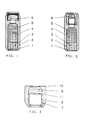
- Figure 1 shows a detonator according to the prior art
- Figure 2 shows the detonator according to the invention with igniter
- Figure 3 shows the igniter in an enlarged view, each in longitudinal section.
- 2 denotes the detonator sleeve, in which the ignition element 6 - formed in FIG. 1 as an ignition cap -, the delay set 5, the initial set 4 and the secondary charge 3 are arranged one behind the other.
- the secondary charge 3 is preferably covered with a cover plate 4.
- the outer sleeve is 7 and the inner sleeve 8.
- the ignition charge 9 is located between the outer and inner sleeve.
- the cavity in which this ignition charge is arranged is enclosed by the bottom wall 10 of the outer sleeve 7 and the bottom wall 11 of the inner sleeve 8 and the wall of the outer sleeve 7.
Landscapes
- Engineering & Computer Science (AREA)
- General Engineering & Computer Science (AREA)
- Air Bags (AREA)
- Graft Or Block Polymers (AREA)
Abstract
Description
- Gegenstand der vorliegenden Erfindung ist ein Detonator mit einem schnell auslösenden Anzündelement. Das Anzündelement ist anstich- bzw. schlagempfindlich und wirkt auf einen Verzögerungssatz ein, der seinerseits nach dem Durchreagieren einen nachgeschalteten Zündstoff zum Umsatz bringt.
- In den bekannten Detonatoren ist das Anzündelement ist Anzündhütchen ausgebildet, in dem sich der schlagempfindliche Zündsatz in einem einteiligen Näpfchen befindet; nach Zündung des Zündsatzes dringen die Zündgase bzw. die Flamme über einen oder mehrere Zündkanäle zu dem Verzögerungssatz und bringen diesen zur Zündung.
- Nachteilig bei Detonatoren mit diesen Anzündelementen wirkt sich der Umstand aus, daß die Zündung des Anzündsatzes im allgemeinen mittels einer gefederten Zündnadel erfolgt, die zwar sehr stoßempfindlich ist, jedoch oft bereits noch vor Ablauf der Abbrandzeit des Verzögerungssatzes durch Einwirkung der Federkraft wieder aus dem Detonator herausgerissen wird. Dieser Vorgang bewirkt eine Druckentlastung und kann zum Verlöschen des Abbrandvorganges im Verzögerungssatz führen, so daß es zu Zündversagern kommt. Diese Effekte werden besonders beim Aufprall auf ein nur geringes Hindernis, wie z.B. Strauchwerk oder Äste, beobachtet, während sie beim starken Aufprall des Zünders, z.B. auf harten Boden, dagegen kaum auftreten.
- Es bestand deshalb die Aufgabe, Detonatoren zu entwikkeln, die auch beim Aufschlag auf ein geringes Hindernis auch dann eine einwandfreie Zündung bewirken, wenn die Zündnadel aufgrund der auf sie einwirkenden Federkraft noch vor Ablauf des restlosen Abbrandes des Verzögerungssatzes aus dem Detonator wieder herausgerissen wird.
- In Erfüllung dieser Aufgabe wurde nun ein in einem Detonator angeordnetes, mechanisch auslösbares Anzündelement zum Zünden eines Verzögerungssatzes, der mit nachgeschaltetem Initialsatz und Sekundärladung in einer Detonatorhülse untergebracht ist, gefunden, der durch die im Patentanspruch 1 angegebenen Merkmale gekennzeichnet ist.
- Bei dieser erfindungsgemäßen Anordnung liegt ein gerichteter Zündkanal vor, der den Zündstrahl konzentriert bzw. gebündelt auf den Verzögerungssatz richtet, diesen äußerst schnell und zuverlässig zündet und die Anzündung und den Abbrand des Satzes von einer eventuellen vorzeitigen Druckentlasung infolge zurückgehender Zündnadel unabhängig macht.
- Die das Anzündelement umgebende Außenhülse ist relativ dickwandig und besitzt einen dünnen Boden, dessen Wandstärke zwischen 0,05 und 0,15 mm betragen kann. Die Seitenwände können zum Bodenteil hin an Stärke zunehmen; diese Zunahme erfolgt so, daß der Außendurchmesser der Hülse konstant bleibt, während der Innendurchmesser zum Boden hin zunehmend kleiner wird, so daß der Radius des dünnen Bodenteils entsprechend kleiner wird. Die Wandstärke am Boden der Hülse kann dabei so groß werden wie der Radius des düssen Bodenteils.
- Die Innenhülse hat einen Außendurchmesser, der dem Innendurchmesser der Außenhülse entspricht. Ihre Wandung liegt formschlüssig fest an der Innenwandung der Außenhülle. Sie ist koaxial innerhalb der Außenhülse so angeordnet, daß ihr Boden mit dem Boden der Außenhülse und deren Wandung einen Hohlraum bildet, in dem der Zündsatz angeordnet ist.
- Die Wandungen der Innenhülse sind dünner als die Wandungen der Außenhülse. Die Dicke des Bodenteils entspricht etwa der Dicke des Bodenteils der Außenhülse. Die Wandstärke der Seitenwände ist etwas größer als diejenige des Bodenteils.
- Sowohl bei der Innenhülse als auch bei der Außenhülse kann die offene, dem Bodenteil entgegengesetzt liegende Seite nach innen eingebogen werden, so daß diese Hülsenseite, die im folgenden auch als Hülsenmund bezeichnet wird, die Form einer Scheibe mit einer kreisförmigen Öffnung aufweist. In einer bevorzugten Duchführungsform der Erfindung liegt die auf diese Weise umgebogene Seite der Innenhülse formschlüssig direkt auf der entsprechend umgebogenen Seite der Außenhülse auf.
- Im allgemeinen entspricht der Durchmesser des Hülsenmundes der Außenhülse dem Durchmesser des Hülsenmundes der Innenhülse. Vorzugsweise ist bei beiden Hülsen der Innendurchmesser kleiner als die Höhe der entsprechenden Hülse. Der Mund der Innenhülse schließt sich vorzugsweise an denjenigen der Außenhülse an.
- Als Material für Innen- und Außenhülse kommen Metalle, Metallegierungen oder Kunststoffe in Frage. Bevorzugte Materialien sind Aluminium oder Messing.
- Der von der Wandung der Außenhülse und den Böden der Innen- und Außenhülse umgebene Hohlraum enthält einen an sich bekannten Zündsatz aus Oxidations- und Reduktionsmitteln sowie schnell wirksamen Initialsprengstoffen. Der Anteil der Initialsprengstoffe in diesem Zündsatz liegt im allgemeinen zwischen 40 und 60 Gew.-%, je nach gewünschter Auslöseempfindlichkeit. Der gesamte Satz kann sowohl in loser Form als auch durch an sich bekannte Bindemittel zur Fixierung der Komponenten gebunden eingesetzt sein.
- Beispiele für einsetzbare Initialsprengstoffe sind Bleiazid, Diazodinitrophenol, Bleitrinitroresorcinat, Tetrazen oder Azotetrazol in Form seiner Schwermetallsalze.
- Das gesamte Anzündelement ist in dem Detonator so angeordnet, daß der Hülsenmund in Richtung des Verzögerungssatzes weist. Er ist innerhalb der Detonatorhülse koaxial mit letzterer angeordnet.
- Anhand der beigefügten Zeichnungen wird die Erfindung beispielhaft dargestellt.
- Figur 1 zeigt einen Detonator entsprechend dem Stand der Technik, Figur 2 den erfindungsgemäßen Detonator mit Anzündelement und Figur 3 das Anzündelement in vergrößerter Darstellung, jeweils im Längsschnitt.
- In den Figuren wird mit 2 die Detonatorhülse bezeichnet, in der hintereinander angeordnet sind das Anzündelement 6 - in Figur 1 als Anzündhütchen ausgebildet -, der Verzögerungssatz 5, der Initialsatz 4 und die Sekundärladung 3. Die Sekundärladung 3 wird vorzugsweise mit einer Schlußscheibe 4 abgedeckt.
- In Figur 3 ist die Außenhülse mit 7 und die Innenhülse mit 8 bezeichnet. Zwischen Außen- und Innenhülse befindet sich der Zündsatz 9. Der Hohlraum, in dem dieser Zündsatz angeordnet ist, wird umschlossen von der Bodenwandung 10 der Außenhülse 7 und der Bodenwandung 11 der Innenhülse 8 sowie der Wandung der Außenhülse 7.
Claims (8)
Priority Applications (1)
| Application Number | Priority Date | Filing Date | Title |
|---|---|---|---|
| AT87102519T ATE91016T1 (de) | 1986-03-06 | 1987-02-23 | Anstichzuendhuetchen. |
Applications Claiming Priority (2)
| Application Number | Priority Date | Filing Date | Title |
|---|---|---|---|
| DE3607350 | 1986-03-06 | ||
| DE19863607350 DE3607350A1 (de) | 1986-03-06 | 1986-03-06 | Detonator mit schnell ausloesendem anzuendelement |
Publications (3)
| Publication Number | Publication Date |
|---|---|
| EP0239779A2 true EP0239779A2 (de) | 1987-10-07 |
| EP0239779A3 EP0239779A3 (en) | 1989-05-24 |
| EP0239779B1 EP0239779B1 (de) | 1993-06-23 |
Family
ID=6295643
Family Applications (1)
| Application Number | Title | Priority Date | Filing Date |
|---|---|---|---|
| EP87102519A Expired - Lifetime EP0239779B1 (de) | 1986-03-06 | 1987-02-23 | Anstichzündhütchen |
Country Status (7)
| Country | Link |
|---|---|
| US (1) | US4771693A (de) |
| EP (1) | EP0239779B1 (de) |
| AT (1) | ATE91016T1 (de) |
| DE (2) | DE3607350A1 (de) |
| ES (1) | ES2041248T3 (de) |
| IL (1) | IL81787A (de) |
| IN (1) | IN169176B (de) |
Families Citing this family (1)
| Publication number | Priority date | Publication date | Assignee | Title |
|---|---|---|---|---|
| US10989509B2 (en) * | 2017-10-05 | 2021-04-27 | Combined Systems, Inc. | Primer adapter assembly |
Family Cites Families (9)
| Publication number | Priority date | Publication date | Assignee | Title |
|---|---|---|---|---|
| DE310629C (de) * | ||||
| GB188606909A (en) * | 1886-05-22 | 1887-02-15 | Improvements in percussion caps and in the means for securing the same in cartridges | |
| US3195463A (en) * | 1962-07-19 | 1965-07-20 | Remington Arms Co Inc | Die cast battery cup and anvil |
| BE831139A (fr) * | 1975-07-08 | 1975-11-03 | Chambre d'amorce pour cartouche | |
| FR2355272A1 (fr) * | 1976-06-03 | 1978-01-13 | Manuf Gle Munitions | Dispositif d'amorcage pour munitions et analogues |
| US4315462A (en) * | 1979-09-10 | 1982-02-16 | Vollers Gary L | Shot gun shell primer |
| US4459914A (en) * | 1982-05-17 | 1984-07-17 | Caruso Anthony M | Impact-detonated time delay fuse |
| US4527481A (en) * | 1983-04-08 | 1985-07-09 | Ici Americas Inc. | Impact sensitive high temperature detonator |
| DE3446751A1 (de) * | 1984-12-21 | 1986-07-03 | Diehl GmbH & Co, 8500 Nürnberg | Anzuendmittel oder zuendmittel |
-
1986
- 1986-03-06 DE DE19863607350 patent/DE3607350A1/de active Granted
-
1987
- 1987-01-22 IN IN44/MAS/87A patent/IN169176B/en unknown
- 1987-02-23 AT AT87102519T patent/ATE91016T1/de not_active IP Right Cessation
- 1987-02-23 DE DE8787102519T patent/DE3786284D1/de not_active Expired - Fee Related
- 1987-02-23 EP EP87102519A patent/EP0239779B1/de not_active Expired - Lifetime
- 1987-02-23 ES ES198787102519T patent/ES2041248T3/es not_active Expired - Lifetime
- 1987-03-05 IL IL81787A patent/IL81787A/xx not_active IP Right Cessation
- 1987-03-06 US US07/022,961 patent/US4771693A/en not_active Expired - Lifetime
Also Published As
| Publication number | Publication date |
|---|---|
| ES2041248T3 (es) | 1993-11-16 |
| IN169176B (de) | 1991-09-14 |
| DE3607350A1 (de) | 1987-09-24 |
| US4771693A (en) | 1988-09-20 |
| IL81787A (en) | 1993-05-13 |
| DE3786284D1 (de) | 1993-07-29 |
| ATE91016T1 (de) | 1993-07-15 |
| DE3607350C2 (de) | 1991-10-17 |
| EP0239779B1 (de) | 1993-06-23 |
| IL81787A0 (en) | 1987-10-20 |
| EP0239779A3 (en) | 1989-05-24 |
Similar Documents
| Publication | Publication Date | Title |
|---|---|---|
| DE60021398T2 (de) | Zünder | |
| DE2637848C3 (de) | Zünder für einen Raketenmotor | |
| EP0718506A1 (de) | Durch eine Sprengladung verankerbarer Ankerbolzen | |
| DE2824703C2 (de) | Geschoß mit einem Durchschlagkörper | |
| DE2553717A1 (de) | Zuendvorrichtung | |
| EP0239779A2 (de) | Anstichzündhütchen | |
| DE1796082B1 (de) | Zuender fuer die punktfoermige Initiierung von Sprengladungen | |
| AT393322B (de) | Bodenzuender fuer eine granate | |
| DE2423921C2 (de) | Geschoß mit verzögerter Initiierung der Sprengladung | |
| DE3421841A1 (de) | Unterkalibrige uebungspatrone | |
| DE194343C (de) | ||
| DE4225394C2 (de) | Ein Brandelement enthaltende Granate | |
| DE2301957A1 (de) | Verzoegerungszuender fuer ein geschoss | |
| DE2426168C3 (de) | Mikrozeitzünder für Raketen | |
| DE60027676T2 (de) | Treibladungszünder für Artilleriemunition | |
| DE102020110916A1 (de) | Schlagbolzenanzünder | |
| CH654407A5 (de) | Verfahren und vorrichtung zum zuenden der treibladung in einer ein gas erzeugenden kartusche sowie kartusche mit der vorrichtung. | |
| DE219871C (de) | ||
| DE53771C (de) | Zünder für Geschosse | |
| DE224371C (de) | ||
| DE312110C (de) | ||
| AT47286B (de) | Wurfgranate. | |
| DE102018124363B4 (de) | Anzündeinheit mit einstellbarer Verzögerungszeit | |
| DE2920135A1 (de) | Vorrichtung zur zuendung einer zuendschnur, eines verzoegerungssatzes oder einer sprengkapsel | |
| DE198269C (de) |
Legal Events
| Date | Code | Title | Description |
|---|---|---|---|
| PUAI | Public reference made under article 153(3) epc to a published international application that has entered the european phase |
Free format text: ORIGINAL CODE: 0009012 |
|
| AK | Designated contracting states |
Kind code of ref document: A2 Designated state(s): AT BE CH DE ES FR GB GR IT LI SE |
|
| RAP1 | Party data changed (applicant data changed or rights of an application transferred) |
Owner name: HUELS TROISDORF AKTIENGESELLSCHAFT |
|
| RAP1 | Party data changed (applicant data changed or rights of an application transferred) |
Owner name: DYNAMIT NOBEL AKTIENGESELLSCHAFT |
|
| PUAL | Search report despatched |
Free format text: ORIGINAL CODE: 0009013 |
|
| AK | Designated contracting states |
Kind code of ref document: A3 Designated state(s): AT BE CH DE ES FR GB GR IT LI SE |
|
| 17P | Request for examination filed |
Effective date: 19890818 |
|
| 17Q | First examination report despatched |
Effective date: 19910125 |
|
| GRAA | (expected) grant |
Free format text: ORIGINAL CODE: 0009210 |
|
| ITF | It: translation for a ep patent filed | ||
| AK | Designated contracting states |
Kind code of ref document: B1 Designated state(s): AT BE CH DE ES FR GB GR IT LI SE |
|
| PG25 | Lapsed in a contracting state [announced via postgrant information from national office to epo] |
Ref country code: BE Effective date: 19930623 |
|
| REF | Corresponds to: |
Ref document number: 91016 Country of ref document: AT Date of ref document: 19930715 Kind code of ref document: T |
|
| REF | Corresponds to: |
Ref document number: 3786284 Country of ref document: DE Date of ref document: 19930729 |
|
| GBT | Gb: translation of ep patent filed (gb section 77(6)(a)/1977) |
Effective date: 19930701 |
|
| ET | Fr: translation filed | ||
| REG | Reference to a national code |
Ref country code: GR Ref legal event code: FG4A Free format text: 3008509 |
|
| REG | Reference to a national code |
Ref country code: ES Ref legal event code: FG2A Ref document number: 2041248 Country of ref document: ES Kind code of ref document: T3 |
|
| PG25 | Lapsed in a contracting state [announced via postgrant information from national office to epo] |
Ref country code: AT Effective date: 19940223 |
|
| PLBE | No opposition filed within time limit |
Free format text: ORIGINAL CODE: 0009261 |
|
| STAA | Information on the status of an ep patent application or granted ep patent |
Free format text: STATUS: NO OPPOSITION FILED WITHIN TIME LIMIT |
|
| 26N | No opposition filed | ||
| EAL | Se: european patent in force in sweden |
Ref document number: 87102519.3 |
|
| PGFP | Annual fee paid to national office [announced via postgrant information from national office to epo] |
Ref country code: SE Payment date: 19980126 Year of fee payment: 12 |
|
| PGFP | Annual fee paid to national office [announced via postgrant information from national office to epo] |
Ref country code: GR Payment date: 19980220 Year of fee payment: 12 |
|
| PGFP | Annual fee paid to national office [announced via postgrant information from national office to epo] |
Ref country code: ES Payment date: 19980227 Year of fee payment: 12 Ref country code: CH Payment date: 19980227 Year of fee payment: 12 |
|
| PG25 | Lapsed in a contracting state [announced via postgrant information from national office to epo] |
Ref country code: SE Free format text: LAPSE BECAUSE OF NON-PAYMENT OF DUE FEES Effective date: 19990224 Ref country code: ES Free format text: LAPSE BECAUSE OF NON-PAYMENT OF DUE FEES Effective date: 19990224 |
|
| PG25 | Lapsed in a contracting state [announced via postgrant information from national office to epo] |
Ref country code: LI Free format text: LAPSE BECAUSE OF NON-PAYMENT OF DUE FEES Effective date: 19990228 Ref country code: GR Free format text: LAPSE BECAUSE OF NON-PAYMENT OF DUE FEES Effective date: 19990228 Ref country code: CH Free format text: LAPSE BECAUSE OF NON-PAYMENT OF DUE FEES Effective date: 19990228 |
|
| REG | Reference to a national code |
Ref country code: CH Ref legal event code: PL |
|
| EUG | Se: european patent has lapsed |
Ref document number: 87102519.3 |
|
| REG | Reference to a national code |
Ref country code: ES Ref legal event code: FD2A Effective date: 20010910 |
|
| REG | Reference to a national code |
Ref country code: GB Ref legal event code: IF02 |
|
| PGFP | Annual fee paid to national office [announced via postgrant information from national office to epo] |
Ref country code: DE Payment date: 20020425 Year of fee payment: 16 |
|
| PGFP | Annual fee paid to national office [announced via postgrant information from national office to epo] |
Ref country code: GB Payment date: 20030130 Year of fee payment: 17 |
|
| PGFP | Annual fee paid to national office [announced via postgrant information from national office to epo] |
Ref country code: FR Payment date: 20030206 Year of fee payment: 17 |
|
| PG25 | Lapsed in a contracting state [announced via postgrant information from national office to epo] |
Ref country code: DE Free format text: LAPSE BECAUSE OF NON-PAYMENT OF DUE FEES Effective date: 20030902 |
|
| PG25 | Lapsed in a contracting state [announced via postgrant information from national office to epo] |
Ref country code: GB Free format text: LAPSE BECAUSE OF NON-PAYMENT OF DUE FEES Effective date: 20040223 |
|
| GBPC | Gb: european patent ceased through non-payment of renewal fee |
Effective date: 20040223 |
|
| PG25 | Lapsed in a contracting state [announced via postgrant information from national office to epo] |
Ref country code: FR Free format text: LAPSE BECAUSE OF NON-PAYMENT OF DUE FEES Effective date: 20041029 |
|
| REG | Reference to a national code |
Ref country code: FR Ref legal event code: ST |
|
| PG25 | Lapsed in a contracting state [announced via postgrant information from national office to epo] |
Ref country code: IT Free format text: LAPSE BECAUSE OF NON-PAYMENT OF DUE FEES;WARNING: LAPSES OF ITALIAN PATENTS WITH EFFECTIVE DATE BEFORE 2007 MAY HAVE OCCURRED AT ANY TIME BEFORE 2007. THE CORRECT EFFECTIVE DATE MAY BE DIFFERENT FROM THE ONE RECORDED. Effective date: 20050223 |