EP0239106A2 - Verfahren zum Verringern des NOX-Gehaltes in Gasen, bei welchem dem Gasstrom kontinuierlich NH3 zugesetzt wird - Google Patents
Verfahren zum Verringern des NOX-Gehaltes in Gasen, bei welchem dem Gasstrom kontinuierlich NH3 zugesetzt wird Download PDFInfo
- Publication number
- EP0239106A2 EP0239106A2 EP87104458A EP87104458A EP0239106A2 EP 0239106 A2 EP0239106 A2 EP 0239106A2 EP 87104458 A EP87104458 A EP 87104458A EP 87104458 A EP87104458 A EP 87104458A EP 0239106 A2 EP0239106 A2 EP 0239106A2
- Authority
- EP
- European Patent Office
- Prior art keywords
- gas
- values
- solid structure
- oxygen ion
- gas stream
- Prior art date
- Legal status (The legal status is an assumption and is not a legal conclusion. Google has not performed a legal analysis and makes no representation as to the accuracy of the status listed.)
- Granted
Links
Images


Classifications
-
- G—PHYSICS
- G05—CONTROLLING; REGULATING
- G05D—SYSTEMS FOR CONTROLLING OR REGULATING NON-ELECTRIC VARIABLES
- G05D21/00—Control of chemical or physico-chemical variables, e.g. pH value
- G05D21/02—Control of chemical or physico-chemical variables, e.g. pH value characterised by the use of electric means
-
- B—PERFORMING OPERATIONS; TRANSPORTING
- B01—PHYSICAL OR CHEMICAL PROCESSES OR APPARATUS IN GENERAL
- B01D—SEPARATION
- B01D53/00—Separation of gases or vapours; Recovering vapours of volatile solvents from gases; Chemical or biological purification of waste gases, e.g. engine exhaust gases, smoke, fumes, flue gases, aerosols
- B01D53/34—Chemical or biological purification of waste gases
- B01D53/74—General processes for purification of waste gases; Apparatus or devices specially adapted therefor
- B01D53/86—Catalytic processes
- B01D53/8621—Removing nitrogen compounds
- B01D53/8625—Nitrogen oxides
-
- G—PHYSICS
- G01—MEASURING; TESTING
- G01N—INVESTIGATING OR ANALYSING MATERIALS BY DETERMINING THEIR CHEMICAL OR PHYSICAL PROPERTIES
- G01N27/00—Investigating or analysing materials by the use of electric, electrochemical, or magnetic means
- G01N27/26—Investigating or analysing materials by the use of electric, electrochemical, or magnetic means by investigating electrochemical variables; by using electrolysis or electrophoresis
- G01N27/403—Cells and electrode assemblies
- G01N27/406—Cells and probes with solid electrolytes
- G01N27/407—Cells and probes with solid electrolytes for investigating or analysing gases
- G01N27/4073—Composition or fabrication of the solid electrolyte
- G01N27/4074—Composition or fabrication of the solid electrolyte for detection of gases other than oxygen
Definitions
- the invention relates to a method for reducing the NO x content in gases, wherein the gas stream is continuously added to NH3 and at least partially catalytically reduced by a catalytic converter, the NO x with NH3 during the flow of the gas.
- NO x means oxides of nitrogen, especially nitrogen monoxide and nitrogen dioxide (NO and NO2).
- NO and NO2 nitrogen monoxide and nitrogen dioxide
- the requirement to limit the nitrogen oxide emissions from power plant blocks to a maximum of 200 mg NO x per Nm3 is attempted to be met in that the nitrogen oxides in the exhaust gas by selective, catalytic reduction with the aid of an ammonia additive to the exhaust gas on a catalyst at 300 to 400 ° C as far as possible.
- the exact NH3 dosage especially when changing loads, creates difficulties.
- unreacted NH3 was found in the fly ash and also in the waste water.
- the object of the present invention is therefore to provide a method according to the preamble of claim 1, in which the dosage of NH3 to the gas stream so can be adapted to the NO x content of the gas stream that the unreacted NH3 content in the clean gas can be kept below 5 ppm and at the same time a NO x separation efficiency in practice of over 80% is guaranteed. It is a further object of the invention to provide a device with which the measured values for NH 3 in the clean gas required for carrying out the method according to the invention can be obtained quickly, safely and in a simple manner and thereby an accurate, flexible and continuous NH 3 metering into the exhaust gas the catalytic reduction of NO x is made possible.
- the electrode can either be in the form of a porous solid-state structure or a dense layer which is sufficiently thin because of the required oxygen transport, for example from a few atomic layers.
- a further development of the device according to the invention consists in that, in the case of several probes, at least one probe on the side facing the gas above the solid structure has a gas-permeable catalyst layer which accelerates the chemical conversion of a gas component and closes the gap between the oxygen-ion-conducting material and the solid structure.
- An alternative embodiment of the device according to the invention is characterized in that the probe has an element which separates the oxygen ion-conducting material from at least two parts and consists of material which is not a conductor of oxygen ions, on the side facing the gas, one part of the oxygen-ion-conducting material above the solid structure is provided with a layer which is inert to the gas components, and above the other parts above the solid structure is each provided with a catalyst layer which accelerates the chemical conversion of a gas component, the inert layer and the catalyst layer or layers are arranged individually or jointly to close the intermediate space to the oxygen ion-conducting material and to the solid structure and each part made of oxygen-conducting material has a separate electrical discharge.
- the solid structure can consist of one or more metals and one or more oxides of at least one transition metal from subgroups IV, V, VIII and I of the Periodic Table of the Elements.
- the NH3 residual concentrations to be investigated in the gas stream after the reduction of the NO x can be measured in a very wide concentration range, advantageously in concentration ranges between 0 and up to 1000 ppm, depending on the type of execution of the probe.
- the characteristics of the device according to the invention can be adjusted by appropriate selection of the type of electrodes and the operating temperature.
- the use of oxides and mixed oxides opens up many possibilities for the composition of the electrode.
- the continuous NH3 concentration monitoring can gasför undisturbed by others components in the gas stream. In each case, the change in oxygen activity is measured, which is dependent on the local composition of the interface of the oxide electrode which is in contact with the gas stream.
- Oxide electrodes which can be used with good success are, for example, Pt ⁇ V2O5, V2O5, Pt ⁇ CuO, TiO2 and Pt ⁇ Co3O4.
- Pt ⁇ V2O5 for measuring NH3 with simultaneous presence of CO
- NH3 can be selectively detected with the help of an upstream catalyst layer, which contains V2O5 ⁇ TiO2 on a substrate of Al2O3 ⁇ MgO ⁇ SiO2 as an active component.
- FIGS. 1 to 4 show different examples of the schematic structure of useful versions of the solid chains. Only the probe heads or the parts of the electrochemical cells that are in contact with the gas mixture (sample gas) are listed, computers and control units are not shown.
- FIGS. 5 to 15 show results and mode of operation of the invention when applied to exemplary experiments.
- Figure 1 shows the head of a single measuring probe 1, consisting essentially of a tube closed on one side from a solid electrolyte 2, z. B. from zirconia stabilized with yttrium oxide, from one on the inside 4 the reference gas 6, for example air, facing metal electrode 13, for example made of platinum, from a porous solid structure 7 arranged on the surface 3 of the solid electrolyte 2 (or the oxygen ion-conducting material) facing the measuring gas as measuring electrode, which either consists of one or more Oxides or one or more metallic and one or more oxidic components, and two electrical leads 10 and 11 from the surface 3 of the solid electrolyte facing the measuring gas or the surface 4 facing the reference gas 6 to the computer.
- the electrical leads 10 and 11 can consist, for example, of gold conductor tracks.
- FIG. 2 shows a section from the area of the surface 3 of the solid electrolyte 2 facing the measuring gas 5 with part of the porous solid structure 7 arranged thereon.
- FIG. 2 is based on a version of the solid structure 7 which has two metallic components 8 and 8a and an oxidic one Component 9 has.
- the one metallic component 8 consists of platinum and the additionally applied component 8a, which at least partially covers the platinum surface, consists of rhodium.
- the oxidic component can consist of V2O5, for example. While the thickness of the solid electrolyte layer 2 between the two electrodes can be approximately 1 mm, the solid structure 7 can have a total thickness of approximately 5 ⁇ m.
- Figure 3 shows two spatially separate probe heads 1 and 1 ⁇ with the leads 10, 10 ⁇ and 11, 11 ⁇ .
- the one probe head 1 is configured as already described, the other probe head 1 ⁇ has a gas-permeable catalyst layer 12 over the porous solid structure 7, which closes the space between the oxygen ion-conducting material 2 and the solid structure 7 in an airtight manner.
- the catalyst layer 12 can be designed as a tablet and with a ceramic adhesive 14 on the Measuring gas 5 facing surface 3 of the solid electrolyte.
- the catalyst tablet consists of a reaction NO + NH3 ⁇ N2 + H2O accelerating material, the actual concentration of NH3 in the gas compared to the NH3 concentration of approximately 0 is measured on the probe 1 ⁇ in the presence of NO and NH3 in the measuring gas 5 at the probe 1.
- FIG. 4 shows another version of the device according to the invention, in which two solid chains are combined in one probe and separated by an element 23 made of inert material.
- the two solid chains of this probe 21 are arranged on a tube 34 made of an insulating oxide ceramic.
- a porous tablet 32, 33 is arranged above the solid structure 27 of the two half cells, one half 32 of which consists of a catalyst layer, the other half 33 of which consists of inert material.
- the electrical signal can be detected via the leads 30 on the side of the catalyst layer and 31 on the side of the inert material.
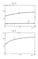
- a gas mixture of nitrogen plus 3% by volume of oxygen was mixed with NH3 in the following concentrations: NH3: 10, 20, 50, 100 and 200 ppm All gas mixtures were examined with probes which had TiO2 (Fig. 5, curve 53), V2O5 (Fig. 6, curve 63) or Co3O4 (Fig. 5, curve 73) as oxide electrodes.
- the operating temperature was 450 ° C.
- the probe signals obtained in mV are shown depending on the concentrations.
- probes which contained oxide electrodes made of Pt ⁇ CuO (Fig. 7, curve 83) or Pt ⁇ Co3O4 (Fig. 7, curve 93), gas mixtures of nitrogen and 3% by volume oxygen and certain concentrations were obtained from NH3: 10, 20, 50, 100, 200 and 500 ppm at a temperature of 450 ° C for the respective probe signals in mV, depending on the concentrations.
- the dashed straight line shows as the tangent of the first part of curve 113 / I the rise of this curve in the range from 0 to 10 ppm NH3 and demonstrates the quality of the Pt ⁇ V2O5 electrode with 4 mV / ppm NH3.
- the dashed line shows the rise of curve 123 / I in the range from 0 to 10 ppm NH3, which takes a steeper course with 7 mV / ppm NH3 than the corresponding part of curve 113 / I in Figure 8.
- NH3 in the concentrations 10, 20, 50, 100, 300 and 500 ppm and 2.
- CO in the concentrations 100, 200, 300 and 500 ppm brought with a device from two separate probes (A) and with a probe from two half cells (B) at 450 ° C for measurement.
- the probe signals determined in mV, depending on the concentration of the admixtures, can be seen from FIG. 12: with the probes used, CO was neither used with the one device variant (2 separate probes: curve 104 A) nor with the other (probe with two half cells: curve 104 B) received for monitoring signals.
- the electrode material consisted of Pt ⁇ V2O5, the second probe 1 ⁇ or the second half cell of probe 21 (see FIGS. 3 and 4) upstream catalyst made of V2O5 ⁇ TiO2 on Al2O3 ⁇ MgO ⁇ SiO2.
- the probe signals were measured in mV under comparable conditions, i.e. H. on the one hand for the gas mixture without NH3 addition (1), for the gas mixture plus 100 ppm NH3 (2) and for the gas mixture plus 1000 ppm NH3 (3) and on the other hand at temperatures that gradually increase starting at 450 ° C initially by 100 ° were then lowered again by the same difference down to 350 ° C. Since the probes were prepared at a relatively low temperature of 450 ° C. before the temperature cycle was run through, it can be expected that, as shown in FIGS. 13 to 15, the high temperature treatment has an influence on the probe characteristics. Above all, these measurements show that, depending on the temperature, NH 3 can be measured in different concentration ranges.
Landscapes
- Chemical & Material Sciences (AREA)
- Engineering & Computer Science (AREA)
- Health & Medical Sciences (AREA)
- General Physics & Mathematics (AREA)
- Life Sciences & Earth Sciences (AREA)
- Environmental & Geological Engineering (AREA)
- Chemical Kinetics & Catalysis (AREA)
- Physics & Mathematics (AREA)
- Analytical Chemistry (AREA)
- Pathology (AREA)
- Biomedical Technology (AREA)
- Immunology (AREA)
- Biochemistry (AREA)
- Electrochemistry (AREA)
- Automation & Control Theory (AREA)
- Molecular Biology (AREA)
- General Health & Medical Sciences (AREA)
- General Chemical & Material Sciences (AREA)
- Oil, Petroleum & Natural Gas (AREA)
- Treating Waste Gases (AREA)
- Exhaust Gas Treatment By Means Of Catalyst (AREA)
- Investigating Or Analyzing Non-Biological Materials By The Use Of Chemical Means (AREA)
- Investigating Or Analyzing Materials By The Use Of Fluid Adsorption Or Reactions (AREA)
- Industrial Gases (AREA)
Abstract
Description
- Die Erfindung betrifft ein Verfahren zum Verringern des NOx-Gehaltes in Gasen, bei welchem dem Gasstrom kontinuierlich NH₃ zugesetzt und während des Durchströmens des Gases durch einen katalytischen Konverter das NOx mit dem NH₃ mindestens zum Teil katalytisch reduziert wird.
- Die Probleme, die NOx-Emissionen in die Luft, beispielsweise aus Großfeuerungsanlagen, mit sich bringen und eine Reihe von Maßnahmen zur Minderung dieser NOx-Emissionen sind allgemein bekannt. Unter NOx werden Oxide des Stickstoffes, vornämlich Stickstoffmonoxid und Stickstoffdioxid (NO und NO₂), verstanden. Die Forderung, den Stickoxid-Ausstoß von Kraftwerksblöcken auf maximal 200 mg NOx pro Nm³ zu begrenzen, wird versucht dadurch zu erfüllen, daß die Stickoxide im Abgas durch eine selektive, katalytische Reduktion mit Hilfe eines Ammoniakzusatzes zum Abgas an einem Katalysator bei 300 bis 400° C möglichst weitgehend entfernt werden. Hierbei bereitet jedoch die genaue NH₃-Dosierung, insbesondere bei Lastwechsel, Schwierigkeiten. Unter anderem wurde nicht umgesetztes NH₃ in der Flugasche und auch im Abwasser festgestellt. Eine Beschränkung des nicht umgesetzten NH₃ im Reingas (nach der NOx-Entfernung) auf Werte unter 5 ppm brachte eine Beschränkung des chemischen NOx-Umsatzes auf Werte unter 80 % des ursprünglichen Gehaltes im Abgas mit sich. Eine einfache, sichere, im Hinblick auf den sich verändernden NOx-Gehalt im Abgasstrom flexible, kontinuierliche NH₃-Dosierung, welche die Nachteile der bekannten Verfahren vermeidet, ist bisher nicht bekannt geworden.
- Aufgabe der vorliegenden Erfindung ist es daher, ein Verfahren nach dem Gattungsbegriff des Patentanspruches 1 bereitzustellen, bei welchem die Dosierung des NH₃ zum Gasstrom so angepaßt werden kann an den NOx-Gehalt des Gasstroms, daß der nicht umgesetzte NH₃-Gehalt im Reingas auf Werte unter 5 ppm gehalten werden kann und gleichzeitig ein NOx-Abscheidegrad in der Praxis von über 80 % gewährleistet ist. Es ist weiterhin Aufgabe der Erfindung eine Vorrichtung zu schaffen, mit welcher die für die Durchführung des erfindungsgemäßen Verfahrens erforderlichen Meßwerte für NH₃ im Reingas rasch, sicher und auf einfache Weise erhalten werden und hierdurch eine genaue, flexible und kontinuierliche NH₃-Dosierung in das Abgas vor der katalytischen Reduktion des NOx ermöglicht wird.
- Die Aufgabe wird erfindungsgemäß gelöst durch
- a) kontinuerliche Messung des NH₃-Gehaltes im Gasstrom an einer Stelle nach der katalytischen Reduktion von NOx mit Hilfe mindestens einer elektrochemischen Zelle mit mindestens einer Festkörperkette, welche Sauerstoffionen leitendes Material enthält und von der NH₃-Konzentration abhängige elektrische Signale erzeugt,
- b) selbsttätiges elektronisches Auswerten der Meßsignale in einem Rechner, Berechnung der NH₃-Konzentrationswerte aus den Meßsignalen und Vergleichen der berechneten NH₃-Konzentrationswerte mit den Werten eines zuvor in den Rechner eingegebenen Schemas und
- c) automatisches Steuern des Flusses der NH₃-Zugabe zum Gasstrom vor der katalytischen Reduktion durch den Rechner nach Maßgabe der Unterschiede der berechneten Werte von den Werten des Schemas.
- Die erfindungsgemäße Vorrichtung zur Durchführung des Verfahrens, welche einen Rechner, Steuerelemente und eine Meßeinheit umfaßt, welche aus einer oder mehreren Gassonden mit Sauerstoffionen leitendem, mit dem Gas in Kontakt stehendem Material mit Elektroden auf der dem Gas zugewandten Fläche und der dem Gas abgewandten Fläche und mit den erforderlichen elektrischen Ableitungen für die erzeugten Signale besteht, ist dadurch gekennzeichnet, daß
- a) auf der mit dem Gas in Kontakt stehenden Fläche des Sauerstoffionen leitenden Materials eine Festkörperstruktur angeordnet ist,
- b) die Festkörperstruktur aus metallischen und oxidischen oder oxidischen Kompenenten besteht und
- c) an dem Sauerstoffionen leitenden Material sowohl auf der dem Gas zugewandten als auch auf der dem Gas abgewandten Fläche elektrische Leiter angeordnet sind.
- Die Elektrode kann entweder als poröse Festkörperstruktur vorliegen oder als dichte, wegen des erforderlichen Sauerstofftransports hinreichend dünne Schicht, beispielsweise aus wenigen Atomlagen, ausgebildet sein.
- Als Rechner und als Steuerelemente werden bekannte Vorrichtungsteile eingesetzt.
- Eine Weiterbildung der erfindungsgemäßen Vorrichtung besteht darin, daß im Falle mehrerer Sonden mindestens eine Sonde auf der dem Gas zugewandten Seite über der Festkörperstruktur eine die chemische Umwandlung eines Gasbestandteiles beschleunigende gasdurchlässige Katalysatorschicht, die den Zwischenraum zum Sauerstoffionen leitenden Material und zu der Festkörperstruktur abschließt, aufweist.
- Eine alternative Ausführung der erfindungsgemäßen Vorrichtung ist dadurch gekennzeichnet, daß die Sonde ein das Sauerstoffionen leitende Material in mindestens zwei Teile trennendes Element aus Sauerstoffionen nicht leitendem Material aufweist,
auf der dem Gas zugewandten Seite über dem einen Teil des Sauerstoffionen leitenden Materials über der Festkörperstruktur mit einer den Gasbestandteilen gegenüber inerten Schicht, über dem bzw. den anderen Teilen über der Festkörperstruktur mit jeweils einer die chemische Umwandlung eines Gasbestandteiles beschleunigenden Katalysatorschicht versehen ist,
die inerte Schicht und die Katalysatorschicht bzw. - Schichten einzeln oder gemeinsam den Zwischenraum zum Sauerstoffionen leitenden Material und zu der Festkörperstruktur ver schließend angeordnet sind und
jeder Teil aus Sauerstoff leitendem Material eine separate elektrische Ableitung aufweist. - Die Festkörperstruktur kann aus einem oder mehreren Metallen und aus einem oder mehreren Oxiden mindestens eines Übergangsmetalles aus den Nebengruppen IV, V, VIII und I des Periodensystems der Elemente bestehen.
- Die zu untersuchenden NH₃-Restkonzentrationen im Gasstrom nach der Reduktion des NOx können je nach Art der Ausführung der Sonde in einem sehr weiten Konzentrationsbereich gemessen werden, vorteilhafterweise in Konzentrationsbereichen zwischen 0 und bis zu 1000 ppm.
- Die Kennlinien der erfindungsgemäßen Vorrichtung sind einstellbar durch entsprechende Wahl der Art der Elektroden und der Betriebstemperatur. Durch die Anwendung von Oxiden und Mischoxiden ergeben sich sehr viele Möglichkeiten für die Zusammensetzung der Elektrode. Die kontinuierliche NH₃-Konzentrationsüberwachung kann ungestört von anderen gasför migen Komponenten im Gasstrom durchgeführt werden. Gemessen wird jeweils die Veränderung der Sauerstoffaktivität, die von der örtlichen Zusammensetzung der mit dem Gasstrom in Kontakt stehenden Grenzfläche der Oxidelektrode abhängig ist.
- Es hat sich herausgestellt, daß bei verhältnismäßig hohen Temperaturen, wie z. B. 550° C, sehr geringe Zeitkonstanten erreicht werden, z. B. eine Zeitkonstante τ (50 % Endwert) deutlich unter einer Sekunde. Mit gutem Erfolg brauchbare Oxidelektroden sind beispielsweise Pt·V₂O₅, V₂O₅, Pt·CuO, TiO₂ und Pt·Co₃O₄. Für den Fall der Verwendung einer Elektrode mit Pt·V₂O₅ zur Messung von NH₃ bei gleichzeitiger Anwesenheit von CO kann mit Hilfe einer vorgeschalteten Katalysatorschicht, welche als wirksamen Bestandteil V₂O₅· TiO₂ auf einer Unterlage von Al₂O₃·MgO·SiO₂ enthält, NH₃ selektiv detektiert werden.
- Im folgenden wird die Erfindung anhand einiger Figuren und einiger beispielhafter Versuche zur Messung von gasförmigen Bestandteilen in Gasgemischen beschrieben.
- Die Figuren 1 bis 4 zeigen verschiedene Beispiele für den schematischen Aufbau von brauchbaren Versionen der Festkörperketten. Es sind jeweils nur die Sondenköpfe bzw. die mit dem Gasgemisch (Meßgas) in Kontakt stehenden Teile der elektrochemischen Zellen aufgeführt, Rechner und Steuerorgane sind dagegen nicht dargestellt. Die Figuren 5 bis 15 zeigen Ergebnisse und Wirkungsweise der Erfindung bei ihrer Anwendung auf beispielhafte Versuche.
- Figur 1 zeigt den Kopf einer einzelnen Meßsonde 1, im wesentlichen bestehend aus einem einseitig geschlossenen Rohr aus einem Festelektrolyten 2, z. B. aus mit Yttriumoxid stabilisiertem Zirkondioxid, aus einer an dessen Innenseite 4 dem Referenzgas 6, beispielsweise Luft, zugewandten Metallelektrode 13, beispielsweise aus Platin, aus einer auf der dem Meßgas zugewandten Fläche 3 des Festelektrolyten 2 (bzw. des Sauerstoffionen leitenden Materials) angeordneten, porösen Festkörperstruktur 7 als Meßelektrode, welche entweder aus einem oder mehreren Oxiden oder aus einer oder mehreren metallischen und einer oder mehreren oxidischen Komponenten bestehen kann, und aus zwei elektrischen Ableitungen 10 und 11 von der dem Meßgas zugewandten Fläche 3 des Festelektrolyten bzw. der dem Referenzgas 6 zugewandten Fläche 4 zum Rechner. Die elektrischen Ableitungen 10 und 11 können beispielsweise aus Leiterbahnen aus Gold bestehen.
- Die Figur 2 zeigt einen Ausschnitt aus dem Bereich der dem Meßgas 5 zugewandten Fläche 3 des Festelektrolyten 2 mit einem Teil der darauf angeordneten porösen Festkörperstruktur 7. Der Figur 2 liegt eine Version der Festkörperstruktur 7 zugrunde, welche zwei metallische Komponenten 8 und 8a und eine oxidische Komponente 9 aufweist. Im vorliegenden Beispiel besteht die eine metallische Komponente 8 aus Platin und die zusätzlich aufgebrachte, die Platinoberfläche zumindest teilweise bedeckende Komponente 8a aus Rhodium. Die oxidische Komponente kann beispielsweise aus V₂O₅ bestehen. Während die Dicke der Festelektrolytschicht 2 zwischen den beiden Elektroden ca. 1 mm betragen kann, kann die Festkörperstruktur 7 insgesamt eine Dicke von ca. 5 µm aufweisen.
- Figur 3 zeigt zwei räumlich voneinander getrennte Sondenköpfe 1 und 1ʹ mit den Ableitungen 10, 10ʹ und 11, 11ʹ. Hierbei ist der eine Sondenkopf 1 wie bereits beschrieben ausgebildet, der andere Sondenkopf 1ʹ weist über der porösen Festkörperstruktur 7 eine gasdurchlässige Katalysatorschicht 12 auf, die den Zwischenraum zum Sauerstoffionen leitenden Material 2 und zu der Festkörperstruktur 7 luftdicht abschließt. Die Katalysatorschicht 12 kann als Tablette ausgebildet sein und mit einem Keramikkleber 14 auf der dem Meßgas 5 zugewandten Fläche 3 des Festelektrolyten befestigt sein. Besteht die Katalysatortablette aus einem die Reaktion
NO + NH₃ → N₂ + H₂O
beschleunigenden Material, so wird bei gleichzeitiger Anwesenheit von NO und NH₃ im Meßgas 5 an der Sonde 1 die tatsächliche Konzentration von NH₃ im Gas gegenüber der NH₃-Konzentration von annähernd 0 an der Sonde 1ʹ gemessen. - Figur 4 zeigt eine andere Version der erfindungsgemäßen Vorrichtung, bei welcher zwei Festkörperketten in einer Sonde vereinigt sind und durch ein Element 23 aus inertem Material getrennt sind. Die beiden Festkörperketten dieser Sonde 21 sind auf einem Rohr 34 aus einer isolierenden Oxidkeramik angeordnet. Über der Festkörperstruktur 27 der beiden Halbzellen ist eine poröse Tablette 32, 33 angeordnet, deren eine Hälfte 32 aus einer Katalysatorschicht, deren andere Hälfte 33 aus Inertmaterial besteht. Über die Ableitungen 30 auf der Seite der Katalysatorschicht und 31 auf der Seite des Inertmaterials kann das elektrische Signal erfaßt werden.
- Einem Gasgemisch aus Stickstoff plus 3 Vol.-% Sauerstoff wurde NH₃ in den nachfolgend genannten Konzentrationen zugemischt:
NH₃: 10, 20, 50, 100 und 200 ppm
Alle Gasmischungen wurden mit Sonden, welche TiO₂ (Fig. 5, Kurve 53), V₂O₅ (Fig. 6, Kurve 63) oder Co₃O₄ (Fig. 5, Kurve 73) als Oxid-Elektroden aufwiesen, untersucht. Die Betriebstemperatur betrug 450° C. Die erhaltenen Sondensignale in mV sind in Abhängigkeit der Konzentrationen wiedergegeben. - Mit Hilfe von Sonden, welche Oxid-Elektroden aus Pt·CuO (Fig. 7, Kurve 83) bzw. Pt·Co₃O₄ (Fig. 7, Kurve 93) enthielten, wurden Gasgemische aus Stickstoff und 3 Vol.-% Sauerstoff und bestimmten Konzentrationen von
NH₃: 10, 20, 50, 100, 200 und 500 ppm
bei einer Temperatur von 450° C auf die jeweiligen Sondensignale in mV, in Abhängigkeit von den Konzentrationen untersucht. - NH₃-Zumischungen in Konzentrationen von 10, 20, 50, 100 und 500 ppm zu einem Trägergas aus Stickstoff mit 3 Vol.-% Sauerstoff wurden bei 550° C zur Messung gebracht unter Verwendung verschiedener poröser Festkörperstrukturen als Elektroden auf der Meßgasseite. Figur 8 zeigt die Ergebnisse. Die Kurve 113/I wurde mit einer Elektrode aus Pt·V₂O₅ erhalten, die Kurve 113/II mit einer Elektrode aus Pt·Rh· V₂O₅. Zum Vergleich wurden die verschiedenen NH₃-Konzentrationen mit einer Elektrode aus reinem Platin (ohne Oxid) als poröser Festkörperstruktur ausgemessen. Die hierzu gehörige Kurve 113/III zeigt praktisch keinen Anstieg in den Sondensignalen und ist somit für eine Überwachung von NH₃ in einem Gasgemisch nicht brauchbar. Die gestrichelte Gerade zeigt als Tangente des ersten Kurventeils der Kurve 113/I den Anstieg dieser Kurve im Bereich von 0 bis 10 ppm NH₃ und weist die Qualität der Pt·V₂O₅-Elektrode mit 4 mV/ppm NH₃ nach.
- Bei gleichen Zumischungen von NH₃-Konzentrationen zum gleichen Gasgemisch unter Verwendung der gleichen Elektroden wie in Versuch 4 wurden die Sondensignale lediglich bei einer niedrigeren Temperatur, nämlich bei 450° C, gemessen. Die entsprechenden Kurven
123/I bei Verwendung von Pt·V₂O₅
123/II bei Verwendung von Pt·Rh·V₂O₅ und
123/III bei Verwendung von Pt als Eletrode auf der Meßgasseite
ergeben in Figur 9 ein ähnliches Bild, wie in Figur 8 in Versuch 4, mit der Änderung, daß Kurven mit höheren Signalwerten in mV entstanden sind. Die gestrichelte Linie zeigt den Anstieg der Kurve 123/I im Bereich von 0 bis 10 ppm NH₃, der noch einen steileren Verlauf mit 7 mV/ppm NH₃ nimmt als der entsprechende Teil der Kurve 113/I in Figur 8. - Durch Zumischen von 100 ppm NH₃ und 1000 ppm NH₃ einerseits und CO andererseits zu einem Gasgemisch aus Stickstoff mit 3 Vol.-% Sauerstoff wurden Meßgase hergestellt, deren Sondensignale in mV unter Verwendung einer Oxidelektrode aus Pt· V₂O₅ bei 450° C erfaßt wurden. Ein Vergleich der Ergebnisse, die in Figur 10 dargestellt sind, zeigt, daß zunächst sowohl die NH₃-Kurve 133/I als auch die CO-Kurve 134/I jeweils bis 100 ppm einen unterschiedlich steilen Anstieg aufweisen, danach jedoch rasch verflachen. Die Werte für die Sondensignale für NH₃-Konzentrationen liegen höher als die für CO-Konzentrationen.
- Zu einem Gasgemisch aus Stickstoff, 3 Vol.-% Sauerstoff, 200 ppm NO und 200 ppm CO wurden 10, 20, 50 und 100 ppm NH₃ zugemischt. Bei Verwendung einer Oxidelektrode aus Pt·V₂O₅ wurden bei 450° C die Sondensignale in mV für den NH₃-Bestandteil gemessen. Die Werte für die Sondensignale lagen zwar etwas niedriger als vergleichbare Versuche in einem Gasgemisch aus Stickstoff und ausschließlich 3 Vol.-% Sauerstoff, doch zeigt die zugehörige Kurve 143/I in Figur 11 einen guten verwertbaren Verlauf für eine Überwachung geringer Konzentrationen an NH₃ in einem solchen Gasgemisch.
- In einem Trägergas aus Stickstoff und 3 Vol.-% Sauerstoff wurden Zumischungen aus
1. NH₃: in den Konzentrationen 10, 20, 50, 100, 300 und 500 ppm und
2. CO: in den Konzentrationen 100, 200, 300 und 500 ppm
mit einer Vorrichtung aus zwei getrennten Sonden (A) und mit einer Sonde aus zwei Halbzellen (B) jweils bei 450° C zur Messung gebracht. Die ermittelten Sondensignale in mV, in Abhängigkeit von der Konzentration der Zumischungen, sind aus Figur 12 ersichtlich: mit den verwendeten Sonden wurden für CO weder mit der einen Vorrichtungs-Variante (2 getrennte Sonden: Kurve 104 A) noch mit der anderen (Sonde mit zwei Halbzellen: Kurve 104 B) für eine Überwachung Signale erhalten. Demgegenüber lagen die Kurven 103 A für NH₃, gemessen mit zwei getrennten Sonden, und die Kurve 103 B, gemessen mit einer Sonde aus zwei Halbzellen,nahe beieinander und zeigten besonders für Konzentrationen im Bereich von 0 bis 50 ppm jeweils einen steilen Anstieg. In allen betrachteten Fällen bestand das Elektrodenmaterial aus Pt·V₂O₅, der der zweiten Sonde 1ʹ oder der zweiten Halbzelle der Sonde 21 (s. Fig. 3 und 4) vorgeschaltete Katalysator aus V₂O₅·TiO₂ auf Al₂O₃·MgO·SiO₂. - In diesem Versuch wurden NH₃-Zusätze von 100 ppm und 1000 ppm zu einem Gasgemisch aus Stickstoff und 3 Vol.-% Sauer stoff zugemischt und die Sondensignale in mV mit Hilfe von drei verschiedenen Oxidelektroden bei Temperaturen zwischen 350° C und 650° C gemessen. Die Oxidelektroden bestanden aus:
- a) Pt·TiO₂ (siehe Figur 13)
- b) Pt·V₂O₅ (siehe Figur 14)
- c) Pt·TiO₂ V₂O₅ (siehe Figur 15)
- Für alle drei Teilversuche (a), b) und c)) wurden die Sondensignale in mV unter vergleichbaren Bedingungen gemessen, d. h. einerseits für das Gasgemisch ohne NH₃-Zusatz (1), für das Gasgemisch plus 100 ppm NH₃ (2) und für das Gasgemisch plus 1000 ppm NH₃ (3) und andererseits bei Temperaturen, die beginnend mit 450° C schrittweise zunächst um 100° erhöht wurden und danach wieder um dieselbe Differenz abgesenkt wurden bis auf 350°C. Da die Sonden vor Durchlauf des Temperaturzyklus bei einer relativ niedrigen Temperatur von 450° C präpariert wurden, ist zu erwarten, daß wie die Fig. 13 bis 15 zeigen, die Hochtemperaturbehandlung einen Einfluß auf die Sondencharakteristik hat. Vor allem zeigen diese Messungen, daß in Abhängigkeit von der Temperatur NH₃ in verschiedenen Konzentrationsbereichen gemessen werden kann.
- In diesem Versuch wurde bei einer vom Startzeitpunkt an gleichmäßigen Zumischung von 20 ppm NH₃ in ein Gasgemisch aus Stickstoff und 3 Vol.-% Sauerstoff bei einer Temperatur von 550° C und zwei verschiedenen Oxidelektroden untersucht. Die Ergebnisse zeigt die Figur 16, zum Erhalt der Kurve 203/I wurde als Oxidelektrode Pt V₂O₅ verwendet, für die Kurve 203/II die Elektrode Pt Rh V₂O₅. Aus der Kurve 203/II ist erkennbar, daß innerhalb einer Zeitspanne von weniger als 1 Sekunde 50 % des Signal-Endwertes erhalten wurde.
Claims (5)
die inerte Schicht und die Katalysatorschicht bzw. - Schichten einzeln oder gemeinsam den Zwischenraum zum Sauerstoffionen leitenden Material und zu der Festkörperstruktur verschließend angeordnet sind und
jeder Teil aus Sauerstoff leitendem Material eine separate elektrische Ableitung (30, 30ʹ, 30ʺ, etc.,31) aufweist.
Priority Applications (1)
| Application Number | Priority Date | Filing Date | Title |
|---|---|---|---|
| AT87104458T ATE64480T1 (de) | 1986-03-27 | 1987-03-26 | Verfahren zum verringern des nox-gehaltes in gasen, bei welchem dem gasstrom kontinuierlich nh3 zugesetzt wird. |
Applications Claiming Priority (2)
| Application Number | Priority Date | Filing Date | Title |
|---|---|---|---|
| DE3610364 | 1986-03-27 | ||
| DE19863610364 DE3610364A1 (de) | 1986-03-27 | 1986-03-27 | Verfahren zum verringern des no(pfeil abwaerts)x(pfeil abwaerts)-gehaltes in gasen, bei welchem dem gaststrom kontinuierlich nh(pfeil abwaerts)3(pfeil abwaerts) zugesetzt wird |
Publications (3)
| Publication Number | Publication Date |
|---|---|
| EP0239106A2 true EP0239106A2 (de) | 1987-09-30 |
| EP0239106A3 EP0239106A3 (en) | 1988-09-14 |
| EP0239106B1 EP0239106B1 (de) | 1991-06-12 |
Family
ID=6297401
Family Applications (1)
| Application Number | Title | Priority Date | Filing Date |
|---|---|---|---|
| EP87104458A Expired - Lifetime EP0239106B1 (de) | 1986-03-27 | 1987-03-26 | Verfahren zum Verringern des NOX-Gehaltes in Gasen, bei welchem dem Gasstrom kontinuierlich NH3 zugesetzt wird |
Country Status (3)
| Country | Link |
|---|---|
| EP (1) | EP0239106B1 (de) |
| AT (1) | ATE64480T1 (de) |
| DE (2) | DE3610364A1 (de) |
Cited By (7)
| Publication number | Priority date | Publication date | Assignee | Title |
|---|---|---|---|---|
| EP0241751A2 (de) * | 1986-03-27 | 1987-10-21 | ROTH-Technik GmbH & Co. Forschung für Automobil- und Umwelttechnik | Verfahren zum kontinuierlichen Überwachen von gasförmigen Bestandteilen in Gasgemischen, ausgenommen O2 |
| AU594528B2 (en) * | 1986-11-15 | 1990-03-08 | Rheinische Braunkohlenwerke A.G. | Method of removing SOx and NOx from effluent gas |
| WO1997047963A1 (de) * | 1996-06-12 | 1997-12-18 | Robert Bosch Gmbh | Sensor zur bestimmung der konzentration oxidierbarer bestandteile in einem gasgemisch |
| EP0820799A2 (de) * | 1996-07-25 | 1998-01-28 | Ngk Insulators, Ltd. | System und Verfahren zur Entfernung von NOx aus Abgasen |
| EP0994346A2 (de) * | 1998-10-09 | 2000-04-19 | Basf Aktiengesellschaft | Messsonde für die Detektion der Momentankonzentrationen mehrer Gasbestandteile eines Gases |
| EP2559474A1 (de) * | 2011-08-19 | 2013-02-20 | Siemens Aktiengesellschaft | Verfahren und Vorrichtung zur Reduzierung der Schadstoffmenge in Abgasen |
| EP2560740A1 (de) * | 2010-04-23 | 2013-02-27 | Peerless Mfg. Co. | Steuerung des ammoniakflusses in einem system für selektive katalytische reduktion unter nichtstatischen übergangsbedingungen |
Families Citing this family (1)
| Publication number | Priority date | Publication date | Assignee | Title |
|---|---|---|---|---|
| DE4334071C1 (de) * | 1993-10-06 | 1995-02-09 | Siemens Ag | Verfahren zur Verminderung der Stickoxidkonzentration im Abgas einer Brennkraftmaschine oder einer Verbrennungsanlage |
Citations (2)
| Publication number | Priority date | Publication date | Assignee | Title |
|---|---|---|---|---|
| GB2020824A (en) * | 1978-05-10 | 1979-11-21 | Hitachi Ltd | Gas sensor |
| EP0241751A2 (de) * | 1986-03-27 | 1987-10-21 | ROTH-Technik GmbH & Co. Forschung für Automobil- und Umwelttechnik | Verfahren zum kontinuierlichen Überwachen von gasförmigen Bestandteilen in Gasgemischen, ausgenommen O2 |
Family Cites Families (14)
| Publication number | Priority date | Publication date | Assignee | Title |
|---|---|---|---|---|
| DE2535357C2 (de) * | 1975-08-07 | 1986-08-28 | John Zink Co., Tulsa, Okla. | Verfahren zum Verringern des NO↓x↓-Gehaltes von Prozessgasen |
| BE853325A (fr) * | 1975-10-09 | 1977-10-07 | Pfizer | Procede et appareil de reduction de la teneur en anhydride sulfureux d'un gaz de carneau chaud |
| JPS5329191A (en) * | 1976-08-31 | 1978-03-18 | Toyota Motor Co Ltd | Oxygen sensor and method of producing same |
| JPS559178A (en) * | 1978-07-07 | 1980-01-23 | Nippon Denso Co Ltd | Oxygen concentration detector |
| US4427362A (en) * | 1980-08-14 | 1984-01-24 | Rockwell International Corporation | Combustion method |
| GB2132112B (en) * | 1982-12-27 | 1986-08-20 | Gen Electric | Catalytic pollution control system for gas turbine exhaust |
| DE3337793A1 (de) * | 1983-10-18 | 1985-05-02 | L. & C. Steinmüller GmbH, 5270 Gummersbach | Verfahren zur regelung der zugabemenge an reduktionsmittel bei der katalytischen reduktion von in rauchgasen enthaltenem no(pfeil abwaerts)x(pfeil abwaerts) |
| DE3447519A1 (de) * | 1984-12-27 | 1986-07-10 | Hölter, Heinz, Dipl.-Ing., 4390 Gladbeck | Verfahren zur simultanen waschung von so(pfeil abwaerts)2(pfeil abwaerts) und no(pfeil abwaerts)x(pfeil abwaerts) unter verwendung einer elektrolyse und zufuehrung von ameisensaeure |
| JPS60222132A (ja) * | 1984-04-19 | 1985-11-06 | Mitsubishi Heavy Ind Ltd | 炭酸塩濃度調整方法 |
| JPS60226403A (ja) * | 1984-04-20 | 1985-11-11 | Mitsubishi Heavy Ind Ltd | 亜硫酸塩濃度調整方法 |
| DE3431662A1 (de) * | 1984-08-29 | 1986-03-13 | Metallgesellschaft Ag, 6000 Frankfurt | Regelverfahren fuer sorptionsmittel |
| DE3443161A1 (de) * | 1984-11-27 | 1986-05-28 | Hölter, Heinz, Dipl.-Ing., 4390 Gladbeck | Rauchgasreinigung mit gleichzeitiger neutralisation der in der atmosphaere vorhandenen saeurebildner |
| DE3513759A1 (de) * | 1985-04-17 | 1986-10-23 | Bayer Diagnostic & Electronic | Sensorvorrichtung |
| JPS62213824A (ja) * | 1986-03-14 | 1987-09-19 | Mitsubishi Heavy Ind Ltd | 脱硝装置のnh3注入制御装置 |
-
1986
- 1986-03-27 DE DE19863610364 patent/DE3610364A1/de not_active Withdrawn
-
1987
- 1987-03-26 EP EP87104458A patent/EP0239106B1/de not_active Expired - Lifetime
- 1987-03-26 DE DE8787104458T patent/DE3770669D1/de not_active Expired - Lifetime
- 1987-03-26 AT AT87104458T patent/ATE64480T1/de not_active IP Right Cessation
Patent Citations (2)
| Publication number | Priority date | Publication date | Assignee | Title |
|---|---|---|---|---|
| GB2020824A (en) * | 1978-05-10 | 1979-11-21 | Hitachi Ltd | Gas sensor |
| EP0241751A2 (de) * | 1986-03-27 | 1987-10-21 | ROTH-Technik GmbH & Co. Forschung für Automobil- und Umwelttechnik | Verfahren zum kontinuierlichen Überwachen von gasförmigen Bestandteilen in Gasgemischen, ausgenommen O2 |
Cited By (14)
| Publication number | Priority date | Publication date | Assignee | Title |
|---|---|---|---|---|
| EP0241751A2 (de) * | 1986-03-27 | 1987-10-21 | ROTH-Technik GmbH & Co. Forschung für Automobil- und Umwelttechnik | Verfahren zum kontinuierlichen Überwachen von gasförmigen Bestandteilen in Gasgemischen, ausgenommen O2 |
| EP0241751A3 (en) * | 1986-03-27 | 1990-01-10 | Kernforschungszentrum Karlsruhe Gmbh | Method of continuously monitoring the gaseous constituents of a gas mixture, besides oxygen |
| AU594528B2 (en) * | 1986-11-15 | 1990-03-08 | Rheinische Braunkohlenwerke A.G. | Method of removing SOx and NOx from effluent gas |
| WO1997047963A1 (de) * | 1996-06-12 | 1997-12-18 | Robert Bosch Gmbh | Sensor zur bestimmung der konzentration oxidierbarer bestandteile in einem gasgemisch |
| US6017503A (en) * | 1996-07-25 | 2000-01-25 | Ngk Insulators, Ltd. | Method of removing NOx from exhaust gases |
| EP0820799A3 (de) * | 1996-07-25 | 1998-08-12 | Ngk Insulators, Ltd. | System und Verfahren zur Entfernung von NOx aus Abgasen |
| EP0820799A2 (de) * | 1996-07-25 | 1998-01-28 | Ngk Insulators, Ltd. | System und Verfahren zur Entfernung von NOx aus Abgasen |
| US6455009B1 (en) | 1996-07-25 | 2002-09-24 | Ngk Insulators, Ltd. | System for removing NOx from exhaust gases |
| EP0994346A2 (de) * | 1998-10-09 | 2000-04-19 | Basf Aktiengesellschaft | Messsonde für die Detektion der Momentankonzentrationen mehrer Gasbestandteile eines Gases |
| EP0994346A3 (de) * | 1998-10-09 | 2000-04-26 | Basf Aktiengesellschaft | Messsonde für die Detektion der Momentankonzentrationen mehrer Gasbestandteile eines Gases |
| EP2560740A1 (de) * | 2010-04-23 | 2013-02-27 | Peerless Mfg. Co. | Steuerung des ammoniakflusses in einem system für selektive katalytische reduktion unter nichtstatischen übergangsbedingungen |
| EP2560740A4 (de) * | 2010-04-23 | 2014-10-15 | Peerless Mfg Co | Steuerung des ammoniakflusses in einem system für selektive katalytische reduktion unter nichtstatischen übergangsbedingungen |
| EP2559474A1 (de) * | 2011-08-19 | 2013-02-20 | Siemens Aktiengesellschaft | Verfahren und Vorrichtung zur Reduzierung der Schadstoffmenge in Abgasen |
| US8557207B2 (en) | 2011-08-19 | 2013-10-15 | Siemens Aktiengesellschaft | Method and apparatus for reducing the quantity of pollutant in waste gases |
Also Published As
| Publication number | Publication date |
|---|---|
| EP0239106A3 (en) | 1988-09-14 |
| ATE64480T1 (de) | 1991-06-15 |
| DE3610364A1 (de) | 1987-10-01 |
| EP0239106B1 (de) | 1991-06-12 |
| DE3770669D1 (de) | 1991-07-18 |
Similar Documents
| Publication | Publication Date | Title |
|---|---|---|
| EP0241751B1 (de) | Verfahren zum kontinuierlichen Überwachen von gasförmigen Bestandteilen in Gasgemischen, ausgenommen O2 | |
| DE69434476T2 (de) | Sensor und methode zur detektion von stickoxiden | |
| DE2513264A1 (de) | Verfahren und vorrichtung zum auffinden und messen von stickoxid und stickstoffdioxid in gasen | |
| WO2007110258A1 (de) | Ammoniaksensor | |
| DE10109676A1 (de) | NOx-Gasdetektionsvorrichtung | |
| EP0239106B1 (de) | Verfahren zum Verringern des NOX-Gehaltes in Gasen, bei welchem dem Gasstrom kontinuierlich NH3 zugesetzt wird | |
| DE4445033A1 (de) | Verfahren zur Messung der Konzentration eines Gases in einem Gasgemisch sowie elektrochemischer Sensor zur Bestimmung der Gaskonzentration | |
| WO1999014586A1 (de) | Gassensor | |
| DE19846487C5 (de) | Meßsonde für die Detektion der Momentankonzentrationen mehrerer Gasbestandteile eines Gases | |
| DE102017007602A1 (de) | Vorrichtung zur Messung der Konzentration eines brennbaren Gases, System zur Messung der Konzentration eines brennbaren Gases, System zur Behandlung eines Abgases, Verfahren zur Messung der Konzentration eines brennbaren Gases und Verfahren zur Ableitung einer Konstante | |
| DE69733509T2 (de) | Sensoranordnung zur Bestimmung von Stickstoffoxiden | |
| EP1100611B1 (de) | Verfahren zur reinigung eines gasstroms | |
| EP0923724B1 (de) | Messanordnung zur bestimmung von gasbestandteilen in gasgemischen | |
| DE3644090A1 (de) | Verfahren und vorrichtung zum reinigen von abgasen | |
| DE2631819A1 (de) | Verfahren und vorrichtung zum bestimmen des gehaltes an molekularem und/oder gebundenem sauerstoff in gasen | |
| DE112016000301B4 (de) | NOx-Sensor | |
| EP1008847A2 (de) | Resistiver Gassensor und Verfahren zu dessen Herstellung | |
| DE19745328C2 (de) | Aufbaustruktur für NO¶x¶-Sensoren | |
| DE10112786A1 (de) | In einer Abgasanlage einer Brennkraftmaschine einsetzbares Gasmeßelement | |
| DE19714364C2 (de) | Verfahren zum NO-Nachweis in fluiden Medien | |
| DE19503783C2 (de) | CO¶2¶ - Sensor | |
| DE10023062B4 (de) | Messeinrichtung zur Konzentrationsbestimmung von Gaskomponenten im Abgas einer Brennkraftmaschine und Verfahren zur Steuerung eines Betriebs der Messeinrichtung | |
| DE2851821A1 (de) | Verfahren zur umwandlung des in einem zu analysierenden gasgemisch enthaltenen anteils an ammoniak in stickmonoxyd mit hilfe eines in einer reaktionskammer erhitzten katalysators | |
| DE3938056C2 (de) | Sauerstoffühler | |
| DE3229931A1 (de) | Feststoff-sauerstoffsensor |
Legal Events
| Date | Code | Title | Description |
|---|---|---|---|
| PUAI | Public reference made under article 153(3) epc to a published international application that has entered the european phase |
Free format text: ORIGINAL CODE: 0009012 |
|
| AK | Designated contracting states |
Kind code of ref document: A2 Designated state(s): AT BE CH DE FR GB IT LI NL SE |
|
| 17P | Request for examination filed |
Effective date: 19871002 |
|
| PUAL | Search report despatched |
Free format text: ORIGINAL CODE: 0009013 |
|
| RHK1 | Main classification (correction) |
Ipc: G01N 27/56 |
|
| AK | Designated contracting states |
Kind code of ref document: A3 Designated state(s): AT BE CH DE FR GB IT LI NL SE |
|
| 17Q | First examination report despatched |
Effective date: 19900425 |
|
| RAP1 | Party data changed (applicant data changed or rights of an application transferred) |
Owner name: ROTH-TECHNIK GMBH & CO. FORSCHUNG FUER AUTOMOBIL- |
|
| GRAA | (expected) grant |
Free format text: ORIGINAL CODE: 0009210 |
|
| ITF | It: translation for a ep patent filed |
Owner name: DR. ING. A. RACHELI & C. |
|
| AK | Designated contracting states |
Kind code of ref document: B1 Designated state(s): AT BE CH DE FR GB IT LI NL SE |
|
| REF | Corresponds to: |
Ref document number: 64480 Country of ref document: AT Date of ref document: 19910615 Kind code of ref document: T |
|
| REF | Corresponds to: |
Ref document number: 3770669 Country of ref document: DE Date of ref document: 19910718 |
|
| ET | Fr: translation filed | ||
| GBT | Gb: translation of ep patent filed (gb section 77(6)(a)/1977) | ||
| K2C2 | Correction of patent specification (partial reprint) published |
Effective date: 19910612 |
|
| PLBE | No opposition filed within time limit |
Free format text: ORIGINAL CODE: 0009261 |
|
| STAA | Information on the status of an ep patent application or granted ep patent |
Free format text: STATUS: NO OPPOSITION FILED WITHIN TIME LIMIT |
|
| 26N | No opposition filed | ||
| PGFP | Annual fee paid to national office [announced via postgrant information from national office to epo] |
Ref country code: CH Payment date: 19940211 Year of fee payment: 8 |
|
| PGFP | Annual fee paid to national office [announced via postgrant information from national office to epo] |
Ref country code: NL Payment date: 19940331 Year of fee payment: 8 |
|
| PGFP | Annual fee paid to national office [announced via postgrant information from national office to epo] |
Ref country code: BE Payment date: 19940413 Year of fee payment: 8 |
|
| EAL | Se: european patent in force in sweden |
Ref document number: 87104458.2 |
|
| PG25 | Lapsed in a contracting state [announced via postgrant information from national office to epo] |
Ref country code: LI Effective date: 19950331 Ref country code: CH Effective date: 19950331 Ref country code: BE Effective date: 19950331 |
|
| PGFP | Annual fee paid to national office [announced via postgrant information from national office to epo] |
Ref country code: AT Payment date: 19950331 Year of fee payment: 9 |
|
| PGFP | Annual fee paid to national office [announced via postgrant information from national office to epo] |
Ref country code: SE Payment date: 19950421 Year of fee payment: 9 |
|
| BERE | Be: lapsed |
Owner name: ROTH-TECHNIK G.M.B.H. & CO. FORSCHUNG FUR AUTOMOB Effective date: 19950331 |
|
| PG25 | Lapsed in a contracting state [announced via postgrant information from national office to epo] |
Ref country code: NL Effective date: 19951001 |
|
| REG | Reference to a national code |
Ref country code: CH Ref legal event code: PL |
|
| NLV4 | Nl: lapsed or anulled due to non-payment of the annual fee |
Effective date: 19951001 |
|
| PG25 | Lapsed in a contracting state [announced via postgrant information from national office to epo] |
Ref country code: AT Effective date: 19960326 |
|
| PG25 | Lapsed in a contracting state [announced via postgrant information from national office to epo] |
Ref country code: SE Effective date: 19960327 |
|
| EUG | Se: european patent has lapsed |
Ref document number: 87104458.2 |
|
| PGFP | Annual fee paid to national office [announced via postgrant information from national office to epo] |
Ref country code: GB Payment date: 19970213 Year of fee payment: 11 |
|
| REG | Reference to a national code |
Ref country code: GB Ref legal event code: 732E |
|
| PG25 | Lapsed in a contracting state [announced via postgrant information from national office to epo] |
Ref country code: GB Free format text: LAPSE BECAUSE OF NON-PAYMENT OF DUE FEES Effective date: 19980326 |
|
| GBPC | Gb: european patent ceased through non-payment of renewal fee |
Effective date: 19980326 |
|
| PGFP | Annual fee paid to national office [announced via postgrant information from national office to epo] |
Ref country code: FR Payment date: 20010313 Year of fee payment: 15 Ref country code: DE Payment date: 20010313 Year of fee payment: 15 |
|
| PG25 | Lapsed in a contracting state [announced via postgrant information from national office to epo] |
Ref country code: DE Free format text: LAPSE BECAUSE OF NON-PAYMENT OF DUE FEES Effective date: 20021001 |
|
| PG25 | Lapsed in a contracting state [announced via postgrant information from national office to epo] |
Ref country code: FR Free format text: LAPSE BECAUSE OF NON-PAYMENT OF DUE FEES Effective date: 20021129 |
|
| REG | Reference to a national code |
Ref country code: FR Ref legal event code: ST |
|
| PG25 | Lapsed in a contracting state [announced via postgrant information from national office to epo] |
Ref country code: IT Free format text: LAPSE BECAUSE OF NON-PAYMENT OF DUE FEES;WARNING: LAPSES OF ITALIAN PATENTS WITH EFFECTIVE DATE BEFORE 2007 MAY HAVE OCCURRED AT ANY TIME BEFORE 2007. THE CORRECT EFFECTIVE DATE MAY BE DIFFERENT FROM THE ONE RECORDED. Effective date: 20050326 |