EP0230862A2 - Fiole à jet - Google Patents
Fiole à jet Download PDFInfo
- Publication number
- EP0230862A2 EP0230862A2 EP86810613A EP86810613A EP0230862A2 EP 0230862 A2 EP0230862 A2 EP 0230862A2 EP 86810613 A EP86810613 A EP 86810613A EP 86810613 A EP86810613 A EP 86810613A EP 0230862 A2 EP0230862 A2 EP 0230862A2
- Authority
- EP
- European Patent Office
- Prior art keywords
- nozzle head
- nozzle
- bottle according
- nozzles
- spray bottle
- Prior art date
- Legal status (The legal status is an assumption and is not a legal conclusion. Google has not performed a legal analysis and makes no representation as to the accuracy of the status listed.)
- Granted
Links
Images
Classifications
-
- B—PERFORMING OPERATIONS; TRANSPORTING
- B65—CONVEYING; PACKING; STORING; HANDLING THIN OR FILAMENTARY MATERIAL
- B65D—CONTAINERS FOR STORAGE OR TRANSPORT OF ARTICLES OR MATERIALS, e.g. BAGS, BARRELS, BOTTLES, BOXES, CANS, CARTONS, CRATES, DRUMS, JARS, TANKS, HOPPERS, FORWARDING CONTAINERS; ACCESSORIES, CLOSURES, OR FITTINGS THEREFOR; PACKAGING ELEMENTS; PACKAGES
- B65D47/00—Closures with filling and discharging, or with discharging, devices
- B65D47/04—Closures with discharging devices other than pumps
- B65D47/06—Closures with discharging devices other than pumps with pouring spouts or tubes; with discharge nozzles or passages
Definitions
- the invention relates to a squirt bottle according to the preamble of claim 1.
- Wash bottles of the type mentioned at the outset are known several times, for example from CH-PS 638 114.
- a hollow plug which has a spray tube which leads outside and communicates with a feed tube leading into the interior of the bottle.
- the liquid is only sprayed in one direction in a jet.
- the bottle In the case of a structure with a U-shaped structural part, the bottle has to be moved back and forth several times and the position thereof has to be changed in order to accommodate the offset surfaces of depressions to be sprayed simultaneously by repeated squeezing. Uniform spraying is normally impossible, and the necessary back and forth movements and changes in position of the bottle when moving are time-consuming and cumbersome.
- the invention has for its object to design a squirt bottle of the type mentioned in such a way that the uniform spraying of several mutually offset surfaces of a hollow profile that is open on one side, such as the edge of a toilet bowl, can be carried out in a single operation, thus reducing the time required for this purpose and reduce the fluid consumption thanks to even spraying.
- this object is achieved by the features defined in the characterizing part of claim 1.
- a squeeze bottle it is possible to wet a hollow profile, for example a U-profile, which is open on one side, at least for the most part, preferably completely, with a liquid in a single operation, which not only reduces the working time for such wetting, but also a safe one Wetting of at least the largest part of the inner surface of the hollow profile is reliably achieved, in which case the outlay on liquid is also reduced, since repeated, non-targeted spraying of the surfaces is eliminated.
- a slot nozzle or two nozzle openings arranged at an angle can suffice to allow the hollow profile, which is open on one side, to be sprayed out.
- it is advantageous to provide a further central nozzle so that, for example in the case of a U-shaped hollow profile, a separate nozzle is assigned to each side of the profile.
- training according to claim 3 is advantageous.
- the nozzles can be arranged distributed on a nozzle head, it is essential that they are effective in different directions, so that each nozzle can spray a different inner surface of a hollow profile.
- an embodiment according to claim 4 is advantageous, since then there is a specific association between nozzles and containers, so that when using the position of the container, the user can simultaneously determine in which direction the spraying of the hollow profile will take place.
- a nozzle head can be designed flat and contain nozzles arranged in a correspondingly inclined manner. It is more advantageous if the nozzle head is designed like a cap, so that a spherical arrangement of the nozzles is possible.
- nozzle head it may be sufficient to arrange the nozzle head directly on the neck of the container. If, however, the nozzle head is not located close to or directly at the lowest point in the operating position of the squirt bottle, an embodiment according to claim 9 is recommended.
- the wash bottle is particularly suitable for spraying a cleaning and / or disinfecting liquid into the U-shaped edge of a toilet bowl.
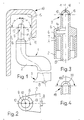
- Figures 1 to 3 shows the upper part 1 of a conventional squirt bottle made of plastic, which can be compressed manually and is used to hold and eject a liquid.
- the upper part 1 contains a bottle neck 2, which extends at right angles to a container 3.
- a hollow cylindrical plug 5 is arranged at the opening 4 of the bottle neck 2.
- the latter has an inwardly directed shoulder 6 on its outside, with which he sits on the end face 7 of the opening 4 on the bottle neck 3.
- a supply tube 8 is connected to the stopper 2 and reaches the deepest point when the wash bottle is in the use position.
- the feed tube 8 is connected to a nozzle head 9, which is cap-shaped.
- the nozzle head 9 contains a central nozzle 10 which is arranged and aligned coaxially with the axis 11 of the nozzle head 9.
- Two lateral nozzles 12 and 13 are arranged at an angle ⁇ of, for example, 90 ° to the axis 11 of the nozzle head.
- an intermediate chamber 14 can be arranged in the feed tube.
- the liquid is pressed through the feed tube 8 into the nozzle head 9 and sprays out in three different directions through the nozzles 10, 11 and 12.
- the three inner surfaces 15, 16, 17 of a hollow profile 18 which is open on one side, for example the U-profile shown, of the edge of a toilet bowl are sprayed and thus wetted uniformly.
- this intermediate chamber 14 can serve to cause an intermediate buffer in the supply tube 8, so that air can be sucked in via the additional ventilation valve during the pumping movement when the container is relieved, without the supply tube being emptied, so that when a new pressure is applied, liquid can be sprayed out immediately on the nozzle head without first having to fill the feed tube 8.
- FIG. 4 shows a modified embodiment of a nozzle head 19 with a slot nozzle 20, which has, for example, an opening angle of 180 °, so that a uniform spray curtain can be produced with such a nozzle, which can wet the inner surfaces of a hollow profile.
- the opening angle of the slot nozzle 20 can optionally also be larger or smaller than 180 °.
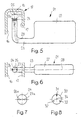
- FIGS. 5 and 6 show a further exemplary embodiment of a spray bottle 21, with a flat container 22 which has an angled bottle neck 23, at the end of which a nozzle head 24 is arranged.
- the nozzle head has two nozzles 26, 27 inclined at an angle ⁇ to the axis 25 of the nozzle head 24. The angle is selected such that the liquid jet is directed into the outer region of the upper inner surface 15 of the hollow profile 18, so that the liquid flow also receives a component of motion which drives it against the lateral inner surfaces 16, 17 of the hollow profile 18. to wet the inner surfaces of the hollow profile 18 at least approximately completely with only two nozzles.
- the nozzles 26, 27 are further arranged so that they lie in the main plane of the flat container, which is given by the main axis 28 of the container and the axis 25 of the nozzle head 24.
- the nozzle head 24 can be connected directly to the interior of the bottle neck 23 and thus the container 22. It is more expedient if the nozzle head 24 is connected to a feed tube 29 which is indicated by dash-dotted lines in FIG. 5 and which extends to the lowest point of the spray bottle 21 when it is in the operating position.
- FIG. 7 shows the nozzle head 24 with modified nozzles 26a and 27a, which are slit-shaped. This makes it possible to cover a larger area.
- FIG. 8 shows a further nozzle head 30 with nozzles 31, 32 and 33 which are arranged distributed around the circumference of the head.
- a central nozzle 31 is used for spraying a liquid jet approximately parallel to the axis 34 of the nozzle head and thus for coating, for example, the inner surface 15 of the hollow profile 18 of Figures 1 and 5.
- the side nozzles 32, 33 must be analogous to the nozzles of Figures 1 and 5 at an angle to the axis 34 of the nozzle head 30 in order to be able to spray the inner surfaces 16, 17 of the hollow profile 18 according to FIGS. 1 and 5 with a liquid.
Priority Applications (1)
| Application Number | Priority Date | Filing Date | Title |
|---|---|---|---|
| AT86810613T ATE69420T1 (de) | 1986-01-20 | 1986-12-29 | Spritzflasche. |
Applications Claiming Priority (2)
| Application Number | Priority Date | Filing Date | Title |
|---|---|---|---|
| CH19786 | 1986-01-20 | ||
| CH197/86 | 1986-01-20 |
Publications (3)
| Publication Number | Publication Date |
|---|---|
| EP0230862A2 true EP0230862A2 (fr) | 1987-08-05 |
| EP0230862A3 EP0230862A3 (en) | 1989-10-18 |
| EP0230862B1 EP0230862B1 (fr) | 1991-11-13 |
Family
ID=4181470
Family Applications (1)
| Application Number | Title | Priority Date | Filing Date |
|---|---|---|---|
| EP86810613A Expired - Lifetime EP0230862B1 (fr) | 1986-01-20 | 1986-12-29 | Fiole à jet |
Country Status (4)
| Country | Link |
|---|---|
| EP (1) | EP0230862B1 (fr) |
| AT (1) | ATE69420T1 (fr) |
| DE (1) | DE3682498D1 (fr) |
| ES (1) | ES2027640T3 (fr) |
Cited By (2)
| Publication number | Priority date | Publication date | Assignee | Title |
|---|---|---|---|---|
| DE102015111043A1 (de) * | 2015-07-08 | 2017-01-12 | Thyssenkrupp Ag | Verfahren und Vorrichtung zur Benetzung der Wandung einer Bohrung |
| EP2296820B1 (fr) * | 2008-06-18 | 2019-12-11 | Silgan Dispensing Systems Slatersville LLC | Fermeture de distribution d'une buse à faisceau |
Citations (4)
| Publication number | Priority date | Publication date | Assignee | Title |
|---|---|---|---|---|
| US2578864A (en) * | 1948-12-01 | 1951-12-18 | Earl S Tupper | Seal for flexible containers |
| FR1032143A (fr) * | 1951-02-07 | 1953-06-30 | Bouchage des flacons avec verseur diffusant les liquides | |
| US3369707A (en) * | 1966-10-14 | 1968-02-20 | Products Design And Engineerin | Dispensing cap for a container |
| CH638114A5 (de) * | 1980-07-03 | 1983-09-15 | Duering Ag | Hand-quetschflasche zur erzeugung eines gerichteten fluessigkeitsstrahles. |
-
1986
- 1986-12-29 AT AT86810613T patent/ATE69420T1/de not_active IP Right Cessation
- 1986-12-29 DE DE8686810613T patent/DE3682498D1/de not_active Expired - Lifetime
- 1986-12-29 ES ES198686810613T patent/ES2027640T3/es not_active Expired - Lifetime
- 1986-12-29 EP EP86810613A patent/EP0230862B1/fr not_active Expired - Lifetime
Patent Citations (4)
| Publication number | Priority date | Publication date | Assignee | Title |
|---|---|---|---|---|
| US2578864A (en) * | 1948-12-01 | 1951-12-18 | Earl S Tupper | Seal for flexible containers |
| FR1032143A (fr) * | 1951-02-07 | 1953-06-30 | Bouchage des flacons avec verseur diffusant les liquides | |
| US3369707A (en) * | 1966-10-14 | 1968-02-20 | Products Design And Engineerin | Dispensing cap for a container |
| CH638114A5 (de) * | 1980-07-03 | 1983-09-15 | Duering Ag | Hand-quetschflasche zur erzeugung eines gerichteten fluessigkeitsstrahles. |
Cited By (2)
| Publication number | Priority date | Publication date | Assignee | Title |
|---|---|---|---|---|
| EP2296820B1 (fr) * | 2008-06-18 | 2019-12-11 | Silgan Dispensing Systems Slatersville LLC | Fermeture de distribution d'une buse à faisceau |
| DE102015111043A1 (de) * | 2015-07-08 | 2017-01-12 | Thyssenkrupp Ag | Verfahren und Vorrichtung zur Benetzung der Wandung einer Bohrung |
Also Published As
| Publication number | Publication date |
|---|---|
| EP0230862B1 (fr) | 1991-11-13 |
| ES2027640T3 (es) | 1992-06-16 |
| EP0230862A3 (en) | 1989-10-18 |
| ATE69420T1 (de) | 1991-11-15 |
| DE3682498D1 (de) | 1991-12-19 |
Similar Documents
| Publication | Publication Date | Title |
|---|---|---|
| DE3121591C2 (de) | Hand-Quetschflasche, insbesondere zur Reinigung von WC-Schüsseln | |
| DE2265393C3 (de) | Flüssigkeitssprühvorrichtung | |
| DE2852946A1 (de) | Abzapfgeraet fuer das abzapfen kohlensaeurehaltiger getraenke aus mit einem einverleibten kohlensaeurevorratsbehaelter versehenen fluessigkeitsbehaeltern | |
| DE2610129A1 (de) | Schaumerzeuger | |
| DE7024995U (de) | Geschirr spulmaschine | |
| DE2612471A1 (de) | Dosierspruehvorrichtung | |
| DE7221340U (de) | Geraet zum enthaerten kleiner mengen von wasser | |
| DE2512803C3 (de) | Zerstäuberkopf | |
| EP0230862B1 (fr) | Fiole à jet | |
| DE1475167A1 (de) | Spruehkopf fuer elastische Kunststoff-Flaschen | |
| EP1747771B1 (fr) | Douche nasale | |
| DE3410305C1 (de) | Membranpumpe | |
| DE837298C (de) | Selbsttaetiger Verschluss fuer Behaelter, die gleichzeitig als Giesser, Verteiler, Dosierer oder Zerstaeuber dienen | |
| DE946595C (de) | Trichter fuer Schankzwecke od. dgl. | |
| DE2648288A1 (de) | Zerstaeuber | |
| DE7802067U1 (de) | Vorrichtung zum Ausdruecken von Tubenpaste | |
| DE2348974A1 (de) | Spruehvorrichtung fuer fluessige, insbesondere biotechnische spruehmittel | |
| AT159875B (de) | Verfahren und Vorrichtung zum Beschicken von mit Druckluft betriebenen Malgeräten. | |
| DE808878C (de) | Zerstaeuber | |
| DE19710871C2 (de) | Vorrichtung zum Auftragen von Flüssigkeiten | |
| DE3731464A1 (de) | In eine spritzpistole einsetzbarer behaelter | |
| EP0278947A2 (fr) | Système de contribution de mousse sans pression gazeuse | |
| DE4242460A1 (de) | Farbroller | |
| EP0131838A2 (fr) | Applicateur pour application ou projection sélective de préparations cosmétiques fluides | |
| DE1806996U (de) | Spruehvorrichtung. |
Legal Events
| Date | Code | Title | Description |
|---|---|---|---|
| PUAI | Public reference made under article 153(3) epc to a published international application that has entered the european phase |
Free format text: ORIGINAL CODE: 0009012 |
|
| AK | Designated contracting states |
Kind code of ref document: A2 Designated state(s): AT BE CH DE ES FR GB IT LI LU NL SE |
|
| PUAL | Search report despatched |
Free format text: ORIGINAL CODE: 0009013 |
|
| AK | Designated contracting states |
Kind code of ref document: A3 Designated state(s): AT BE CH DE ES FR GB IT LI LU NL SE |
|
| RHK1 | Main classification (correction) |
Ipc: B65D 1/32 |
|
| 17P | Request for examination filed |
Effective date: 19900321 |
|
| 17Q | First examination report despatched |
Effective date: 19900813 |
|
| GRAA | (expected) grant |
Free format text: ORIGINAL CODE: 0009210 |
|
| AK | Designated contracting states |
Kind code of ref document: B1 Designated state(s): AT BE CH DE ES FR GB IT LI LU NL SE |
|
| REF | Corresponds to: |
Ref document number: 69420 Country of ref document: AT Date of ref document: 19911115 Kind code of ref document: T |
|
| REF | Corresponds to: |
Ref document number: 3682498 Country of ref document: DE Date of ref document: 19911219 |
|
| ET | Fr: translation filed | ||
| ITF | It: translation for a ep patent filed |
Owner name: STUDIO JAUMANN |
|
| GBT | Gb: translation of ep patent filed (gb section 77(6)(a)/1977) | ||
| REG | Reference to a national code |
Ref country code: ES Ref legal event code: FG2A Ref document number: 2027640 Country of ref document: ES Kind code of ref document: T3 |
|
| PLBE | No opposition filed within time limit |
Free format text: ORIGINAL CODE: 0009261 |
|
| STAA | Information on the status of an ep patent application or granted ep patent |
Free format text: STATUS: NO OPPOSITION FILED WITHIN TIME LIMIT |
|
| 26N | No opposition filed | ||
| PGFP | Annual fee paid to national office [announced via postgrant information from national office to epo] |
Ref country code: AT Payment date: 19921214 Year of fee payment: 7 |
|
| PGFP | Annual fee paid to national office [announced via postgrant information from national office to epo] |
Ref country code: LU Payment date: 19921215 Year of fee payment: 7 |
|
| EPTA | Lu: last paid annual fee | ||
| PG25 | Lapsed in a contracting state [announced via postgrant information from national office to epo] |
Ref country code: LU Free format text: LAPSE BECAUSE OF NON-PAYMENT OF DUE FEES Effective date: 19931229 Ref country code: AT Effective date: 19931229 |
|
| PGFP | Annual fee paid to national office [announced via postgrant information from national office to epo] |
Ref country code: GB Payment date: 19941222 Year of fee payment: 9 |
|
| PGFP | Annual fee paid to national office [announced via postgrant information from national office to epo] |
Ref country code: FR Payment date: 19941226 Year of fee payment: 9 |
|
| PGFP | Annual fee paid to national office [announced via postgrant information from national office to epo] |
Ref country code: DE Payment date: 19941227 Year of fee payment: 9 |
|
| PGFP | Annual fee paid to national office [announced via postgrant information from national office to epo] |
Ref country code: SE Payment date: 19941229 Year of fee payment: 9 |
|
| PGFP | Annual fee paid to national office [announced via postgrant information from national office to epo] |
Ref country code: ES Payment date: 19941230 Year of fee payment: 9 |
|
| PGFP | Annual fee paid to national office [announced via postgrant information from national office to epo] |
Ref country code: NL Payment date: 19941231 Year of fee payment: 9 |
|
| PGFP | Annual fee paid to national office [announced via postgrant information from national office to epo] |
Ref country code: BE Payment date: 19950118 Year of fee payment: 9 |
|
| EAL | Se: european patent in force in sweden |
Ref document number: 86810613.9 |
|
| PGFP | Annual fee paid to national office [announced via postgrant information from national office to epo] |
Ref country code: CH Payment date: 19950328 Year of fee payment: 9 |
|
| PG25 | Lapsed in a contracting state [announced via postgrant information from national office to epo] |
Ref country code: GB Effective date: 19951229 |
|
| PG25 | Lapsed in a contracting state [announced via postgrant information from national office to epo] |
Ref country code: SE Effective date: 19951230 Ref country code: ES Free format text: LAPSE BECAUSE OF NON-PAYMENT OF DUE FEES Effective date: 19951230 |
|
| PG25 | Lapsed in a contracting state [announced via postgrant information from national office to epo] |
Ref country code: LI Effective date: 19951231 Ref country code: CH Effective date: 19951231 Ref country code: BE Effective date: 19951231 |
|
| BERE | Be: lapsed |
Owner name: GRANZOTTO ARTEMIO Effective date: 19951231 |
|
| PG25 | Lapsed in a contracting state [announced via postgrant information from national office to epo] |
Ref country code: NL Effective date: 19960701 |
|
| REG | Reference to a national code |
Ref country code: CH Ref legal event code: PL |
|
| GBPC | Gb: european patent ceased through non-payment of renewal fee |
Effective date: 19951229 |
|
| PG25 | Lapsed in a contracting state [announced via postgrant information from national office to epo] |
Ref country code: FR Effective date: 19960830 |
|
| NLV4 | Nl: lapsed or anulled due to non-payment of the annual fee |
Effective date: 19960701 |
|
| PG25 | Lapsed in a contracting state [announced via postgrant information from national office to epo] |
Ref country code: DE Effective date: 19960903 |
|
| REG | Reference to a national code |
Ref country code: FR Ref legal event code: ST |
|
| REG | Reference to a national code |
Ref country code: ES Ref legal event code: FD2A Effective date: 20010503 |
|
| PG25 | Lapsed in a contracting state [announced via postgrant information from national office to epo] |
Ref country code: IT Free format text: LAPSE BECAUSE OF NON-PAYMENT OF DUE FEES Effective date: 20051229 |