EP0230862A2 - Washing bottle - Google Patents
Washing bottle Download PDFInfo
- Publication number
- EP0230862A2 EP0230862A2 EP86810613A EP86810613A EP0230862A2 EP 0230862 A2 EP0230862 A2 EP 0230862A2 EP 86810613 A EP86810613 A EP 86810613A EP 86810613 A EP86810613 A EP 86810613A EP 0230862 A2 EP0230862 A2 EP 0230862A2
- Authority
- EP
- European Patent Office
- Prior art keywords
- nozzle head
- nozzle
- bottle according
- nozzles
- spray bottle
- Prior art date
- Legal status (The legal status is an assumption and is not a legal conclusion. Google has not performed a legal analysis and makes no representation as to the accuracy of the status listed.)
- Granted
Links
Images
Classifications
-
- B—PERFORMING OPERATIONS; TRANSPORTING
- B65—CONVEYING; PACKING; STORING; HANDLING THIN OR FILAMENTARY MATERIAL
- B65D—CONTAINERS FOR STORAGE OR TRANSPORT OF ARTICLES OR MATERIALS, e.g. BAGS, BARRELS, BOTTLES, BOXES, CANS, CARTONS, CRATES, DRUMS, JARS, TANKS, HOPPERS, FORWARDING CONTAINERS; ACCESSORIES, CLOSURES, OR FITTINGS THEREFOR; PACKAGING ELEMENTS; PACKAGES
- B65D47/00—Closures with filling and discharging, or with discharging, devices
- B65D47/04—Closures with discharging devices other than pumps
- B65D47/06—Closures with discharging devices other than pumps with pouring spouts or tubes; with discharge nozzles or passages
Definitions
- the invention relates to a squirt bottle according to the preamble of claim 1.
- Wash bottles of the type mentioned at the outset are known several times, for example from CH-PS 638 114.
- a hollow plug which has a spray tube which leads outside and communicates with a feed tube leading into the interior of the bottle.
- the liquid is only sprayed in one direction in a jet.
- the bottle In the case of a structure with a U-shaped structural part, the bottle has to be moved back and forth several times and the position thereof has to be changed in order to accommodate the offset surfaces of depressions to be sprayed simultaneously by repeated squeezing. Uniform spraying is normally impossible, and the necessary back and forth movements and changes in position of the bottle when moving are time-consuming and cumbersome.
- the invention has for its object to design a squirt bottle of the type mentioned in such a way that the uniform spraying of several mutually offset surfaces of a hollow profile that is open on one side, such as the edge of a toilet bowl, can be carried out in a single operation, thus reducing the time required for this purpose and reduce the fluid consumption thanks to even spraying.
- this object is achieved by the features defined in the characterizing part of claim 1.
- a squeeze bottle it is possible to wet a hollow profile, for example a U-profile, which is open on one side, at least for the most part, preferably completely, with a liquid in a single operation, which not only reduces the working time for such wetting, but also a safe one Wetting of at least the largest part of the inner surface of the hollow profile is reliably achieved, in which case the outlay on liquid is also reduced, since repeated, non-targeted spraying of the surfaces is eliminated.
- a slot nozzle or two nozzle openings arranged at an angle can suffice to allow the hollow profile, which is open on one side, to be sprayed out.
- it is advantageous to provide a further central nozzle so that, for example in the case of a U-shaped hollow profile, a separate nozzle is assigned to each side of the profile.
- training according to claim 3 is advantageous.
- the nozzles can be arranged distributed on a nozzle head, it is essential that they are effective in different directions, so that each nozzle can spray a different inner surface of a hollow profile.
- an embodiment according to claim 4 is advantageous, since then there is a specific association between nozzles and containers, so that when using the position of the container, the user can simultaneously determine in which direction the spraying of the hollow profile will take place.
- a nozzle head can be designed flat and contain nozzles arranged in a correspondingly inclined manner. It is more advantageous if the nozzle head is designed like a cap, so that a spherical arrangement of the nozzles is possible.
- nozzle head it may be sufficient to arrange the nozzle head directly on the neck of the container. If, however, the nozzle head is not located close to or directly at the lowest point in the operating position of the squirt bottle, an embodiment according to claim 9 is recommended.
- the wash bottle is particularly suitable for spraying a cleaning and / or disinfecting liquid into the U-shaped edge of a toilet bowl.
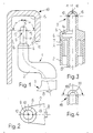
- Figures 1 to 3 shows the upper part 1 of a conventional squirt bottle made of plastic, which can be compressed manually and is used to hold and eject a liquid.
- the upper part 1 contains a bottle neck 2, which extends at right angles to a container 3.
- a hollow cylindrical plug 5 is arranged at the opening 4 of the bottle neck 2.
- the latter has an inwardly directed shoulder 6 on its outside, with which he sits on the end face 7 of the opening 4 on the bottle neck 3.
- a supply tube 8 is connected to the stopper 2 and reaches the deepest point when the wash bottle is in the use position.
- the feed tube 8 is connected to a nozzle head 9, which is cap-shaped.
- the nozzle head 9 contains a central nozzle 10 which is arranged and aligned coaxially with the axis 11 of the nozzle head 9.
- Two lateral nozzles 12 and 13 are arranged at an angle ⁇ of, for example, 90 ° to the axis 11 of the nozzle head.
- an intermediate chamber 14 can be arranged in the feed tube.
- the liquid is pressed through the feed tube 8 into the nozzle head 9 and sprays out in three different directions through the nozzles 10, 11 and 12.
- the three inner surfaces 15, 16, 17 of a hollow profile 18 which is open on one side, for example the U-profile shown, of the edge of a toilet bowl are sprayed and thus wetted uniformly.
- this intermediate chamber 14 can serve to cause an intermediate buffer in the supply tube 8, so that air can be sucked in via the additional ventilation valve during the pumping movement when the container is relieved, without the supply tube being emptied, so that when a new pressure is applied, liquid can be sprayed out immediately on the nozzle head without first having to fill the feed tube 8.
- FIG. 4 shows a modified embodiment of a nozzle head 19 with a slot nozzle 20, which has, for example, an opening angle of 180 °, so that a uniform spray curtain can be produced with such a nozzle, which can wet the inner surfaces of a hollow profile.
- the opening angle of the slot nozzle 20 can optionally also be larger or smaller than 180 °.
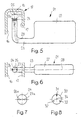
- FIGS. 5 and 6 show a further exemplary embodiment of a spray bottle 21, with a flat container 22 which has an angled bottle neck 23, at the end of which a nozzle head 24 is arranged.
- the nozzle head has two nozzles 26, 27 inclined at an angle ⁇ to the axis 25 of the nozzle head 24. The angle is selected such that the liquid jet is directed into the outer region of the upper inner surface 15 of the hollow profile 18, so that the liquid flow also receives a component of motion which drives it against the lateral inner surfaces 16, 17 of the hollow profile 18. to wet the inner surfaces of the hollow profile 18 at least approximately completely with only two nozzles.
- the nozzles 26, 27 are further arranged so that they lie in the main plane of the flat container, which is given by the main axis 28 of the container and the axis 25 of the nozzle head 24.
- the nozzle head 24 can be connected directly to the interior of the bottle neck 23 and thus the container 22. It is more expedient if the nozzle head 24 is connected to a feed tube 29 which is indicated by dash-dotted lines in FIG. 5 and which extends to the lowest point of the spray bottle 21 when it is in the operating position.
- FIG. 7 shows the nozzle head 24 with modified nozzles 26a and 27a, which are slit-shaped. This makes it possible to cover a larger area.
- FIG. 8 shows a further nozzle head 30 with nozzles 31, 32 and 33 which are arranged distributed around the circumference of the head.
- a central nozzle 31 is used for spraying a liquid jet approximately parallel to the axis 34 of the nozzle head and thus for coating, for example, the inner surface 15 of the hollow profile 18 of Figures 1 and 5.
- the side nozzles 32, 33 must be analogous to the nozzles of Figures 1 and 5 at an angle to the axis 34 of the nozzle head 30 in order to be able to spray the inner surfaces 16, 17 of the hollow profile 18 according to FIGS. 1 and 5 with a liquid.
Abstract
Description
Die Erfindung betrifft eine Spritzflasche gemäss Oberbegriff des Anspruches 1.The invention relates to a squirt bottle according to the preamble of
Spritzflaschen der eingangs genannten Art sind mehrfach bekannt, so beispielsweise aus der CH-PS 638 114. In deren Flaschenhals steckt ein hohler Pfropfen, welcher ein Spritzröhrchen besitzt, welches ins Freie führt und mit einem ins Flascheninnere führenden Zuleitröhrchen kommuniziert. Die Flüssigkeit wird bei raschem Zusammendrücken der Flasche mittels einer Düse nur in einer Richtung in einem Strahl ausgespritzt Bei einem Baukörper mit einem U-förmigen Strukturteil muss die Flasche mehrfach hin- sowie herbewegt und die Stellung derselben verändert werden, um die zueinander versetzten Flächen von Vertiefungen gleichzeitig durch wiederholtes Zusammendrücken zu bespritzen. Eine gleichmässige Bespritzung ist normalerweise unmöglich, überdies sind die erforderlichen Hin- und Herbewegungen und Stellungsveränderungen der Flasche beim Bewegen zeitraubend und umständlich.Wash bottles of the type mentioned at the outset are known several times, for example from CH-PS 638 114. In the bottle neck there is a hollow plug which has a spray tube which leads outside and communicates with a feed tube leading into the interior of the bottle. When the bottle is quickly compressed using a nozzle, the liquid is only sprayed in one direction in a jet. In the case of a structure with a U-shaped structural part, the bottle has to be moved back and forth several times and the position thereof has to be changed in order to accommodate the offset surfaces of depressions to be sprayed simultaneously by repeated squeezing. Uniform spraying is normally impossible, and the necessary back and forth movements and changes in position of the bottle when moving are time-consuming and cumbersome.
Der Erfindung liegt die Aufgabe zugrunde, eine Spritzflasche der eingangs genannten Art so auszubilden, dass die gleichmässige Bespritzung mehrerer zueinander versetzter Flächen enes einseitig offenen Hohlprofils, wie den Rand einer Klosettschüssel, in einem einzigen Arbeitsgang auszuführen, und damit den hierzu benötigten Zeitbedarf zu verkürzen sowie den Flüssigkeitsaufwand dank gleichmässiger Bespritzung zu reduzieren.The invention has for its object to design a squirt bottle of the type mentioned in such a way that the uniform spraying of several mutually offset surfaces of a hollow profile that is open on one side, such as the edge of a toilet bowl, can be carried out in a single operation, thus reducing the time required for this purpose and reduce the fluid consumption thanks to even spraying.
Erfindungsgemäss wird diese Aufgabe durch die im Kennzeichen des Anspruches 1 definierten Merkmale gelöst. Mit einer solchen Spritzflasche ist es möglich, ein einseitig offenes Hohlprofil, beispielsweise ein U-Profil, in einem einzigen Arbeitsgang mindestens grösstenteils, vorzugsweise vollständig mit einer Flüssigkeit zu benetzen, wodurch nicht nur die Arbeitszeit für ein solches Benetzen reduziert wird, sondern auch ein sicheres Benetzen mindestens des grössten Teils der Innenfläche des Hohlprofils sicher erreicht wird, wobei dann überdies der Aufwand an Flüssigkeit reduziert wird, da ein mehrmaliges ungezieltes Bespritzen der Flächen entfällt.According to the invention, this object is achieved by the features defined in the characterizing part of
Vorteilhafte Ausgestaltungen der Spritzflasche sind in den Ansprüchen 2 bis 10 beschrieben.Advantageous embodiments of the squirt bottle are described in
Es können eine Schlitzdüse oder zwei unter einem Winkel angeordnete Düsenöffnungen genügen, um ein Ausspritzen des einseitig offenen Hohlprofils zu ermöglichen. Insbesondere bei Verwendung normaler Düsenöffnungen ist es jedoch vorteilhaft gemäss Anspruch 2 eine weitere zentrale Düse vorzusehen, sodass beispielsweise bei einem U-förmigen Hohlprofil jeder Seite des Profils eine eigene Düse zugeordnet ist. Insbesondere in diesem Falle ist eine Ausbildung nach Anspruch 3 von Vorteil. Die Düsen können verteilt an einem Düsenkopf angeordnet sein, wesentlich ist, dass sie in verschiedenen Richtungen wirksam sind, sodass jede Düse eine andere Innenfläche eines Hohlprofils bespritzen kann. Vorteilhaft ist jedoch eine Ausgestaltung nach Anspruch 4, da dann eine bestimmte Zuordnung zwischen Düsen und Behältern gegeben ist, sodass bei der Benützung anhand der Lage des Behälters der Benützer auch gleichzeitig feststellen kann in welcher Richtung das Bespritzen des Hohlprofils erfolgen wird.A slot nozzle or two nozzle openings arranged at an angle can suffice to allow the hollow profile, which is open on one side, to be sprayed out. In particular when using normal nozzle openings, however, it is advantageous to provide a further central nozzle, so that, for example in the case of a U-shaped hollow profile, a separate nozzle is assigned to each side of the profile. In this case in particular, training according to claim 3 is advantageous. The nozzles can be arranged distributed on a nozzle head, it is essential that they are effective in different directions, so that each nozzle can spray a different inner surface of a hollow profile. However, an embodiment according to claim 4 is advantageous, since then there is a specific association between nozzles and containers, so that when using the position of the container, the user can simultaneously determine in which direction the spraying of the hollow profile will take place.
Für die Ausbildung des Spritzkopfes bestehen verschiedene Möglichkeiten. Neben Düsenöffnungen mit kreisrundem Querschnitt können beispielsweise auch solche gemäss Anspruch 5 vorgesehen sein. Auch eine Schlitzdüse gemäss Anspruch 6 ist möglich. Ein Düsenkopf kann flach ausgestaltet sein und entsprechend geneigt angeordnete Düsen enthalten. Vorteilhafter ist es, wenn der Düsenkopf gemäss Anspruch 7 kappenartig ausgebildet ist, sodass eine sphärische Anordnung der Düsen möglich ist.There are various options for the formation of the spray head. In addition to nozzle openings with a circular cross section, those according to
Es kann ausreichend sein, den Düsenkopf gemäss Anspruch 8 direkt am Hals des Behälters anzuordnen. Wenn jedoch der Düsenkopf in Betriebsstellung der Spritzflasche nicht nahe oder direkt am tiefsten Ort angeordnet ist, empfiehlt sich eine Ausgestaltung nach Anspruch 9. Gegebenenfalls kann es zweckmässig sein, eine Zwischenkammer gemäss Anspruch 10 vorzusehen.It may be sufficient to arrange the nozzle head directly on the neck of the container. If, however, the nozzle head is not located close to or directly at the lowest point in the operating position of the squirt bottle, an embodiment according to
Die Spritzflasche ist besonders geeignet zum Ausspritzen einer Reinigungs- und/oder Desinfektionsflüssigkeit in den U-förmigen Rand einer Klosettschüssel.The wash bottle is particularly suitable for spraying a cleaning and / or disinfecting liquid into the U-shaped edge of a toilet bowl.
Ausführungsbeispiele der Erfindung werden nachfolgend anhand der Zeichnungen näher erläutert, dabei zeigen:
Figur 1 die Anordnung eines Flaschenhalses mit Spritzdüse in einem nach unten offenen Hohlprofil, in Seitenansicht;Figur 2 den Flaschenhals mit Düsenkopf in Draufsicht und in grösserem Massstab;- Figur 3 den Düsenkopf am Flaschenhals im Längsschnitt und in grösserem Massstab;
- Figur 4 eine Schlitzdüse eines Düsenkopfes im Längsschnitt;
Figur 5 eine weitere Spritzflasche an einem nach unten offenen Hohlprofil, in Seitenansicht und teilweise geschnitten;Figur 6 die Spritzflasche derFigur 5 in DraufsichtFigur 7 einen Düsenkopf mit schlitzförmigen Düsen, in Draufsicht;
undFigur 8 einen Düsenkopf mit einer weiteren Anordnung von Düsen in Draufsicht.
- Figure 1 shows the arrangement of a bottle neck with spray nozzle in a hollow profile open at the bottom, in side view;
- Figure 2 shows the bottle neck with nozzle head in plan view and on a larger scale;
- Figure 3 shows the nozzle head on the bottle neck in longitudinal section and on a larger scale;
- Figure 4 shows a slot nozzle of a nozzle head in longitudinal section;
- 5 shows a further squirt bottle on a hollow profile open at the bottom, in a side view and partially cut;
- Figure 6 shows the squirt bottle of Figure 5 in plan view
- Figure 7 shows a nozzle head with slot-shaped nozzles, in plan view;
and - Figure 8 shows a nozzle head with a further arrangement of nozzles in plan view.
Die Figuren 1 bis 3 zeigt den Oberteil 1 einer konventionellen Spritzflasche aus Kunststoff, die manuell zusammendrückbar ist und zur Aufnahme und zum Ausspritzen einer Flüssigkeit dient. Der Oberteil 1 enthält einen Flaschenhals 2, der in rechtwinkligen Krümmungen zu einem Behälter 3 verläuft. An der Oeffnung 4 des Flaschenhalses 2 ist ein hohlzylindrischer Pfropfen 5 angeordnet. Letzterer weist an seiner Aussenseite einen einwärts gerichteten Absatz 6 auf, mit welchem er an der Stirnseite 7 der Oeffnung 4 am Flaschenhals 3 aufsitzt. Am Pfropfen 2 ist ein Zuleitungsröhrchen 8 angeschlossen, das bei in Gebrauchsstellung befindlicher Spritzflasche bis an deren tiefsten Punkt erreicht. Das Zuleitungsröhrchen 8 steht mit einem Düsenkopf 9 in Verbindung, der kappenartig ausgebildet ist. Der Düsenkopf 9 enthält eine zentrale Düse 10, die koaxial mit der Achse 11 des Düsenkopfes 9 angeordnet und ausgerichtet ist. Zwei seitliche Düsen 12 und 13 sind in einem Winkel α von beispielsweise 90° zur Achse 11 des Düsenkopfes angeordnet. Im Zuleitungsröhrchen kann, wie auf der linken Seite der Figur 3 angedeutet, eine Zwischenkammer 14 angeordnet sein.Figures 1 to 3 shows the
Die Flüssigkeit wird, beim Zusammendrücken des Behälters 3 durch den entstehenden Innendruck durch das Zuleitungsröhrchen 8 in den Düsenkopf 9 gepresst und spritzt in drei verschiedenen Richtungen durch die Düsen 10, 11 und 12 aus. Dabei werden die drei Innenflächen 15, 16, 17 eines einseitig offenen Hohlprofils 18, beispielsweise des gezeigten U-Profils des Randes einer Klosettschüssel bespritzt und damit gleichmäsig benetzt.When the container 3 is compressed by the resulting internal pressure, the liquid is pressed through the
Bei Verwendung der Zwischenkammer 14 erfolgt das Ausspritzen der Flüssigkeit beim Zusammendrücken der Spritzflasche nicht sofort und schlagartig, da die Zwischenkammer 14 erst gefüllt werden muss, bevor die Flüssigkeit in den Düsenkopf 9 gelangt und aus den Düsen 10, 11 und 12 austreten kann. Dadurch wird eine sparsamere Verwendung der Flüssigkeit ermöglicht. Diese Zwischenkammer 14 kann, in Verbindung mit einem zusätzlichen, nicht dargestellten Belüftungsventil dazu dienen, einen Zwischenpuffer im Zuleitungsröhrchen 8 zu bewirken, sodass bei der Pumpbewegung beim Entlasten des Behälters Luft über das zusätzliche Belüftungsventil angesaugt werden kann, ohne dass sich das Zuleitungsröhrchen entleert, sodass beim Anlegen eines neuen Druckes sofort Flüssigkeit am Düsenkopf ausgespritzt werden kann, ohne dass das Zuleitungsröhrchen 8 erst gefüllt werden muss.When using the
Die Figur 4 zeigt eine abgewandelte Ausführung eines Düsenkopfes 19 mit einer Schlitzdüse 20, die beispielsweise einen Oeffnungwinkel von 180° aufweist, sodass mit einer solchen Düse ein gleichmässiger Spritzvorhang erzeugt werden kann, der die Innenflächen eines Hohlprofils benetzen kann. Der Oeffnungswinkel der Schlitzdüse 20 kann gegebenenfalls auch grösser oder kleiner als 180° sein.FIG. 4 shows a modified embodiment of a
Die Figuren 5 und 6 zeigen ein weiteres Ausführungsbeispiel einer Spritzflasche 21, mit einem flachen Behälter 22 der einen abgewinkelten Flaschenhals 23 aufweist, an dessen Ende ein Düsenkopf 24 angeordnet ist. Der Düsenkopf weist zwei unter einem Winkel α zur Achse 25 des Düsenkopfes 24 geneigte Düsen 26, 27 auf. Der Winkel ist so gewählt, dass der Flüssigkeitsstrahl in den äusseren Bereich der oberen Innenfläche 15 des Hohlprofils 18 gerichtet ist, sodass der Flüssigkeitsstrom auch eine Bewegungskomponente erhält, die ihn gegen die seitlichen Innenflächen 16, 17 des Hohlprofiles 18 treibt, damit ist es möglich, mit nur zwei Düsen die Innenflächen des Hohlprofils 18 mindestens annähernd vollständig zu benetzen. Die Düsen 26, 27 sind ferner so angeordnet, dass sie in der Hauptebene des flachen Behälters liegen, die durch die Hauptachse 28 des Behälters und die Achse 25 des Düsenkopfes 24 gegeben ist. Der Düsenkopf 24 kann direkt mit dem Inneren des Flaschenhalses 23 und damit des Behälters 22 in Verbindung stehen. Zweckmässiger ist es, wenn der Düsenkopf 24 mit einem Zuleitungsröhrchen 29 in Verbindung steht, das in Figur 5 strichpunktiert angedeutet ist und das an die tiefste Stelle der Spritzflasche 21 reicht, wenn diese sich in Betriebsstellung befindet.FIGS. 5 and 6 show a further exemplary embodiment of a
Die Figur 7 zeigt den Düsenkopf 24 mit abgewandelten Düsen 26a und 27a, die schlitzförmig ausgebildet sind. Dadurch ist die Bestreichung eines grösseren Flächenbereiches möglich.FIG. 7 shows the
Figur 8 zeigt einen weiteren Düsenkopf 30 mit Düsen 31, 32 und 33, die am Umfang des Kopfes verteilt angeordnet sind. Eine zentrale Düse 31 dient dabei zum Ausspritzen eines Flüssigkeitsstrahles annähernd parallel zur Aches 34 des Düsenkopfes und damit zur Bestreichung beispielsweise der Innen fläche 15 des Hohlprofils 18 der Figuren 1 bzw. 5. Die seitlichen Düsen 32, 33 müssen analog den Düsen der Figuren 1 und 5 unter einem Winkel zur Achse 34 des Düsenkopfes 30 angeordnet sein, um die Innenflächen 16, 17 des Hohlprofiles 18 gemäss den Figuren 1 bzw. 5 mit einer Flüssigkeit bespritzen zu können.FIG. 8 shows a
Es sind noch zahlreiche weitere Ausführungsbeispiele denkbar, insbesondere sind auch einzelne Merkmale der gezeigten Ausführungsbeispiele untereinander austauschbar.Numerous further exemplary embodiments are also conceivable, in particular individual features of the exemplary embodiments shown are also interchangeable.
Claims (10)
Priority Applications (1)
| Application Number | Priority Date | Filing Date | Title |
|---|---|---|---|
| AT86810613T ATE69420T1 (en) | 1986-01-20 | 1986-12-29 | SQUID BOTTLE. |
Applications Claiming Priority (2)
| Application Number | Priority Date | Filing Date | Title |
|---|---|---|---|
| CH19786 | 1986-01-20 | ||
| CH197/86 | 1986-01-20 |
Publications (3)
| Publication Number | Publication Date |
|---|---|
| EP0230862A2 true EP0230862A2 (en) | 1987-08-05 |
| EP0230862A3 EP0230862A3 (en) | 1989-10-18 |
| EP0230862B1 EP0230862B1 (en) | 1991-11-13 |
Family
ID=4181470
Family Applications (1)
| Application Number | Title | Priority Date | Filing Date |
|---|---|---|---|
| EP86810613A Expired - Lifetime EP0230862B1 (en) | 1986-01-20 | 1986-12-29 | Washing bottle |
Country Status (4)
| Country | Link |
|---|---|
| EP (1) | EP0230862B1 (en) |
| AT (1) | ATE69420T1 (en) |
| DE (1) | DE3682498D1 (en) |
| ES (1) | ES2027640T3 (en) |
Cited By (2)
| Publication number | Priority date | Publication date | Assignee | Title |
|---|---|---|---|---|
| DE102015111043A1 (en) * | 2015-07-08 | 2017-01-12 | Thyssenkrupp Ag | Method and device for wetting the wall of a bore |
| EP2296820B1 (en) * | 2008-06-18 | 2019-12-11 | Silgan Dispensing Systems Slatersville LLC | Dispensing closure for a fan spray nozzle |
Citations (4)
| Publication number | Priority date | Publication date | Assignee | Title |
|---|---|---|---|---|
| US2578864A (en) * | 1948-12-01 | 1951-12-18 | Earl S Tupper | Seal for flexible containers |
| FR1032143A (en) * | 1951-02-07 | 1953-06-30 | Capping of bottles with pourer diffusing liquids | |
| US3369707A (en) * | 1966-10-14 | 1968-02-20 | Products Design And Engineerin | Dispensing cap for a container |
| CH638114A5 (en) * | 1980-07-03 | 1983-09-15 | Duering Ag | HAND CRUSH BOTTLE FOR GENERATING A DIRECTED JET OF LIQUID. |
-
1986
- 1986-12-29 DE DE8686810613T patent/DE3682498D1/en not_active Expired - Lifetime
- 1986-12-29 EP EP86810613A patent/EP0230862B1/en not_active Expired - Lifetime
- 1986-12-29 ES ES198686810613T patent/ES2027640T3/en not_active Expired - Lifetime
- 1986-12-29 AT AT86810613T patent/ATE69420T1/en not_active IP Right Cessation
Patent Citations (4)
| Publication number | Priority date | Publication date | Assignee | Title |
|---|---|---|---|---|
| US2578864A (en) * | 1948-12-01 | 1951-12-18 | Earl S Tupper | Seal for flexible containers |
| FR1032143A (en) * | 1951-02-07 | 1953-06-30 | Capping of bottles with pourer diffusing liquids | |
| US3369707A (en) * | 1966-10-14 | 1968-02-20 | Products Design And Engineerin | Dispensing cap for a container |
| CH638114A5 (en) * | 1980-07-03 | 1983-09-15 | Duering Ag | HAND CRUSH BOTTLE FOR GENERATING A DIRECTED JET OF LIQUID. |
Cited By (2)
| Publication number | Priority date | Publication date | Assignee | Title |
|---|---|---|---|---|
| EP2296820B1 (en) * | 2008-06-18 | 2019-12-11 | Silgan Dispensing Systems Slatersville LLC | Dispensing closure for a fan spray nozzle |
| DE102015111043A1 (en) * | 2015-07-08 | 2017-01-12 | Thyssenkrupp Ag | Method and device for wetting the wall of a bore |
Also Published As
| Publication number | Publication date |
|---|---|
| ATE69420T1 (en) | 1991-11-15 |
| ES2027640T3 (en) | 1992-06-16 |
| DE3682498D1 (en) | 1991-12-19 |
| EP0230862B1 (en) | 1991-11-13 |
| EP0230862A3 (en) | 1989-10-18 |
Similar Documents
| Publication | Publication Date | Title |
|---|---|---|
| DE3121591C2 (en) | Hand squeeze bottle, especially for cleaning toilet bowls | |
| DE2731980C2 (en) | Device for dispensing liquid or pasty products | |
| DE2265392C3 (en) | Liquid spray device | |
| DE2852946A1 (en) | DISPENSER FOR TAPPING CARBON BEVERAGES FROM LIQUID CONTAINERS WITH AN INCORPORATED CARBON RESERVOIR | |
| DE2610129A1 (en) | FOAM GENERATOR | |
| DE7024995U (en) | Dishwasher | |
| DE2612471A1 (en) | DOSING SPRAY DEVICE | |
| DE7221340U (en) | DEVICE FOR SOFTENING SMALL AMOUNTS OF WATER | |
| DE2512803C3 (en) | Atomizer head | |
| EP0230862B1 (en) | Washing bottle | |
| DE1475167A1 (en) | Spray head for elastic plastic bottles | |
| DE3410305C1 (en) | Diaphragm pump | |
| DE837298C (en) | Automatic closure for containers that also serve as pourers, distributors, dispensers or nebulizers | |
| DE946595C (en) | Funnel for dispensing purposes or the like. | |
| DE2648288A1 (en) | SPRAYER | |
| DE7802067U1 (en) | Device for squeezing out tube paste | |
| DE2348974A1 (en) | Sprayer for biotechnical liqs - has spray head and motor unit connected by rapid closure cooperating with container bung | |
| AT159875B (en) | Method and device for charging painting devices operated with compressed air. | |
| DE808878C (en) | Atomizer | |
| DE19710871C2 (en) | Device for applying liquids | |
| DE3731464A1 (en) | Container which can be inserted into a spray gun | |
| EP0278947A2 (en) | Foam-dispensing device without a propellant gas | |
| DE4242460A1 (en) | Paint roller | |
| EP0131838A2 (en) | Applicator for selective application or spraying of fluid cosmetic preparations | |
| DE1806996U (en) | SPRAY DEVICE. |
Legal Events
| Date | Code | Title | Description |
|---|---|---|---|
| PUAI | Public reference made under article 153(3) epc to a published international application that has entered the european phase |
Free format text: ORIGINAL CODE: 0009012 |
|
| AK | Designated contracting states |
Kind code of ref document: A2 Designated state(s): AT BE CH DE ES FR GB IT LI LU NL SE |
|
| PUAL | Search report despatched |
Free format text: ORIGINAL CODE: 0009013 |
|
| AK | Designated contracting states |
Kind code of ref document: A3 Designated state(s): AT BE CH DE ES FR GB IT LI LU NL SE |
|
| RHK1 | Main classification (correction) |
Ipc: B65D 1/32 |
|
| 17P | Request for examination filed |
Effective date: 19900321 |
|
| 17Q | First examination report despatched |
Effective date: 19900813 |
|
| GRAA | (expected) grant |
Free format text: ORIGINAL CODE: 0009210 |
|
| AK | Designated contracting states |
Kind code of ref document: B1 Designated state(s): AT BE CH DE ES FR GB IT LI LU NL SE |
|
| REF | Corresponds to: |
Ref document number: 69420 Country of ref document: AT Date of ref document: 19911115 Kind code of ref document: T |
|
| REF | Corresponds to: |
Ref document number: 3682498 Country of ref document: DE Date of ref document: 19911219 |
|
| ET | Fr: translation filed | ||
| ITF | It: translation for a ep patent filed |
Owner name: STUDIO JAUMANN |
|
| GBT | Gb: translation of ep patent filed (gb section 77(6)(a)/1977) | ||
| REG | Reference to a national code |
Ref country code: ES Ref legal event code: FG2A Ref document number: 2027640 Country of ref document: ES Kind code of ref document: T3 |
|
| PLBE | No opposition filed within time limit |
Free format text: ORIGINAL CODE: 0009261 |
|
| STAA | Information on the status of an ep patent application or granted ep patent |
Free format text: STATUS: NO OPPOSITION FILED WITHIN TIME LIMIT |
|
| 26N | No opposition filed | ||
| PGFP | Annual fee paid to national office [announced via postgrant information from national office to epo] |
Ref country code: AT Payment date: 19921214 Year of fee payment: 7 |
|
| PGFP | Annual fee paid to national office [announced via postgrant information from national office to epo] |
Ref country code: LU Payment date: 19921215 Year of fee payment: 7 |
|
| EPTA | Lu: last paid annual fee | ||
| PG25 | Lapsed in a contracting state [announced via postgrant information from national office to epo] |
Ref country code: LU Free format text: LAPSE BECAUSE OF NON-PAYMENT OF DUE FEES Effective date: 19931229 Ref country code: AT Effective date: 19931229 |
|
| PGFP | Annual fee paid to national office [announced via postgrant information from national office to epo] |
Ref country code: GB Payment date: 19941222 Year of fee payment: 9 |
|
| PGFP | Annual fee paid to national office [announced via postgrant information from national office to epo] |
Ref country code: FR Payment date: 19941226 Year of fee payment: 9 |
|
| PGFP | Annual fee paid to national office [announced via postgrant information from national office to epo] |
Ref country code: DE Payment date: 19941227 Year of fee payment: 9 |
|
| PGFP | Annual fee paid to national office [announced via postgrant information from national office to epo] |
Ref country code: SE Payment date: 19941229 Year of fee payment: 9 |
|
| PGFP | Annual fee paid to national office [announced via postgrant information from national office to epo] |
Ref country code: ES Payment date: 19941230 Year of fee payment: 9 |
|
| PGFP | Annual fee paid to national office [announced via postgrant information from national office to epo] |
Ref country code: NL Payment date: 19941231 Year of fee payment: 9 |
|
| PGFP | Annual fee paid to national office [announced via postgrant information from national office to epo] |
Ref country code: BE Payment date: 19950118 Year of fee payment: 9 |
|
| EAL | Se: european patent in force in sweden |
Ref document number: 86810613.9 |
|
| PGFP | Annual fee paid to national office [announced via postgrant information from national office to epo] |
Ref country code: CH Payment date: 19950328 Year of fee payment: 9 |
|
| PG25 | Lapsed in a contracting state [announced via postgrant information from national office to epo] |
Ref country code: GB Effective date: 19951229 |
|
| PG25 | Lapsed in a contracting state [announced via postgrant information from national office to epo] |
Ref country code: SE Effective date: 19951230 Ref country code: ES Free format text: LAPSE BECAUSE OF NON-PAYMENT OF DUE FEES Effective date: 19951230 |
|
| PG25 | Lapsed in a contracting state [announced via postgrant information from national office to epo] |
Ref country code: LI Effective date: 19951231 Ref country code: CH Effective date: 19951231 Ref country code: BE Effective date: 19951231 |
|
| BERE | Be: lapsed |
Owner name: GRANZOTTO ARTEMIO Effective date: 19951231 |
|
| PG25 | Lapsed in a contracting state [announced via postgrant information from national office to epo] |
Ref country code: NL Effective date: 19960701 |
|
| REG | Reference to a national code |
Ref country code: CH Ref legal event code: PL |
|
| GBPC | Gb: european patent ceased through non-payment of renewal fee |
Effective date: 19951229 |
|
| PG25 | Lapsed in a contracting state [announced via postgrant information from national office to epo] |
Ref country code: FR Effective date: 19960830 |
|
| NLV4 | Nl: lapsed or anulled due to non-payment of the annual fee |
Effective date: 19960701 |
|
| PG25 | Lapsed in a contracting state [announced via postgrant information from national office to epo] |
Ref country code: DE Effective date: 19960903 |
|
| REG | Reference to a national code |
Ref country code: FR Ref legal event code: ST |
|
| REG | Reference to a national code |
Ref country code: ES Ref legal event code: FD2A Effective date: 20010503 |
|
| PG25 | Lapsed in a contracting state [announced via postgrant information from national office to epo] |
Ref country code: IT Free format text: LAPSE BECAUSE OF NON-PAYMENT OF DUE FEES Effective date: 20051229 |