EP0230368B1 - Herstellung eines kugelförmigen Körpers - Google Patents
Herstellung eines kugelförmigen Körpers Download PDFInfo
- Publication number
- EP0230368B1 EP0230368B1 EP87300262A EP87300262A EP0230368B1 EP 0230368 B1 EP0230368 B1 EP 0230368B1 EP 87300262 A EP87300262 A EP 87300262A EP 87300262 A EP87300262 A EP 87300262A EP 0230368 B1 EP0230368 B1 EP 0230368B1
- Authority
- EP
- European Patent Office
- Prior art keywords
- cylindrical body
- opening
- members
- filling
- assembly
- Prior art date
- Legal status (The legal status is an assumption and is not a legal conclusion. Google has not performed a legal analysis and makes no representation as to the accuracy of the status listed.)
- Expired - Lifetime
Links
- 238000005520 cutting process Methods 0.000 claims abstract description 10
- 238000000034 method Methods 0.000 claims description 8
- 230000003247 decreasing effect Effects 0.000 claims description 2
- 230000001360 synchronised effect Effects 0.000 claims 2
- 239000000463 material Substances 0.000 description 5
- 230000007423 decrease Effects 0.000 description 4
- 239000000945 filler Substances 0.000 description 2
- 239000011248 coating agent Substances 0.000 description 1
- 238000000576 coating method Methods 0.000 description 1
- 238000001125 extrusion Methods 0.000 description 1
Images


Classifications
-
- B—PERFORMING OPERATIONS; TRANSPORTING
- B29—WORKING OF PLASTICS; WORKING OF SUBSTANCES IN A PLASTIC STATE IN GENERAL
- B29C—SHAPING OR JOINING OF PLASTICS; SHAPING OF MATERIAL IN A PLASTIC STATE, NOT OTHERWISE PROVIDED FOR; AFTER-TREATMENT OF THE SHAPED PRODUCTS, e.g. REPAIRING
- B29C69/00—Combinations of shaping techniques not provided for in a single one of main groups B29C39/00 - B29C67/00, e.g. associations of moulding and joining techniques; Apparatus therefore
-
- A—HUMAN NECESSITIES
- A21—BAKING; EDIBLE DOUGHS
- A21C—MACHINES OR EQUIPMENT FOR MAKING OR PROCESSING DOUGHS; HANDLING BAKED ARTICLES MADE FROM DOUGH
- A21C11/00—Other machines for forming the dough into its final shape before cooking or baking
-
- A—HUMAN NECESSITIES
- A21—BAKING; EDIBLE DOUGHS
- A21C—MACHINES OR EQUIPMENT FOR MAKING OR PROCESSING DOUGHS; HANDLING BAKED ARTICLES MADE FROM DOUGH
- A21C11/00—Other machines for forming the dough into its final shape before cooking or baking
- A21C11/10—Other machines for forming the dough into its final shape before cooking or baking combined with cutting apparatus
- A21C11/103—Other machines for forming the dough into its final shape before cooking or baking combined with cutting apparatus having multiple cutting elements slidably or rotably mounted in a diaphragm-like arrangement
Definitions
- This invention generally relates to forming a spherical body consisting of dough crust and a filling, and more particularly, to forming a spherical body by constricting a continuously fed cylindrical body consisting of dough crust and a filling, without exposing or spilling the filling.
- Japanese Utility Model Early-Publication 85178/85 discloses a cutter comprising a plurality of squeezing pieces in a guide, means to slide the squeezing pieces, whereby bar foodstuffs are cut.
- the object of the utility model is a cutter wherein the bar foodstuffs, consisting of a single component, are cut by the squeezing pieces.
- Each of the squeezing pieces preferably has at its inner end a sharp edge to smoothly cut the foodstuffs with a knife-like cutting action.
- EP-A-127715 discloses a device for forming balls of plastic material in which a filler is encased in a covering material, the balls being formed from a cylindrical body having an outer sleeve of covering material and an inner core of filler. The cylindrical body is cut by a plurality of spiral arcuate blades.
- U.S. Patent No. 4,251,201 discloses an extrusion apparatus wherein an iris valve closes and opens its polygonal shaped aperture to cut an extruded article consisting of a filing and a coating material.
- the iris valve is composed of a plurality of circumferentially disposed leaf members, which open and close the aperture by force in the radial direction.
- the plural leaf members overlap each other to make the aperture, so that the thickness of each leaf member is necessarily limited, and the aperture cannot be completely closed.
- the aperture is necessarily defined by the sharp edges found by the inner ends of the thin leaf members, an article is liable to be penetrated by the leaf members as it is cut by a sharp blade. Also, an article to be cut tends to clog between the leaf members.
- the narrowing of the aperture constricts the article by applying force toward the centre of the article, while increasing the contact area of the leaf members with the article, so that in many cases the edges of the aperture are forced into the filling in the extruded article, whereby the filling is readily exposed.
- the present invention provides apparatus for forming a spherical body comprising dough crust and a filling, comprising means for supplying a cylindrical body comprising dough crust and a filling, an assembly comprising a plurality of circumferentially disposed members combined to form an opening at the centre thereof through which said cylindrical body can pass, which assembly is disposed downstream of the cylindrical body supply means, means for closing and opening the opening of the assembly to form a spherical body from said cylindrical body, and means disposed downstream of the assembly for receiving said formed spherical body, said assembly comprising at least three members, each of said members has at least two sliding surfaces, and the members being so combined that a sliding surface of one member is slidable on a sliding surface of another member, characterised in that the opening is defined by walls extending in the direction of feed of the dough crust and the filling, said walls comprising the inwardly exposed parts of the sliding surfaces of the members and being opened and closed by sliding the members against each other and in that the walls are such that during
- the present invention provides a method of forming a spherical body consisting of dough crust and a filling, comprising continuously feeding a cylindrical body consisting of dough crust and a filling, applying a circumferential constricting force to the cylindrical body perpendicular to the axis thereof, and applying force to the cylindrical body in at least three directions thereof and along the loci of the sliding movements of at least three members forming an opening and aligned around the cylindrical body and made to slide on each other so as to contact the cylindrical body, characterised by closing the opening and constricting the cylindrical body along a portion of its length to force the filling to move in the axial direction of the cylindrical body without breaking the dough crust, then bringing the dough crust to the centre of the opening and cutting the cylindrical body by substantially complete closure of said opening.
- force is applied to the cylindrical body from at least three directions by at least three slidable members which form a cutter with an inner opening through which a cylindrical body is adapted to pass.
- the sliding surface of one member slides on the sliding surface of another member to contact the surface of the cylindrical body passing through the opening, thereby gradually constricting the cylindrical body to cut it.
- the cylindrical body Since the force is applied to the cylindrical body, along the loci of the sliding movements of the members, which loci are biased in a tangential direction relative to the circumference of the cylindrical body, the cylindrical body does not receive a centripetally acting force, and the dough crust tends to be brought to a portion at which the dough crust is to be cut, by means of the frictional force between the sliding surfaces and the surface of the dough crust. Also, since the contact area of the sliding surfaces with the cylindrical body gradually decreases while the body is constricted, while applying a tangential force to the body, the body does not experience a force which causes the cutter to penetrate the body.
- the filling is readily separated in the axial direction of the cylindrical body while the dough crust does not lose its continuity and is brought to the portion at which the cylindrical body is cut. This is due to the difference between the rheological properties of the dough crust and the filling. Therefore, when the opening is completely closed, the cylindrical body is cut without exposing the filling.
- a member 1 of the cutter assembly is shown.
- the member is hexahedron with two opposing trapezoidal surfaces, which form the top and bottom surfaces with a height of a . It has a first and second adjoining inner sliding surfaces 3 and 5, an outer sliding surface 9 all of these sliding surfaces being vertical, i.e. normal to the top and bottom surfaces.
- the two inner sliding surfaces 3 and 5 abut each other at an edge 7.
- the members 1 are slidingly moved in the direction indicated by arrows s, by moving a pin 25 (Fig. 13) fixedly mounted on one of the members 1.
- a pin 25 (Fig. 13) fixedly mounted on one of the members 1.
- the pin 25 moves a member 1
- the outer sliding surface 9 of the member slides on the inner wall of the case 11, forcing the sliding surfaces 9 of the other members to move along the inner wall of the case 11.
- the inwardly exposed parts of the sliding surfaces 3 establish walls 13 which define the opening 14.
- the opening 14 has a cross-sectional area which, when the opening 14 is fully opened, is sufficiently wide to pass the cylindrical body 15, which consists of dough crust 17 and a filling 19.
- Figs. 13 The inwardly exposed parts of the sliding surfaces 3 establish walls 13 which define the opening 14.
- the opening 14 has a cross-sectional area which, when the opening 14 is fully opened, is sufficiently wide to pass the cylindrical body 15, which consists of dough crust 17 and a filling 19.
- the opening 14 is closed to the extent as shown therein and in Fig. 3(B), causing the cylindrical body 15 to be constricted accordingly.
- the cross-sectional conditions of the cylindrical body 15 are shown in Figs. 2(B) and 3(B).
- the filling 19 is readily forced to move in the axial direction of the cylindrical body as indicated by arrows m .
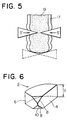
- a conventional device as shown in Fig. 5, where wedge-formed blades are used, the blades move in the radially inward direction.
- the blades intrude into the filling 19 as indicated by arrows s', while increasing the contact area of the blades with the cylindrical body.
- the cylindrical body receives force along the loci of the movements of the sliding surfaces 3 in a circumferentially biased direction, so that the dough crust is brought to the centre of the opening 14 and is eventualy cut by the closure of the opening 14.
- the friction between the dough crust and the sliding surfaces induces the dough to flow in the direction s.
- the opening is filled only with the dough crust, the filling having been displaced to either side of the opening.
- the cylindrical crust is finally cut as shown in Figs. 4(A) and 4(B) and a shaped body 21 is produced.
- the contact area of the sliding surfaces with the cylindrical body, when closing the opening, can be further reduced, as shown in Fig. 6, by providing a member 2 with slopes 8 at its inner end. Whilst the embodiment of Figure 6 shows two slopes, it will be appreciated that a single slope may also be provided. One of the slopes 8 is formed by cutting the corner formed by the two adjoining inner sliding surfaces 4 and 6 and the top surface of the member. The other slope can be formed in the similar manner at the corner formed by the same two sliding surfaces and the bottom surface of the member. As will be understood from Fig. 6, illustrating a perspective view of the member 2, it has a sliding surface 4 with a height a , a sliding surface 6, the slopes 8, and an edge 10.
- slopes 8 have a negative gradient toward the inner end of the member 2.
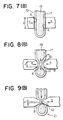
- an assembly 16 is made by combining six members 2 to provide an opening 22, which is adapted to pass the cylindrical body 15.
- the walls 18 made by the exposed part of the sliding surfaces 4 have a height a at a position where no slope is provided when the opening is fully opened as shown in Fig. 7(B), along with the progress of the sliding movement of the members 2 in the direction S, the height of the walls are reduced. Since the slopes are vertically formed, the cylindrical body is surrounded by serrated walls. A cross-section of the cylindrical body and the members is shown in Fig. 8(B), wherein the height of the walls is shown as a '.
- the surface area of the cylindrical body 15 contacting the walls 18 decreases so that the constriction of the cylindrical body 15 by the walls 18 is smoothly made.
- the edges 10 converge as shown in Figs. 9(A) and 9(B), and the cylindrical body 15 is cut to shape the spherical body 21.
- the height of the walls 18 is reduced to a ''.
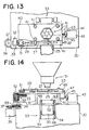
- the apparatus is composed of a base 20, a cutter device 23, a cylindrical body supply device 51, and a belt conveyor 53.
- the cutter device 23 comprises a frame 40, the case 11 mounted on the frame 40 and accommodating the members 1, and a slider 27.
- the frame 40 is adapted to slide upwards or downwards as explained later, along supporting shafts 41 which are mounted on the base 20.
- a pin 25 is connected at one end, through a slot formed on the case 11, to the outer sliding surface 9 of one of the members 1, and another end of the pin 25 is fixed to the slider 27 near an end.
- the other end of the slider 27 is connected to an end of a crank rod 29.
- crank rod 29 is rotatably connected by means of a pin to a point near the circumference of a disc 31.
- the disc 31 is concentrically and fixedly connected to a gear which is adapted to rotate by a slide gear 33 supported by a bracket 32 mounted on the base 20.
- the slide gear 33 can be rotated by a motor 39 through its own shaft 34 and gears 35 and 37. When the motor 39 starts, the slider 27 repeatedly moves back and forth and slides the members 1 in the case 11.
- One end of a pin 49 is fixedly connected to an end of the cutter device 23, and the other end of the pin 49 is rotatably connected to an end of a crank rod 47.
- the other end of the crank rod 47 is rotatably connected to an end of a pin 44.
- the other end of the pin 44 is fixedly connected to a disc 45 at a point near the circumference thereof.
- the disc 45 is connected to and rotated by a motor 43 to cause the crank rod 47 to move downwards and upwards, whereby the cutter device 23 can be repeatedly lowered and lifted.
- the belt conveyor 53 is composed of a conveyor frame 54, rollers 48, 55, and 57, two tension rollers 52, a belt 50, and a motor (not shown) for driving the belt conveyor 53.
- Fig. 15 it will be understood that one end of the belt conveyor 53 is made to move upwards and downwards by a conveyor lifting device 46 mounted on the base 20, so that the roller 57 is swung about the roller 55, to avoid deformation of the spherical body as explained earlier.
- the cylindrical body 15 is continuously fed from the supply device 51 and is constricted by the cutter device 23 in a direction perpendicular to the axis of the cylindrical body to form a spherical body 21, which is fed onto the next station by the belt conveyor 53.
- the closing and opening of the opening 14 may be carried out even without reciprocating the cutter device.
- the feeding speed of the cylindrical body is slow, the closing and opening of the opening 14 may be carried out even without reciprocating the cutter device.
- the movement of the cutter device 23 is such that it descends at the same speed as that of the feeding speed of the cylindrical body, and ascends after a spherical body is formed.
- the members are made to slide back to their original opened position during or before the ascent of the cutter device to avoid the members colliding with the cylindrical body. Repeating the aforesaid operation, the cylindrical body is continuously cut to form spherical bodies at a high speed.
- the spherically shaped body 21 can be received by the belt conveyor 53 lifted by the conveyor lifting device 46.
- the conveyor lifting device 46 is adapted to alternately lower and raise the belt conveyor 53 in synchronisation with the movements of the assembly of the cutter device.
- FIG. 16(A) an assembly 76 is composed of four rectangular parallelipiped members 77, each having a slope 79 at a corner, sliding surfaces 78 and 87, and an edge 80. Part of a sliding surface 78 of each member forms walls 81 defining an opening 83, and each member slides in a direction s. When the opening 83 is closed, the position of the members is shown in Fig. 16(B).
- An assembly can be composed of three parallelopiped members, each having a curved slope 85, sliding surfaces 86 and 92, and an edge 88. Walls 90, formed by a sliding surface 86 of each member make an opening 91, and each member slides in a direction s. When the opening 91 is closed, the position of the members is shown in Fig. 17(B).
- the constriction of the cylindrical body is carried out while the contact area of the walls of the opening with the surface of the cylindrical body is gradually decreased. Therefore, no force is applied to cause the members to penetrate the body, unlike the conventional apparatus using wedge-formed blades. As a result, the filling is readily moved in the axial direction without breaking the dough crust.
- the members slide in a tangentially biased direction relative to the circumference of the cylindrical body. Accordingly, the dough crust is narrowed to a point at which a spherical body is shaped without exposing the filling.
- a relatively simple mechanism can produce at high speed spherical bodies made of dough crust and a filling of high quality.
Landscapes
- Engineering & Computer Science (AREA)
- Life Sciences & Earth Sciences (AREA)
- Food Science & Technology (AREA)
- Mechanical Engineering (AREA)
- Manufacturing And Processing Devices For Dough (AREA)
- Confectionery (AREA)
- General Preparation And Processing Of Foods (AREA)
- Transition And Organic Metals Composition Catalysts For Addition Polymerization (AREA)
- Pharmaceuticals Containing Other Organic And Inorganic Compounds (AREA)
- Acyclic And Carbocyclic Compounds In Medicinal Compositions (AREA)
- Formation And Processing Of Food Products (AREA)
Claims (6)
- Vorrichtung zum Bilden bzw. Formen eines kugelförmigen Körpers, der einen Teigrand und eine Füllung aufweist, umfassend eine Einrichtung zum Zuführen eines zylindrischen Körpers (15), der einen Teigrand (17) und eine Füllung (19) aufweist, ein Gebilde, welches eine Mehrzahl von auf einem Umfang angeordneten Gliedern (1, 2) aufweist, die kombiniert sind, um eine Öffnung (14, 22) an ihrer Mitte zu bilden, durch welche der zylindrische Körper (15) hindurchgehen kann, wobei das Gebilde stromabwärts der Einrichtung zum Zuführen des zylindrischen Körpers (15) angeordnet ist, eine Einrichtung (25) zum Schließen und Öffnen der Öffnung des Gebildes, um einen kugelförmigen Körper (21) aus dem zylindrischen Körper (15) zu bilden, und eine Einrichtung (53), die stromabwärts des Gebildes zum Aufnehmen des gebildeten kugelförmigen Körpers (21) angeordnet ist, wobei das genannte Gebilde wenigstens drei Glieder (1, 2) aufweist, deren jedes wenigstens zwei Gleitflächen (3, 5, 4, 6) hat und die so kombiniert sind, daß eine Gleitfläche (3, 4) eines Gliedes (1, 2) an einer Gleitfläche (5, 6) eines anderen Gliedes (1, 2) gleiten kann,
dadurch gekennzeichnet,
daß die Öffnung (14, 22) durch Wände bestimmt ist, die sich in Richtung der Zufuhr des Teigrandes (17) und der Füllung (19) erstrecken und die nach innen freiliegenden Teile der Gleitflächen (3, 4) der Glieder (1, 2) aufweisen und durch das Gleiten der Glieder (1, 2) aneinander geöffnet und geschlossen werden, und daß die Wände derart ausgeführt sind, daß während des Schließens der Öffnung der zylindrische Körper (15) entlang eines Abschnitts seiner Länge eingeschnürt wird, um die Füllung (19) zu zwingen, sich in axialer Richtung des zylindrischen Körpers (15) zu bewegen, ohne den Teigrand (17) aufzubrechen, wobei der Teigrand (17) dann zur Mitte der Öffnung gebracht und durch im wesentlichen vollständiges Schließen der Öffnung abgeschnitten wird. - Vorrichtung nach Anspruch 1, wobei jedes der Glieder (2) wenigstens eine Abschrägung (8) eines negativen Gradienten in Richtung gegen das Innenende der Gleitflächen (4, 6) des Gliedes (2) hat, wodurch die Höhe der Wand, betrachtet in Richtung der Zufuhr des Teigrandes (17) und der Füllung (19) allmählich verringert wird, wenn die Glieder (2) gleiten, um die Öffnung (22) zu schließen.
- Vorrichtung nach Anspruch 2, umfassend eine Einrichtung (43, 47) zum Absenken und Heben des Gebildes, wodurch das Absenken des Gebildes mit dem Absenken des zylindrischen Körpers (15) synchronisiert werden kann.
- Vorrichtung nach Anspruch 1 oder 2, umfassend eine Einrichtung (20, 45) zum wiederholten Absenken und Heben der Aufnahmeeinrichtung (53) zum Aufnehmen des kugelförmigen Körpers (21) in Synchronisation mit dem Bilden oder Formen des kugelförmigen Körpers (21).
- Verfahren zum Bilden oder Formen eines kugelförmigen Körpers, der aus einem Teigrand (17) und einer Füllung (19) besteht, umfassend kontinuierliches Zuführen eines zylindrischen Körpers (15), der aus einem Teigrand (17) und einer Füllung (19) besteht, Anlegen einer Umfangseinschnürkraft an den zylindrischen Körper rechtwinklig zu dessen Achse, und Anlegen von Kraft an den zylindrischen Körper (15) in wenigstens drei Richtungen von ihm und entlang der geometrischen Orte der Gleitbewegungen von wenigstens drei Gliedern (1, 2), die eine Öffnung bilden und rund um den zylindrischen Körper (15) ausgerichtet sind sowie aneinander gleiten derart, daß sie den zylindrischen Körper (15) berühren,
gekennzeichnet durch das Schließen der Öffnung und das Einschnüren des zylindrischen Körpers (15) entlang eines Abschnitts seiner Länge, um die Füllung (19) zu zwingen, sich in der axialen Richtung des zylindrischen Körpers (15) zu bewegen, ohne den Teigrand (17) aufzubrechen, wonach der Teigrand zur Mitte der Öffnung gebracht und der zylindrische Körper (15) durch im wesentliches vollständiges Schließen der Öffnung abgeschnitten wird. - Verfahren nach Anspruch 5, wobei der Körper (15) in Abwärtsrichtung zugeführt wird und die Glieder (1, 2) wiederholt abgesenkt und gehoben werden, und das Absenken des zylindrischen Körpers und der Glieder (1, 2) synchronisiert wird, während die Einschnürungskraft an den zylindrischen Körper (15) angelegt wird.
Applications Claiming Priority (4)
| Application Number | Priority Date | Filing Date | Title |
|---|---|---|---|
| JP6925/86 | 1986-01-16 | ||
| JP692586A JPS62166850A (ja) | 1986-01-16 | 1986-01-16 | 包被切断方法 |
| JP27587/86 | 1986-02-11 | ||
| JP61027587A JPS62186751A (ja) | 1986-02-11 | 1986-02-11 | 包被切断方法及び装置 |
Publications (3)
| Publication Number | Publication Date |
|---|---|
| EP0230368A2 EP0230368A2 (de) | 1987-07-29 |
| EP0230368A3 EP0230368A3 (en) | 1987-11-19 |
| EP0230368B1 true EP0230368B1 (de) | 1993-05-12 |
Family
ID=26341148
Family Applications (1)
| Application Number | Title | Priority Date | Filing Date |
|---|---|---|---|
| EP87300262A Expired - Lifetime EP0230368B1 (de) | 1986-01-16 | 1987-01-13 | Herstellung eines kugelförmigen Körpers |
Country Status (11)
| Country | Link |
|---|---|
| US (2) | US4734024A (de) |
| EP (1) | EP0230368B1 (de) |
| KR (1) | KR900003436B1 (de) |
| CN (1) | CN1009798B (de) |
| AT (1) | ATE89120T1 (de) |
| AU (1) | AU568252B2 (de) |
| CA (1) | CA1265389A (de) |
| DE (1) | DE3785767T2 (de) |
| ES (1) | ES2002502A6 (de) |
| SG (1) | SG125294G (de) |
| SU (1) | SU1679961A3 (de) |
Families Citing this family (59)
| Publication number | Priority date | Publication date | Assignee | Title |
|---|---|---|---|---|
| JPS62278933A (ja) * | 1986-05-26 | 1987-12-03 | レオン自動機株式会社 | 包被切断装置 |
| JPS62278934A (ja) * | 1986-05-26 | 1987-12-03 | レオン自動機株式会社 | 包被切断装置 |
| JPH0748994B2 (ja) * | 1987-02-25 | 1995-05-31 | 将男 小林 | 固形食品材料を可塑性食品材料で被覆した団塊状被覆食品の製造装置 |
| JPH02227062A (ja) * | 1988-08-12 | 1990-09-10 | Masao Kobayashi | 団塊状包被食品成形装置 |
| US4936203A (en) * | 1988-09-03 | 1990-06-26 | Rheon Automatic Machinery Co., Ltd. | Apparatus for shaping and arraying spheroidal bodies of food materials |
| DE3880492T2 (de) * | 1988-12-15 | 1993-08-26 | Frisco Findus Ag | Formmaschine fuer speiseeis. |
| US5190770A (en) * | 1989-01-12 | 1993-03-02 | Rheon Automatic Machinery Co., Ltd. | Apparatus for cutting and shaping a spherical body |
| JPH03175925A (ja) * | 1989-12-01 | 1991-07-31 | Rheon Autom Mach Co Ltd | 包被球断装置 |
| GB8901987D0 (en) * | 1989-01-30 | 1989-03-22 | Matthews Bernard Plc | Improvements in the manufacture of food stuffs |
| JPH03285632A (ja) * | 1990-03-30 | 1991-12-16 | Rheon Autom Mach Co Ltd | 包被球断装置 |
| JP2916515B2 (ja) * | 1990-05-01 | 1999-07-05 | レオン自動機 株式会社 | 包被球断装置 |
| US5069921A (en) * | 1990-06-25 | 1991-12-03 | Madanat Edward A | Method of preparing an encrusted food product |
| AU643818B2 (en) * | 1990-09-12 | 1993-11-25 | Rheon Automatic Machinery Co. Ltd. | Apparatus for cutting an enveloped body |
| US5223277A (en) * | 1990-09-12 | 1993-06-29 | Rheon Automatic Machinery Co., Ltd. | Apparatus for cutting an enveloped body |
| DK126491D0 (da) * | 1991-06-27 | 1991-06-27 | Poul Erik Brink | Fremgangsmaade og apparat til omfoldning af vingedele paa flade dejemner |
| US5820890A (en) * | 1992-01-30 | 1998-10-13 | Kobird Co., Ltd. | Apparatus for cutting plastic bar-shaped food |
| JPH084443B2 (ja) * | 1992-01-30 | 1996-01-24 | 株式会社コバード | 可塑性棒状食品切断機 |
| TW215897B (de) * | 1992-02-06 | 1993-11-11 | Reon Zidoki Kk | |
| TW213852B (de) * | 1992-03-30 | 1993-10-01 | Reon Zidoki Kk | |
| WO1993024025A1 (fr) * | 1992-05-26 | 1993-12-09 | Kobird Co., Ltd. | Procede et appareil de production d'aliments plastiques |
| TW253831B (de) * | 1993-06-11 | 1995-08-11 | Reon Zidoki Kk | |
| TW339262B (en) * | 1993-08-26 | 1998-09-01 | Kenbart Kk | Method of cutting strip-shaped food and the device |
| TW306868B (de) * | 1995-03-07 | 1997-06-01 | Reon Zidoki Kk | |
| US5643617A (en) * | 1996-01-24 | 1997-07-01 | Burtscher; Gunther | Apparatus for scaling and molding pieces of dough |
| US6907808B2 (en) * | 1996-02-02 | 2005-06-21 | Brigitte Merritt | Apparatus for the processing of a strip of plastic material |
| JP2860937B2 (ja) * | 1996-08-08 | 1999-02-24 | レオン自動機株式会社 | フチ付き製品の製造方法および装置 |
| AU689412B1 (en) * | 1996-09-25 | 1998-03-26 | Rheon Automatic Machinery Co. Ltd. | Apparatus for cutting and shaping a spherical body |
| JP3016246B2 (ja) * | 1996-09-25 | 2000-03-06 | レオン自動機株式会社 | 包被切断装置 |
| GB2324978B (en) * | 1997-05-03 | 2001-06-27 | United Biscuits Ltd | Method and apparatus for producing food products |
| JP2934206B2 (ja) * | 1997-05-19 | 1999-08-16 | レオン自動機株式会社 | 食品材料接合吐出装置、及び食品成形機 |
| WO1999002039A1 (en) | 1997-07-09 | 1999-01-21 | Kraft Foods, Inc. | Dough enrobed cheese filling |
| US6257863B1 (en) | 1997-10-31 | 2001-07-10 | Industrial Thermo Polymers Limited | Extruder dies with shaping means |
| DE29801553U1 (de) | 1998-02-03 | 1998-05-20 | Schäfer, Helmut, 72070 Tübingen | Vorrichtung zum Portionieren von Teig |
| CA2267605C (en) * | 1998-04-01 | 2002-04-16 | Rheon Automatic Machinery Co., Ltd. | Apparatus for cutting and shaping food products |
| TW359079U (en) * | 1998-09-30 | 1999-05-21 | Yu Ouyang | Improvement of knife blade for the forming tool in food processor |
| US6234779B1 (en) * | 2000-02-18 | 2001-05-22 | Robert Ou-Young | Method of shaping a spherical body and apparatus therefor |
| US6263788B1 (en) * | 2001-02-09 | 2001-07-24 | Chin-Ta Chiang | Food extrusion apparatus |
| JP3432498B2 (ja) * | 2001-02-20 | 2003-08-04 | レオン自動機株式会社 | 包あん機 |
| US6776601B2 (en) * | 2001-04-24 | 2004-08-17 | Antonio Cimenti | Dough portion control machine for flour and similar materials |
| US6477944B1 (en) * | 2002-05-28 | 2002-11-12 | Robert Ou-Young | Molding device for pastry products |
| NZ533438A (en) * | 2002-10-18 | 2006-11-30 | Rheon Automatic Machinery Co | Apparatus and method for manufacturing bread |
| US20040107806A1 (en) * | 2002-12-10 | 2004-06-10 | Gruber Thomas A. | Tool assembly with interchangeable iris actuating frame |
| RU2287278C1 (ru) * | 2005-02-22 | 2006-11-20 | Александр Григорьевич Соловьев | Устройство для формования и нарезания отдельных изделий |
| US7478590B2 (en) * | 2006-12-06 | 2009-01-20 | Robert Ou-Young | Folding control apparatus for left and right lateral pieces of slice food |
| CN102186357B (zh) * | 2008-10-17 | 2013-11-06 | 荷兰联合利华有限公司 | 制备冷冻甜品的方法 |
| US20100285187A1 (en) * | 2009-05-08 | 2010-11-11 | Weinstein James N | Apparatus and methods for cutting individual pieces from a food extrudate |
| TWI386162B (zh) * | 2009-09-16 | 2013-02-21 | Kobird Co Ltd | 甜甜圈形食品成形裝置及方法 |
| WO2012080282A1 (en) | 2010-12-16 | 2012-06-21 | Unilever Plc | Process for preparing frozen confectionery products |
| US9192176B2 (en) | 2011-09-15 | 2015-11-24 | Conopco, Inc. | Process for producing frozen confectionery products |
| CN103222488A (zh) * | 2013-01-10 | 2013-07-31 | 安徽维斯达食品机械有限公司 | 多瓣捏花成形刀具总成 |
| CN107087658B (zh) * | 2016-02-17 | 2021-11-26 | 哈斯食品设备有限责任公司 | 用于切割挤出机输入的面团的方法和装置 |
| EP3207803A1 (de) | 2016-02-17 | 2017-08-23 | Haas Food Equipment GmbH | Verfahren und vorrichtung zum schneiden der teigausgabe mit einer extrusionsmaschine |
| ES2863409T3 (es) * | 2016-09-02 | 2021-10-11 | Handtmann Albert Maschf | Dispositivo y procedimiento para conformar y dividir al menos una tira pastosa de alimento en productos en forma de rodaja |
| US20180065317A1 (en) * | 2016-09-06 | 2018-03-08 | Cc3D Llc | Additive manufacturing system having in-situ fiber splicing |
| CN106213558A (zh) * | 2016-09-14 | 2016-12-14 | 上海沃敉奥机电设备有限公司 | 切刀联动组合装置 |
| EP3809853A4 (de) | 2018-05-14 | 2022-05-04 | Solen Cikolata Gida Sanayi Ve Ticaret Anonim Sirketi | Produktionsanordnung und verfahren für koextrudiertes gefülltes essbares produkt |
| CN110402979A (zh) * | 2019-08-22 | 2019-11-05 | 广东傲迪自动化科技有限公司 | 一种面粉皮卷棍生产线 |
| IT201900020823A1 (it) * | 2019-11-11 | 2021-05-11 | Marotta Evolution S R L | Apparecchiatura per la produzione di formaggi ripieni, particolarmente burrate |
| US12260183B2 (en) * | 2021-09-16 | 2025-03-25 | International Business Machines Corporation | Geometric shape based event component personalization |
Family Cites Families (9)
| Publication number | Priority date | Publication date | Assignee | Title |
|---|---|---|---|---|
| DE272176C (de) * | ||||
| US2578229A (en) * | 1947-11-17 | 1951-12-11 | Clement Marcel Rene | Draw plate |
| DE1454966A1 (de) * | 1964-08-01 | 1969-04-10 | Basf Ag | Verfahren und Vorrichtung zur Herstellung von Hohlkoerpern aus thermoplastischen Kunststoffen im Blasverfahren |
| US3901641A (en) * | 1971-06-24 | 1975-08-26 | Alusuisse | Compacting step by step |
| US4155973A (en) * | 1976-07-19 | 1979-05-22 | Klein Gerald B | Process for the manufacture of a tapered leader |
| US4251201A (en) * | 1978-09-18 | 1981-02-17 | Krysiak Janusz D | Extrusion apparatus |
| JPS6024157Y2 (ja) * | 1983-06-03 | 1985-07-18 | レオン自動機株式会社 | 可塑性物質の包被球断装置 |
| JPS60105482A (ja) * | 1983-06-24 | 1985-06-10 | ナビスコ ブランズ インコ−ポレ−テツド | フード・ピースの製造方法 |
| JPS6085178U (ja) | 1983-11-18 | 1985-06-12 | 梶原工業株式会社 | 食品切断装置 |
-
1986
- 1986-08-09 US US06/900,074 patent/US4734024A/en not_active Expired - Lifetime
- 1986-09-03 KR KR1019860007391A patent/KR900003436B1/ko not_active Expired
- 1986-09-08 SU SU864028230A patent/SU1679961A3/ru active
- 1986-09-10 AU AU62624/86A patent/AU568252B2/en not_active Expired
- 1986-09-29 ES ES8602266A patent/ES2002502A6/es not_active Expired
- 1986-10-13 CN CN86106548A patent/CN1009798B/zh not_active Expired
-
1987
- 1987-01-06 CA CA000526710A patent/CA1265389A/en not_active Expired - Lifetime
- 1987-01-13 AT AT87300262T patent/ATE89120T1/de not_active IP Right Cessation
- 1987-01-13 DE DE8787300262T patent/DE3785767T2/de not_active Expired - Lifetime
- 1987-01-13 EP EP87300262A patent/EP0230368B1/de not_active Expired - Lifetime
-
1988
- 1988-01-28 US US07/149,538 patent/US4883678A/en not_active Expired - Lifetime
-
1994
- 1994-08-26 SG SG125294A patent/SG125294G/en unknown
Also Published As
| Publication number | Publication date |
|---|---|
| CN1009798B (zh) | 1990-10-03 |
| DE3785767D1 (de) | 1993-06-17 |
| CN86106548A (zh) | 1987-07-29 |
| AU6262486A (en) | 1987-07-23 |
| ATE89120T1 (de) | 1993-05-15 |
| KR870006978A (ko) | 1987-08-13 |
| SG125294G (en) | 1995-01-13 |
| EP0230368A2 (de) | 1987-07-29 |
| KR900003436B1 (ko) | 1990-05-19 |
| EP0230368A3 (en) | 1987-11-19 |
| SU1679961A3 (ru) | 1991-09-23 |
| CA1265389A (en) | 1990-02-06 |
| AU568252B2 (en) | 1987-12-17 |
| US4734024A (en) | 1988-03-29 |
| DE3785767T2 (de) | 1993-08-12 |
| ES2002502A6 (es) | 1988-08-16 |
| US4883678A (en) | 1989-11-28 |
Similar Documents
| Publication | Publication Date | Title |
|---|---|---|
| EP0230368B1 (de) | Herstellung eines kugelförmigen Körpers | |
| US4767304A (en) | Apparatus for shaping a spherical body | |
| US4767305A (en) | Apparatus for shaping a spherical body | |
| RU2188549C2 (ru) | Устройство для непрерывного нарезания и формования пищевого продукта (варианты) и способ его осуществления (варианты) | |
| AU650196B2 (en) | Method and apparatus for continuously manufacturing filled buns | |
| US3653336A (en) | Automatic molding apparatus for producing ring-shaped doughnuts containing fillings | |
| KR900002727A (ko) | 단괴형상의 포피식품 성형장치 | |
| HU208783B (en) | Apparatus for producing foodstuff composed of wrapping layer and core | |
| JP2860937B2 (ja) | フチ付き製品の製造方法および装置 | |
| JPH046322B2 (de) | ||
| JPS6352863B2 (de) | ||
| DD249177A5 (de) | Einrichtung und verfahren zur formung eines sphaerischen koerpers | |
| JPH08112056A (ja) | 多層包被食品の製造方法 | |
| KR880001471B1 (ko) | 포피구형 식품제조장치 | |
| JP2854820B2 (ja) | がんもどき素材の成形方法 | |
| JPH0420218Y2 (de) | ||
| JP2001204409A (ja) | 米飯成形装置 | |
| JP2014212721A (ja) | 食品成形方法および装置 | |
| JPS62239970A (ja) | 肉まんじゆうの製造方法および装置 | |
| JPH06269268A (ja) | 食品材料の成形切断装置 | |
| JPH0478253B2 (de) | ||
| JPH0455838B2 (de) |
Legal Events
| Date | Code | Title | Description |
|---|---|---|---|
| PUAI | Public reference made under article 153(3) epc to a published international application that has entered the european phase |
Free format text: ORIGINAL CODE: 0009012 |
|
| AK | Designated contracting states |
Kind code of ref document: A2 Designated state(s): AT BE CH DE FR GB IT LI NL SE |
|
| PUAL | Search report despatched |
Free format text: ORIGINAL CODE: 0009013 |
|
| AK | Designated contracting states |
Kind code of ref document: A3 Designated state(s): AT BE CH DE FR GB IT LI NL SE |
|
| 17P | Request for examination filed |
Effective date: 19880107 |
|
| 17Q | First examination report despatched |
Effective date: 19891128 |
|
| GRAA | (expected) grant |
Free format text: ORIGINAL CODE: 0009210 |
|
| ITF | It: translation for a ep patent filed | ||
| AK | Designated contracting states |
Kind code of ref document: B1 Designated state(s): AT BE CH DE FR GB IT LI NL SE |
|
| REF | Corresponds to: |
Ref document number: 89120 Country of ref document: AT Date of ref document: 19930515 Kind code of ref document: T |
|
| REF | Corresponds to: |
Ref document number: 3785767 Country of ref document: DE Date of ref document: 19930617 |
|
| ET | Fr: translation filed | ||
| EAL | Se: european patent in force in sweden |
Ref document number: 87300262.0 |
|
| REG | Reference to a national code |
Ref country code: GB Ref legal event code: IF02 |
|
| PGFP | Annual fee paid to national office [announced via postgrant information from national office to epo] |
Ref country code: DE Payment date: 20060105 Year of fee payment: 20 Ref country code: SE Payment date: 20060105 Year of fee payment: 20 |
|
| PGFP | Annual fee paid to national office [announced via postgrant information from national office to epo] |
Ref country code: FR Payment date: 20060110 Year of fee payment: 20 |
|
| PGFP | Annual fee paid to national office [announced via postgrant information from national office to epo] |
Ref country code: AT Payment date: 20060111 Year of fee payment: 20 Ref country code: GB Payment date: 20060111 Year of fee payment: 20 |
|
| PGFP | Annual fee paid to national office [announced via postgrant information from national office to epo] |
Ref country code: CH Payment date: 20060113 Year of fee payment: 20 |
|
| PGFP | Annual fee paid to national office [announced via postgrant information from national office to epo] |
Ref country code: NL Payment date: 20060115 Year of fee payment: 20 |
|
| PGFP | Annual fee paid to national office [announced via postgrant information from national office to epo] |
Ref country code: IT Payment date: 20060131 Year of fee payment: 20 |
|
| PGFP | Annual fee paid to national office [announced via postgrant information from national office to epo] |
Ref country code: BE Payment date: 20060307 Year of fee payment: 20 |
|
| PG25 | Lapsed in a contracting state [announced via postgrant information from national office to epo] |
Ref country code: GB Free format text: LAPSE BECAUSE OF EXPIRATION OF PROTECTION Effective date: 20070112 |
|
| PG25 | Lapsed in a contracting state [announced via postgrant information from national office to epo] |
Ref country code: NL Free format text: LAPSE BECAUSE OF EXPIRATION OF PROTECTION Effective date: 20070113 |
|
| REG | Reference to a national code |
Ref country code: GB Ref legal event code: PE20 |
|
| REG | Reference to a national code |
Ref country code: CH Ref legal event code: PL |
|
| NLV7 | Nl: ceased due to reaching the maximum lifetime of a patent |
Effective date: 20070113 |
|
| EUG | Se: european patent has lapsed | ||
| BE20 | Be: patent expired |
Owner name: *RHEON AUTOMATIC MACHINERY CO. LTD Effective date: 20070113 |
|
| PLBE | No opposition filed within time limit |
Free format text: ORIGINAL CODE: 0009261 |
|
| STAA | Information on the status of an ep patent application or granted ep patent |
Free format text: STATUS: NO OPPOSITION FILED WITHIN TIME LIMIT |