EP0225622A2 - Dispositif pour bloquer des boulons contre la rotation - Google Patents
Dispositif pour bloquer des boulons contre la rotation Download PDFInfo
- Publication number
- EP0225622A2 EP0225622A2 EP86117027A EP86117027A EP0225622A2 EP 0225622 A2 EP0225622 A2 EP 0225622A2 EP 86117027 A EP86117027 A EP 86117027A EP 86117027 A EP86117027 A EP 86117027A EP 0225622 A2 EP0225622 A2 EP 0225622A2
- Authority
- EP
- European Patent Office
- Prior art keywords
- holder
- drivers
- driver
- screw bolts
- adapter
- Prior art date
- Legal status (The legal status is an assumption and is not a legal conclusion. Google has not performed a legal analysis and makes no representation as to the accuracy of the status listed.)
- Granted
Links
- 238000005096 rolling process Methods 0.000 claims description 2
- 239000000969 carrier Substances 0.000 description 3
- 230000015572 biosynthetic process Effects 0.000 description 1
- 230000006835 compression Effects 0.000 description 1
- 238000007906 compression Methods 0.000 description 1
- 230000008878 coupling Effects 0.000 description 1
- 238000010168 coupling process Methods 0.000 description 1
- 238000005859 coupling reaction Methods 0.000 description 1
- 230000002349 favourable effect Effects 0.000 description 1
Images

Classifications
-
- F—MECHANICAL ENGINEERING; LIGHTING; HEATING; WEAPONS; BLASTING
- F16—ENGINEERING ELEMENTS AND UNITS; GENERAL MEASURES FOR PRODUCING AND MAINTAINING EFFECTIVE FUNCTIONING OF MACHINES OR INSTALLATIONS; THERMAL INSULATION IN GENERAL
- F16B—DEVICES FOR FASTENING OR SECURING CONSTRUCTIONAL ELEMENTS OR MACHINE PARTS TOGETHER, e.g. NAILS, BOLTS, CIRCLIPS, CLAMPS, CLIPS OR WEDGES; JOINTS OR JOINTING
- F16B39/00—Locking of screws, bolts or nuts
- F16B39/02—Locking of screws, bolts or nuts in which the locking takes place after screwing down
- F16B39/10—Locking of screws, bolts or nuts in which the locking takes place after screwing down by a plate, spring, wire or ring immovable with regard to the bolt or object and mainly perpendicular to the axis of the bolt
Definitions
- the invention relates to a device for preventing undesired rotation of screw bolts or the like provided at their ends with key engagement surfaces, in particular for large screw bolts.
- the object of the invention is to provide a practical, easy-to-use and simple device with which an undesired rotation of screw bolts can be prevented, in particular for needs of the type described above or similar. Further problems with which the invention is concerned arise itself from the respective explanation of the solution shown.
- the device according to the invention is characterized by the features specified in claim 1. As important components, it contains a holder, at least two drivers assigned to the latter and a number of individual adapters.
- Such a device makes it very easy to secure screw bolts in pairs against undesired turning. A torque that occurs on a screw bolt and seeks to turn it is reliably absorbed by the device and the torque support provided thereby. Depending on the need and the existing requirements, such a device can always remain in its place and then be practically part of a corresponding arrangement or device, or the device can only be used when necessary and for as long as is necessary for the operation to be carried out, such as unscrewing a nut.
- the drivers each extend through an opening of the holder, stops being provided in this area to limit the angular mobility.
- the stops can in particular be formed by inner surfaces of the opening itself.
- the opening expediently has the shape of a polygon, the driver or an extension of the same then having a corresponding shape with somewhat smaller dimensions.
- elastic centering elements are present which hold the driver in a rest or starting position relative to the holder.
- Such centering elements can be designed in different ways.
- spring-loaded thrust pieces are provided on or in the driver, which bear against inner surfaces of the holder.
- the adapters can be connected directly or indirectly to the holder or can be coupled thereto in such a way that they can be transported together with the holder and the drivers, in particular when the device is removed.
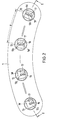
- Fig. 1 illustrates a particularly important application of the device, namely for bolts, expansion bolts, tie rods or the like.
- cover closures or flange connections for reactor vessels, pressure vessels and other high-strength connections, in particular in the manner of stud bolts are screwed with their lower end into a receiving thread of a base body and the like through holes in a cover, flange or the like. go through.
- a fastening nut is screwed onto a corresponding thread of the bolt, or the like against the cover, flange. sets.
- Such bolts are usually preloaded with a special device, i.e. stretched with a certain tensile force before the fastening nut is finally tightened. After removing the axial tensile force, a tension remains, so that the fastening nut or the like not only snugly on the cover, flange. is present, but presses the latter firmly against its support.
- Fig. 1 the upper parts of bolts 20 of the type mentioned above can be seen, which with their lower ends in a base body, not shown, e.g. a reactor vessel, are screwed in. They have key engagement surfaces at the upper end, here in the form of an external hexagon 21.
- Numeral 22 denotes a nut screwed onto an upper thread of the screw bolt 20, which serves as a system for an underlying, e.g. hydraulic tensioning or stretching device. This can contain one or more pistons which can be displaced upwards in cylinders, the uppermost piston acting on the contact nut 22.
- the upper contact nuts 22 must first be unscrewed from the bolts 20. It may happen that the nut is still tight and therefore does not turn on the bolt, but that the bolt is undesirably rotated together with the nut under the action of a torque applied to the latter.
- a plate-shaped holder 1 with carrying handles 2 is equipped with four sleeve-like carriers 3 in the advantageous embodiment shown.
- the center distance A of the driver 3 is equal to the center distance of the bolts 20 from each other. Because the bolts are arranged on a bolt circle in the assumed case, the driver 3 are also to correspond the places of an arc in the holder. The outer shape of the latter can then also be curved, as shown in FIG. 2.
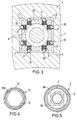
- Each driver 3 has a cylindrical, approximately pot-shaped lower part 3a with an internal toothing 4, a cylindrical middle part 3b and then, on a collar 3c, an upper projection 3d of approximately square outer shape with the side surfaces 5.
- the projection 3d passes through an opening delimited by surfaces 7 6 in the holder 1 (see. Fig. 3), which also has a square shape, but is slightly larger than the approach 3d, so that there is a small gap.
- the driver 3 has a small angular mobility in the sense of a rotation in one direction or the other about its longitudinal axis L from the starting position shown in FIG. 3. Such rotation is limited by the inner surfaces 7 acting as stops, against which the corner regions of the outer surfaces 6 of the projection 3d can come to rest.
- pressure pieces 10 loaded by compression springs 9 are provided in transverse bores 8 of the projection 3d, which are supported with their rounded heads on the inner surfaces 7 of the opening 6.
- the pressure pieces 10 are all shown as lying at the same height. However, an arrangement in two planes can also be provided, which results in particularly favorable centering or restoring forces.
- a head piece 13 is detachably connected, for example by, to the end face of the projection 3d of each driver 3 Screws, which has a larger diameter than the opening 6 in a round shape so that it rests on the top of the holder 1.
- the driver 3 is suspended to a certain extent on the holder 1.
- the distance between the head piece 13 and the collar 3c is somewhat larger than the thickness of the holder 1, so that there is also little mobility of the driver 3 relative to the holder 1 in the axial direction. But it is also possible to detachably attach the head pieces 13 to the holder 3.
- the number 12 designates adapters that form separate parts for themselves, but can be coupled to the drivers 3 or to the holder 1.
- Each adapter 12 has a lower part designed as a plug-on head 12a, which in the example shown has an internal hexagon 11, which corresponds to the external hexagon 21 at the upper end of each screw bolt 20. If the bolts have a different type or arrangement of key engagement surfaces, the formation of counter surfaces on or in the adapters is naturally a different one. For example, there may be a square or an elongated opening.
- the plug-on head 12a of the adapter 12 is also provided with external teeth 14 with which the internal teeth 4 of the driver 3 can engage.
- the teeth of the external toothing 14 of the adapter 12 and / or the teeth of the internal toothing 4 of the driver 3 are expediently pointed or chamfered at one end in order to enable particularly easy sliding into one another.
- a shaft 12b extends from the plug-on head 12a of the adapter 12 and is in the use shown in FIG. 1 Position of the device extends through the driver 3 and has a conical end 12c provided with an annular groove 15.
- a guide bush 16 is attached, in particular in the form of a roller or rolling element arrangement known per se, which, when the driver 3 is plugged onto the adapter 12, is pushed appropriately onto the shaft 12b and centers both parts. This is facilitated by the tapered end 12c of the shaft.
- a bolt 17 is pivotally mounted about a pin 18 such that it from a rest position (in the left half of Fig. 2) for engagement with the groove 15 of the shaft of the adapter 12 and thus in a Can be brought into the coupling position in which the adapter 12 is connected to the holder 1 for take-away by the latter (FIG. 1 and right half of FIG. 2).
- the part 3a of the driver 3 has at the lower end a cylindrical projection 19, the diameter of which is slightly smaller than the inner thread diameter of the nut 22, in such a way that it forms a guide part for the nut when it moves upwards when the bolt 20 is unscrewed.
- the device is handled as follows. First, the adapters 12, which are accommodated in cassettes for storage and transport, for example, are individually pushed onto the hexagon 21 of the screw bolts 20 by hand. Then the holder 1 is placed and lowered with the carriers 3, for example, also taken up by cassettes, the roller guides 16 or the like. slide onto the shafts 12b of the adapter 12 and then the teeth 4 and 14 come into engagement with each other. As already mentioned above, a slight rotation of the drivers 3 relative to the holder 1 is possible if the tooth position of the toothings 4 and 14 requires this how tooth pitch requires it. In the final state, the drivers 3 sit with part of the inner end face of the pot-shaped lower part 3a on the top of the plug-on head 12a or a shoulder formed thereon, as can be seen in FIG. 1.
- the bolts 20 are held by the mutual torque support caused by the holder 1, the carriers 3 and the adapter 12 and cannot rotate in an undesirable manner when the nuts 22 are loosened.
- the bolts 17 are pivoted into the ring grooves 15 on the shaft ends 12c of the adapter 12 (right part of FIG. 2). If the holder 1 is now raised on the carrying handles 2, the adapters 12 are removed from the screw bolts 20 together with the remaining parts. The nuts 22 can then be removed completely. The adapters 12 can be released by pivoting the latch 17 back and can be placed individually in their storage cassette.
- the device shown in the embodiment shown which is suitable for use with heavy screw bolts, has only such a weight that it can be handled by a man. Depending on the requirements, more or less than four can be in a holder Driver should be provided, in the minimum case two drivers.
Applications Claiming Priority (2)
| Application Number | Priority Date | Filing Date | Title |
|---|---|---|---|
| DE8534790U DE8534790U1 (de) | 1985-12-11 | 1985-12-11 | Vorrichtung zum Sichern von Schraubenbolzen gegen Drehung |
| DE8534790U | 1985-12-11 |
Publications (3)
| Publication Number | Publication Date |
|---|---|
| EP0225622A2 true EP0225622A2 (fr) | 1987-06-16 |
| EP0225622A3 EP0225622A3 (en) | 1988-06-15 |
| EP0225622B1 EP0225622B1 (fr) | 1990-09-26 |
Family
ID=6788121
Family Applications (1)
| Application Number | Title | Priority Date | Filing Date |
|---|---|---|---|
| EP86117027A Expired - Lifetime EP0225622B1 (fr) | 1985-12-11 | 1986-12-08 | Dispositif pour bloquer des boulons contre la rotation |
Country Status (4)
| Country | Link |
|---|---|
| US (1) | US4739680A (fr) |
| EP (1) | EP0225622B1 (fr) |
| CA (1) | CA1276487C (fr) |
| DE (2) | DE8534790U1 (fr) |
Families Citing this family (7)
| Publication number | Priority date | Publication date | Assignee | Title |
|---|---|---|---|---|
| US4885834A (en) * | 1988-10-04 | 1989-12-12 | Beerman Paul J | Method and device for removing wheel nuts and cap nuts from the outer wheel of a dual-wheel double-nut system |
| GB9710447D0 (en) * | 1997-05-22 | 1997-07-16 | Rowledge John F | A device to prevent loosening of wheel nuts |
| US6588303B1 (en) | 2002-02-01 | 2003-07-08 | United Technologies Corporation | Anti-rotation device for fastener |
| GB2390993B (en) * | 2002-07-19 | 2004-07-28 | Allister Stewart | Improvements in or relating to a tool |
| GB2485226B (en) * | 2010-11-08 | 2016-12-21 | Siemag Tecberg Gmbh | Torque support for an integrated hoisting machine |
| DE102018107657A1 (de) | 2018-03-29 | 2019-10-02 | Frank Hohmann | Vorrichtung zum Anziehen von Schraubverbindungen |
| DE102018109703A1 (de) * | 2018-04-23 | 2019-10-24 | SCHAAF GmbH & Co. KG | Befestigungsanordnung zum Verspannen von Befestigungsmitteln mindestens umfassend eine Verdrehsicherung |
Citations (4)
| Publication number | Priority date | Publication date | Assignee | Title |
|---|---|---|---|---|
| DE351418C (de) * | 1920-01-27 | 1922-04-07 | John Horsfall | Schraubensicherung mittels Legeschluessels |
| DE2519695A1 (de) * | 1975-05-02 | 1976-11-11 | Karlheinz Froehlich | Sicherungsvorrichtung fuer befestigungselemente wie schrauben o.dgl. |
| FR2374547A1 (fr) * | 1976-12-15 | 1978-07-13 | Commissariat Energie Atomique | Dispositif d'assemblage de deux pieces |
| DE3309884A1 (de) * | 1983-03-17 | 1984-09-27 | Thanh-Son Dipl.-Ing. 1000 Berlin Le | Wiederverwendbare formschluessige sicherung fuer schraube/mutter einer loesbaren schraubenverbindung |
Family Cites Families (3)
| Publication number | Priority date | Publication date | Assignee | Title |
|---|---|---|---|---|
| US2102897A (en) * | 1936-09-16 | 1937-12-21 | H & H Machine & Motor Parts Co | Bolt-setting tool |
| FR1220097A (fr) * | 1958-12-30 | 1960-05-23 | Présentateur de boulon et écrou | |
| US3916734A (en) * | 1974-08-21 | 1975-11-04 | Anis S Sawan | Tool for use in removing automobile shock absorbers |
-
1985
- 1985-12-11 DE DE8534790U patent/DE8534790U1/de not_active Expired
-
1986
- 1986-12-08 DE DE8686117027T patent/DE3674552D1/de not_active Expired - Lifetime
- 1986-12-08 EP EP86117027A patent/EP0225622B1/fr not_active Expired - Lifetime
- 1986-12-09 US US06/939,682 patent/US4739680A/en not_active Expired - Fee Related
- 1986-12-10 CA CA000524937A patent/CA1276487C/fr not_active Expired - Lifetime
Patent Citations (4)
| Publication number | Priority date | Publication date | Assignee | Title |
|---|---|---|---|---|
| DE351418C (de) * | 1920-01-27 | 1922-04-07 | John Horsfall | Schraubensicherung mittels Legeschluessels |
| DE2519695A1 (de) * | 1975-05-02 | 1976-11-11 | Karlheinz Froehlich | Sicherungsvorrichtung fuer befestigungselemente wie schrauben o.dgl. |
| FR2374547A1 (fr) * | 1976-12-15 | 1978-07-13 | Commissariat Energie Atomique | Dispositif d'assemblage de deux pieces |
| DE3309884A1 (de) * | 1983-03-17 | 1984-09-27 | Thanh-Son Dipl.-Ing. 1000 Berlin Le | Wiederverwendbare formschluessige sicherung fuer schraube/mutter einer loesbaren schraubenverbindung |
Also Published As
| Publication number | Publication date |
|---|---|
| DE8534790U1 (de) | 1986-02-06 |
| US4739680A (en) | 1988-04-26 |
| CA1276487C (fr) | 1990-11-20 |
| DE3674552D1 (de) | 1990-10-31 |
| EP0225622B1 (fr) | 1990-09-26 |
| EP0225622A3 (en) | 1988-06-15 |
Similar Documents
| Publication | Publication Date | Title |
|---|---|---|
| DE4326939A1 (de) | Befestigungselement, insbesondere Mutter oder Schraube, und Werkzeug zur Betätigung | |
| DE2701744A1 (de) | Ueberdrucksicherung | |
| DE2847478C2 (de) | Vorrichtung zum Einstellen des Schließabstandes zwischen dem Schlitten und dem Maschinenbett einer Presse | |
| EP0225622B1 (fr) | Dispositif pour bloquer des boulons contre la rotation | |
| DE10302529B4 (de) | Spannsystem für die Werkzeugaufnahme von Werkzeugmaschinen | |
| EP0344635B1 (fr) | Dispositif pour la fixation de conteneurs | |
| DE2919179C3 (de) | Diebstahlsicherung für Kraftfahrzeuge | |
| DE6750366U (de) | Containerverriegelung | |
| DE2825300B2 (de) | Spannvorrichtung | |
| DE2620996A1 (de) | Verriegelungsmutter | |
| DE1958614A1 (de) | Universalschluessel | |
| DE3317146A1 (de) | Keilgetriebe | |
| DE2802293C3 (de) | Spannvorrichtung für Kettenstränge | |
| DE3637566C2 (fr) | ||
| DE69936587T2 (de) | Flanschartige gezahnte Sicherheitsplatte | |
| DE3515383A1 (de) | Festhalteeinrichtung | |
| DE3723554C2 (de) | Verbindung eines Lagerringes eines Großwälzlagers einer Drehbühne o. dgl. mit einem Unterwagen o. dgl. | |
| DE8525840U1 (de) | Vorrichtung zum Sichern von Schraubenbolzen gegen Drehung | |
| DE3005309A1 (de) | Vorrichtung zum schliessen eines spaltes, einer fuge o.dgl. zwischen einander benachbarten schalungselementen | |
| DE2828470C3 (de) | Befestigungsvorrichtung für ein Rad, insbesondere eines Ackerschleppers, auf einer Achse | |
| DE3043494C2 (fr) | ||
| DE2046067C (de) | Vorspannbare Schraubverbindung | |
| DE2506395C3 (de) | Vorrichtung zum Spannen und Entspannen von Bündelspanngliedern für Spannbeton | |
| DE7731209U1 (de) | Schmitzring fuer rotationsdruckwerke | |
| DE2947485A1 (de) | Aus einer gewindeschraube mit zugehoeriger mutter bestehendes spannelement zur loesbaren befestigung von tischfuessen |
Legal Events
| Date | Code | Title | Description |
|---|---|---|---|
| PUAI | Public reference made under article 153(3) epc to a published international application that has entered the european phase |
Free format text: ORIGINAL CODE: 0009012 |
|
| AK | Designated contracting states |
Kind code of ref document: A2 Designated state(s): DE FR GB IT SE |
|
| PUAL | Search report despatched |
Free format text: ORIGINAL CODE: 0009013 |
|
| AK | Designated contracting states |
Kind code of ref document: A3 Designated state(s): DE FR GB IT SE |
|
| RHK1 | Main classification (correction) |
Ipc: F16B 39/10 |
|
| 17P | Request for examination filed |
Effective date: 19881005 |
|
| 17Q | First examination report despatched |
Effective date: 19890529 |
|
| GRAA | (expected) grant |
Free format text: ORIGINAL CODE: 0009210 |
|
| AK | Designated contracting states |
Kind code of ref document: B1 Designated state(s): DE FR GB IT SE |
|
| ITF | It: translation for a ep patent filed |
Owner name: BARZANO' E ZANARDO MILANO S.P.A. |
|
| GBT | Gb: translation of ep patent filed (gb section 77(6)(a)/1977) | ||
| REF | Corresponds to: |
Ref document number: 3674552 Country of ref document: DE Date of ref document: 19901031 |
|
| PGFP | Annual fee paid to national office [announced via postgrant information from national office to epo] |
Ref country code: SE Payment date: 19901126 Year of fee payment: 5 |
|
| ET | Fr: translation filed | ||
| ITTA | It: last paid annual fee | ||
| PLBE | No opposition filed within time limit |
Free format text: ORIGINAL CODE: 0009261 |
|
| STAA | Information on the status of an ep patent application or granted ep patent |
Free format text: STATUS: NO OPPOSITION FILED WITHIN TIME LIMIT |
|
| 26N | No opposition filed | ||
| PG25 | Lapsed in a contracting state [announced via postgrant information from national office to epo] |
Ref country code: SE Effective date: 19911209 |
|
| EUG | Se: european patent has lapsed |
Ref document number: 86117027.2 Effective date: 19920704 |
|
| PGFP | Annual fee paid to national office [announced via postgrant information from national office to epo] |
Ref country code: GB Payment date: 19961129 Year of fee payment: 11 |
|
| PGFP | Annual fee paid to national office [announced via postgrant information from national office to epo] |
Ref country code: DE Payment date: 19961204 Year of fee payment: 11 |
|
| PGFP | Annual fee paid to national office [announced via postgrant information from national office to epo] |
Ref country code: FR Payment date: 19961219 Year of fee payment: 11 |
|
| PG25 | Lapsed in a contracting state [announced via postgrant information from national office to epo] |
Ref country code: GB Free format text: LAPSE BECAUSE OF NON-PAYMENT OF DUE FEES Effective date: 19971208 |
|
| PG25 | Lapsed in a contracting state [announced via postgrant information from national office to epo] |
Ref country code: FR Free format text: THE PATENT HAS BEEN ANNULLED BY A DECISION OF A NATIONAL AUTHORITY Effective date: 19971231 |
|
| GBPC | Gb: european patent ceased through non-payment of renewal fee |
Effective date: 19971208 |
|
| PG25 | Lapsed in a contracting state [announced via postgrant information from national office to epo] |
Ref country code: DE Free format text: LAPSE BECAUSE OF NON-PAYMENT OF DUE FEES Effective date: 19980901 |
|
| REG | Reference to a national code |
Ref country code: FR Ref legal event code: ST |
|
| PG25 | Lapsed in a contracting state [announced via postgrant information from national office to epo] |
Ref country code: IT Free format text: LAPSE BECAUSE OF NON-PAYMENT OF DUE FEES;WARNING: LAPSES OF ITALIAN PATENTS WITH EFFECTIVE DATE BEFORE 2007 MAY HAVE OCCURRED AT ANY TIME BEFORE 2007. THE CORRECT EFFECTIVE DATE MAY BE DIFFERENT FROM THE ONE RECORDED. Effective date: 20051208 |